1998 OPEL FRONTERA cooling
[x] Cancel search: coolingPage 1410 of 6000
6E–293 ENGINE DRIVEABILITY AND EMISSIONS
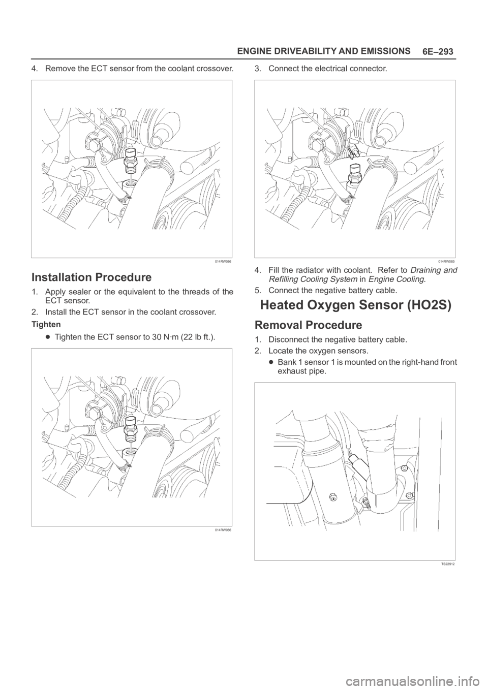
4. Remove the ECT sensor from the coolant crossover.
014RW086
Installation Procedure
1. Apply sealer or the equivalent to the threads of the
ECT sensor.
2. Install the ECT sensor in the coolant crossover.
Tighten
Tighten the ECT sensor to 30 Nꞏm (22 lb ft.).
014RW086
3. Connect the electrical connector.
014RW085
4. Fill the radiator with coolant. Refer to Draining and
Refilling Cooling System
in Engine Cooling.
5. Connect the negative battery cable.
Heated Oxygen Sensor (HO2S)
Removal Procedure
1. Disconnect the negative battery cable.
2. Locate the oxygen sensors.
Bank 1 sensor 1 is mounted on the right-hand front
exhaust pipe.
TS22912
Page 1413 of 6000
6E–296
ENGINE DRIVEABILITY AND EMISSIONS
Knock Sensor (KS)
Removal Procedure
1. Disconnect the negative battery cable.
2. Drain the cooling system. Refer to
Draining and
Filling the Cooling System
in Engine Cooling.
3. Remove the engine cover.
4. Remove the common chamber assembly.
Refer to Common Chamber in Engine Mechanical.
014RW106
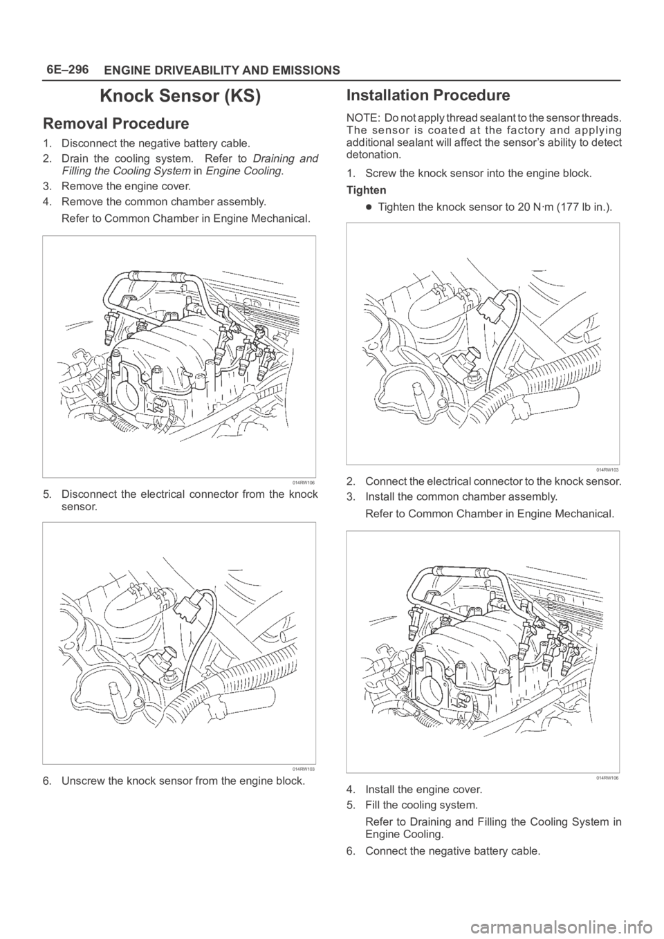
5. Disconnect the electrical connector from the knock
sensor.
014RW103
6. Unscrew the knock sensor from the engine block.
Installation Procedure
NOTE: Do not apply thread sealant to the sensor threads.
The sensor is coated at the factory and applying
additional sealant will affect the sensor’s ability to detect
detonation.
1. Screw the knock sensor into the engine block.
Tighten
Tighten the knock sensor to 20 Nꞏm (177 lb in.).
014RW103
2. Connect the electrical connector to the knock sensor.
3. Install the common chamber assembly.
Refer to Common Chamber in Engine Mechanical.
014RW106
4. Install the engine cover.
5. Fill the cooling system.
Refer to Draining and Filling the Cooling System in
Engine Cooling.
6. Connect the negative battery cable.
Page 1440 of 6000
6E–323 ENGINE DRIVEABILITY AND EMISSIONS
11. Connect the fuel filler fuse at the tank.
12. Connect the air breather hose at the tank.
TS23796
13. Fill the fuel tank with fuel.
14. Tighten the fuel filler cap.
15. Connect the negative battery cable.
Throttle Body (TB)
Removal Procedure
1. Disconnect the negative battery cable.
2. Drain the cooling system. Refer to
Cooling System.
3. Remove the accelerator cable assembly. Refer to
Accelerator Cable in Engine Speed Control System..
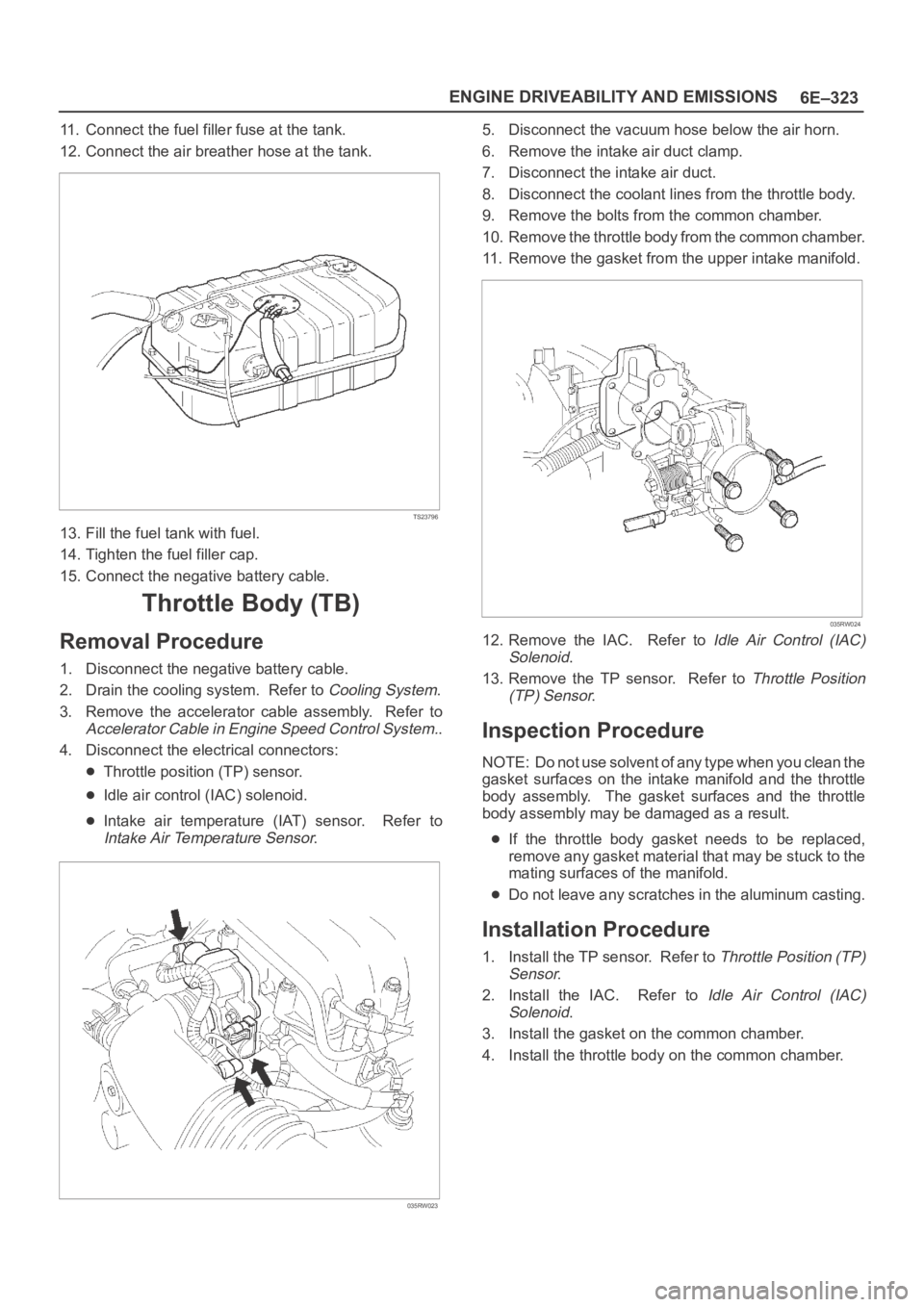
4. Disconnect the electrical connectors:
Throttle position (TP) sensor.
Idle air control (IAC) solenoid.
Intake air temperature (IAT) sensor. Refer to
Intake Air Temperature Sensor.
035RW023
5. Disconnect the vacuum hose below the air horn.
6. Remove the intake air duct clamp.
7. Disconnect the intake air duct.
8. Disconnect the coolant lines from the throttle body.
9. Remove the bolts from the common chamber.
10. Remove the throttle body from the common chamber.
11. Remove the gasket from the upper intake manifold.
035RW024
12. Remove the IAC. Refer to Idle Air Control (IAC)
Solenoid
.
13. Remove the TP sensor. Refer to
Throttle Position
(TP) Sensor
.
Inspection Procedure
NOTE: Do not use solvent of any type when you clean the
gasket surfaces on the intake manifold and the throttle
body assembly. The gasket surfaces and the throttle
body assembly may be damaged as a result.
If the throttle body gasket needs to be replaced,
remove any gasket material that may be stuck to the
mating surfaces of the manifold.
Do not leave any scratches in the aluminum casting.
Installation Procedure
1. Install the TP sensor. Refer to Throttle Position (TP)
Sensor
.
2. Install the IAC. Refer to
Idle Air Control (IAC)
Solenoid
.
3. Install the gasket on the common chamber.
4. Install the throttle body on the common chamber.
Page 1441 of 6000
6E–324
ENGINE DRIVEABILITY AND EMISSIONS
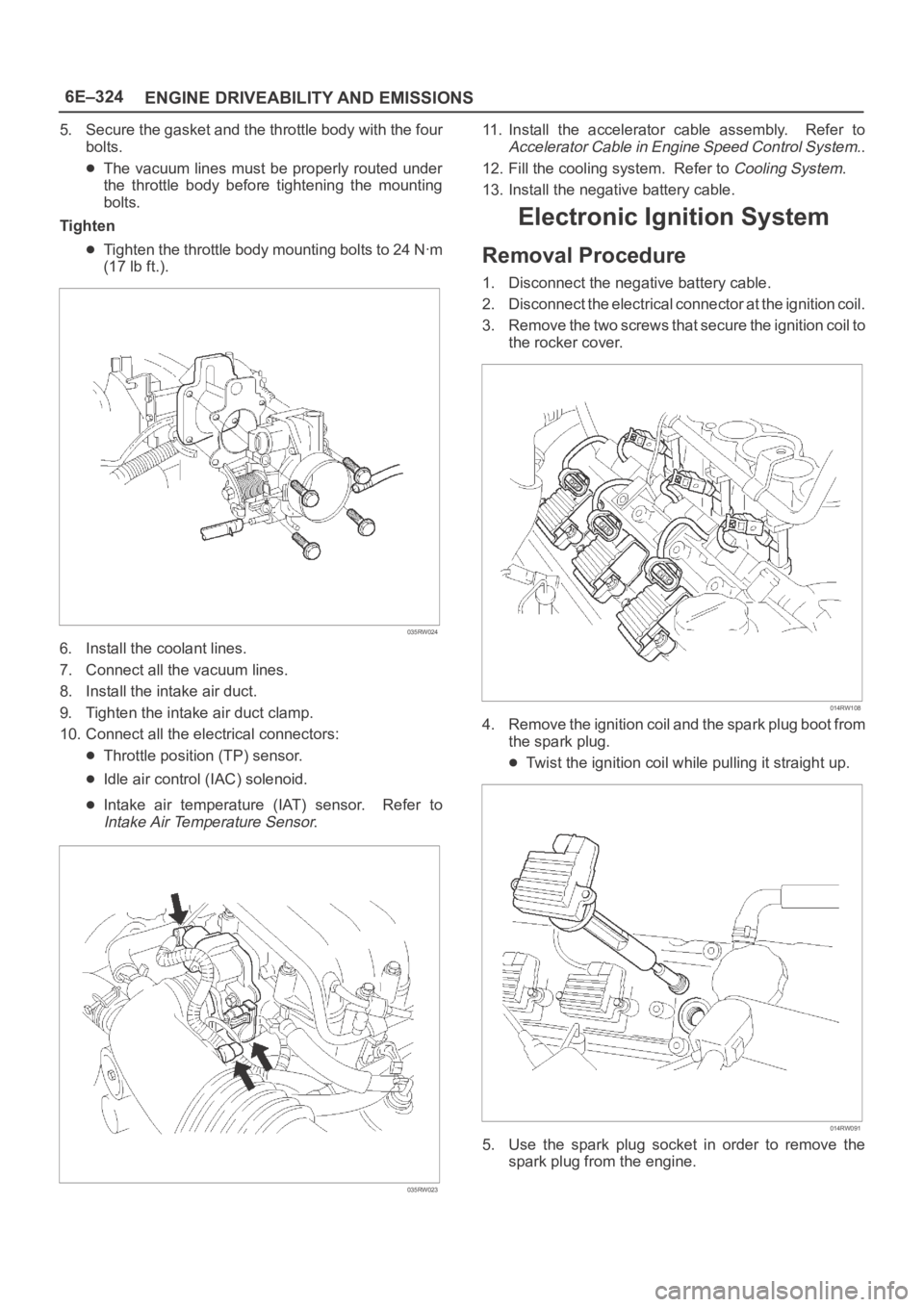
5. Secure the gasket and the throttle body with the four
bolts.
The vacuum lines must be properly routed under
the throttle body before tightening the mounting
bolts.
Tighten
Tighten the throttle body mounting bolts to 24 Nꞏm
(17 lb ft.).
035RW024
6. Install the coolant lines.
7. Connect all the vacuum lines.
8. Install the intake air duct.
9. Tighten the intake air duct clamp.
10. Connect all the electrical connectors:
Throttle position (TP) sensor.
Idle air control (IAC) solenoid.
Intake air temperature (IAT) sensor. Refer to
Intake Air Temperature Sensor.
035RW023
11. Install the accelerator cable assembly. Refer to
Accelerator Cable in Engine Speed Control System..
12. Fill the cooling system. Refer to
Cooling System.
13. Install the negative battery cable.
Electronic Ignition System
Removal Procedure
1. Disconnect the negative battery cable.
2. Disconnect the electrical connector at the ignition coil.
3. Remove the two screws that secure the ignition coil to
the rocker cover.
014RW108
4. Remove the ignition coil and the spark plug boot from
the spark plug.
Twist the ignition coil while pulling it straight up.
014RW091
5. Use the spark plug socket in order to remove the
spark plug from the engine.
Page 1455 of 6000

6E–338
ENGINE DRIVEABILITY AND EMISSIONS
RPM. A failure in the MAF sensor or circuit will set DTC
P0101, DTC P0102, or DTC P0103.
0007
Manifold Absolute Pressure (MAP) Sensor
The manifold absolute pressure (MAP) sensor responds
to changes in intake manifold pressure (vacuum). The
MAP sensor signal voltage to the PCM varies from below
2 volts at idle (high vacuum) to above 4 volts with the
ignition ON, engine not running or at wide-open throttle
(low vacuum).
The MAP sensor is used to determine the following:
Manifold pressure changes while the linear EGR flow
test diagnostic is being run. Refer to
DTC P0401.
Engine vacuum level for other diagnostics.
Barometric pressure (BARO).
If the PCM detects a voltage that is lower than the
possible range of the MAP sensor, DTC P0107 will be set.
A signal voltage higher than the possible range of the
sensor will set DTC P0108. An intermittent low or high
voltage will set DTC P1107 or DTC P1106, respectively.
The PCM can detect a shifted MAP sensor. The PCM
compares the MAP sensor signal to a calculated MAP
based on throttle position and various engine load factors.
If the PCM detects a MAP signal that varies excessively
above or below the calculated value, DTC P0106 will set.
055RW004
Powertrain Control Module (PCM)
The powertrain control module (PCM) is located in the
passenger compartment below the center console. The
PCM controls the following:
Fuel metering system.
Transmission shifting (automatic transmission only).
Ignition timing.
On-board diagnostics for powertrain functions.
The PCM constantly observes the information from
various sensors. The PCM controls the systems that
affect vehicle performance. The PCM performs the
diagnostic function of the system. It can recognize
operational problems, alert the driver through the MIL
(Service Engine Soon lamp), and store diagnostic trouble
codes (DTCs). DTCs identify the problem areas to aid the
technician in making repairs.
This engine uses 2 different control modules:
IPCM-6KT for automatic transmission-equipped
vehicles.
ISFI-6 for manual transmission-equipped vehicles.
PCM Function
The PCM supplies either 5 or 12 volts to power various
sensors or switches. The power is supplied through
resistances in the PCM which are so high in value that a
test light will not light when connected to the circuit. In
some cases, even an ordinary shop voltmeter will not give
an accurate reading because its resistance is too low.
Therefore, a digital voltmeter with at least 10 megohms
input impedance is required to ensure accurate voltage
readings. Tool J 39200 meets this requirement. The PCM
controls output circuits such as the injectors, IAC, cooling
fan relays, etc., by controlling the ground or the power
feed circuit through transistors of following device.
Output Driver Module (ODM)
Page 1465 of 6000
6E–348
ENGINE DRIVEABILITY AND EMISSIONS
oil to enter the cylinder, particularly if the deposits are
heavier on the side of the spark plug facing the intake
valve.
TS23995
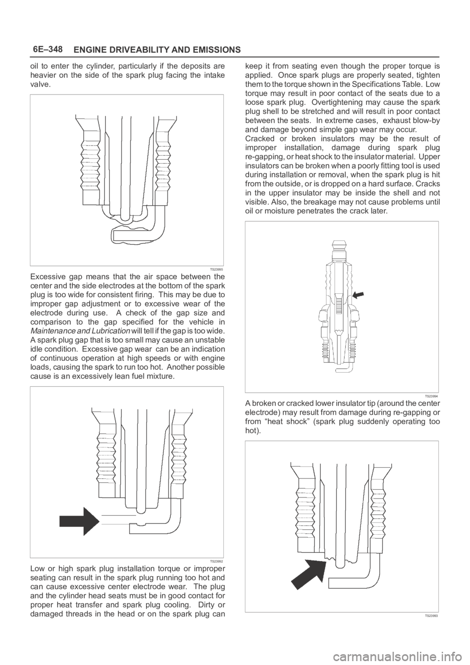
Excessive gap means that the air space between the
center and the side electrodes at the bottom of the spark
plug is too wide for consistent firing. This may be due to
improper gap adjustment or to excessive wear of the
electrode during use. A check of the gap size and
comparison to the gap specified for the vehicle in
Maintenance and Lubrication will tell if the gap is too wide.
A spark plug gap that is too small may cause an unstable
idle condition. Excessive gap wear can be an indication
of continuous operation at high speeds or with engine
loads, causing the spark to run too hot. Another possible
cause is an excessively lean fuel mixture.
TS23992
Low or high spark plug installation torque or improper
seating can result in the spark plug running too hot and
can cause excessive center electrode wear. The plug
and the cylinder head seats must be in good contact for
proper heat transfer and spark plug cooling. Dirty or
damaged threads in the head or on the spark plug cankeep it from seating even though the proper torque is
applied. Once spark plugs are properly seated, tighten
them to the torque shown in the Specifications Table. Low
torque may result in poor contact of the seats due to a
loose spark plug. Overtightening may cause the spark
plug shell to be stretched and will result in poor contact
between the seats. In extreme cases, exhaust blow-by
and damage beyond simple gap wear may occur.
Cracked or broken insulators may be the result of
improper installation, damage during spark plug
re-gapping, or heat shock to the insulator material. Upper
insulators can be broken when a poorly fitting tool is used
during installation or removal, when the spark plug is hit
from the outside, or is dropped on a hard surface. Cracks
in the upper insulator may be inside the shell and not
visible. Also, the breakage may not cause problems until
oil or moisture penetrates the crack later.
TS23994
A broken or cracked lower insulator tip (around the center
electrode) may result from damage during re-gapping or
from “heat shock” (spark plug suddenly operating too
hot).
TS23993
Page 1736 of 6000

ENGINE MECHANICAL 6A – 3
SERVICE INFORMATION
MAIN DATA AND SPECIFICATION
Engine type Diesel, four cycle water cooled inline
Camshaft type DOHC
Number of cylinders 4
Bore x stroke (mm) 95.4 x 104.9
Total piston displacement (cc) 2999
Compression ratio (to 1) 19.0
For Europe : 18.5
Engine weight (dry) N (kg/lb) 2492 (254/560) (A/T)
For Europe : 2422 (247/545) (A/T)
2649 (270/593) (M/T)
For Europe : 2697 (275/606) (M/T)
Engine idling speed (Reference) RPM 720
Compression pressure kpa (kg/cm
2/psi)-rpm 3040 (31/441)-200
Firing order 1–3–4–2
VALVE SYSTEM
Intake valves open at: B.T.D.C. 3°
close at: A.B.D.C. 57.6°
Exhaust valves open at: B.B.D.C. 56.5°
close at: A.T.D.C. 5°
Valve clearance (at cold) mm (in)
intake: 0.15 (0.006)
exhaust: 0.25 (0.01)
Oil filter Full flow and bypass combined type
Oil capacity (Original factory fill or rebuilt engine) 9.0 liters (7.9 US quarts)
Oil capacity (Service change)
with filter change 6.0 liters (6.3 US quarts)
without filter change 5.0 liters (5.3 US quarts)
Oil cooler Water cooled type
Inter cooler Air cooled type
Turbocharger method
Control method Wastegate control
Lubrication Pressurized control
Cooling method Coolant cooled
Crankshaft
As tufftriding (Nitrizing treatment) is applied to increase
crankshaft strength, crankpins and journals should not
be reground.
Piston Cooling
An oiling jet device for piston cooling is provided in the
lubricating oil circuit from the cylinder block oil gallery
via a check valve.
Take care not to damage any oiling jet when removing
and installing piston and connecting assembly.
Fuel Injection System
The injection system is oil rail type.
Quick On Start 4 System
QOS4 preheating system which features a quick-on
glow plug with thermometer control of the glowing time
and the afterglow time function, is applied.
Page 1737 of 6000

6A – 4 ENGINE MECHANICAL
Engine Cooling
Starting System
Cooling system Coolant forced circulation
Radiator (2 tube in row) Tube type corrugated
Heat radiation capacity J/h (kcal/h) 318 x 10
6(76000)
Heat radiation area m
2(ft2) 15.63 (1.454)
Front area m
2(ft2) 0.309 (2.029)
Dry weight N (kg/lb) 83 (8.5/18.7)
Radiator cap
Valve opening pressure kPa (kg/cm
2/ psi) 93.3 – 122.7 (0.95 – 1.25/13.5 – 17.8)
Coolant capacity lit (Imp.qt./US qt.) M/T 2.5 (2.2/2.6) A/T 2.4 (2.1/2.5)
Coolant pump Centrifugal impeller type
Pulley ratio (to 1) 1.2
Coolant total capacity lit (Imp.qt./US qt.) 9.3 (8.2/9.8)
Model HITACHI S14-0
Rating
Vo l t a ge V 1 2
Output kW 2.8
Time sec 30
Number of teeth of pinion 9
Rotating direction (as viewed from pinion) Clockwise
Weight (approx.) N(kg/lb) 49 (5.0/11)
No-load characteristics
Voltage/current V/A 11/160 or less
Speed rpm 4000 or more
Load characteristics
Voltage/current V/A 8.76/300
Torque Nꞏm(kgꞏm/lbꞏft) 7.4 (0.75/5.4) or more
Speed rpm 1700 or more
Locking characteristics
Voltage/current V/A 2.5/1100 or less
Torque Nꞏm(kgꞏm/lbꞏft) 18.6 (1.9/14) or more