1998 OPEL FRONTERA cooling
[x] Cancel search: coolingPage 1143 of 6000
6E–26
ENGINE DRIVEABILITY AND EMISSIONS
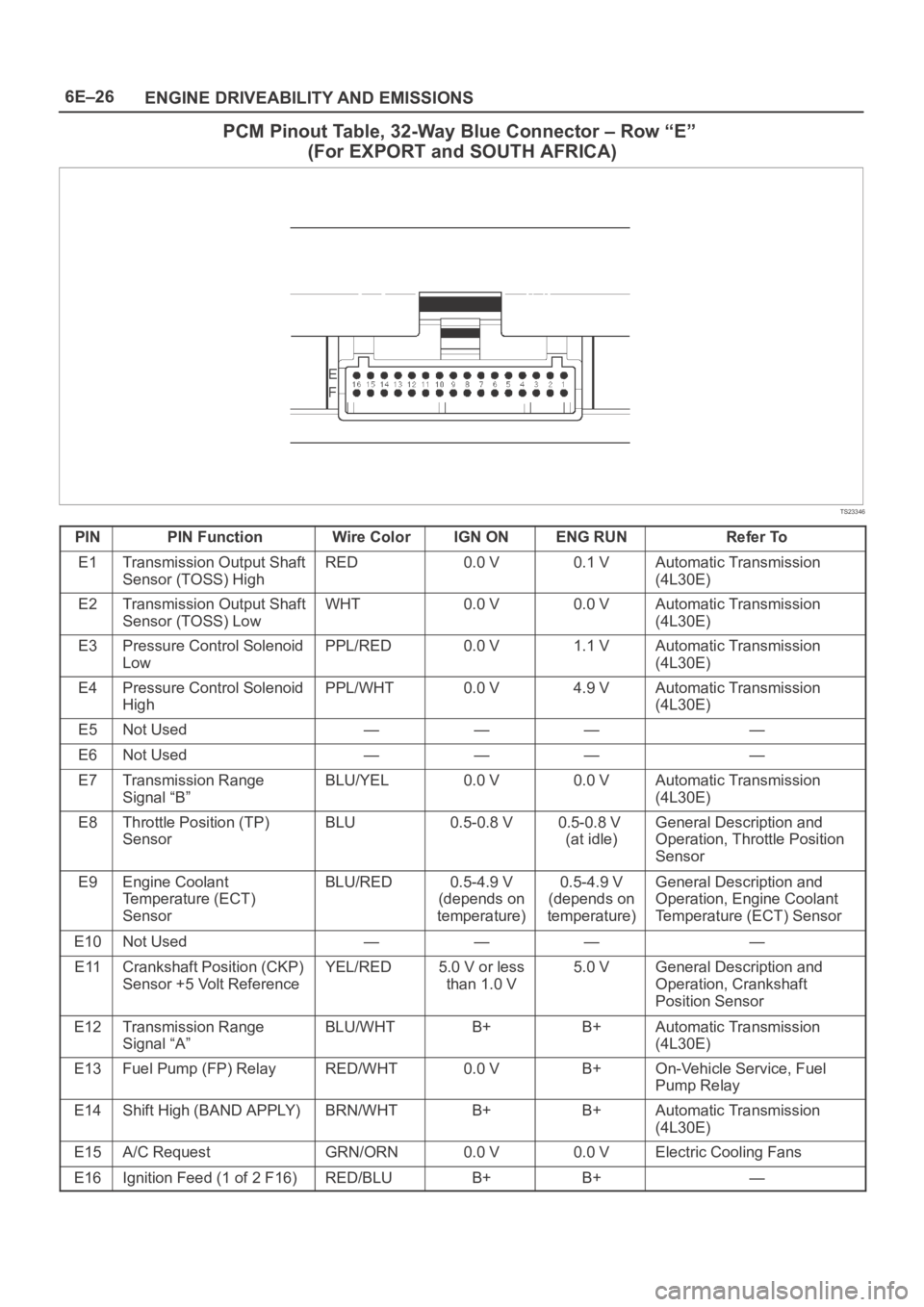
PCM Pinout Table, 32-Way Blue Connector – Row “E”
(For EXPORT and SOUTH AFRICA)
TS23346
PINPIN FunctionWire ColorIGN ONENG RUNRefer To
E1Transmission Output Shaft
Sensor (TOSS) HighRED0.0 V0.1 VAutomatic Transmission
(4L30E)
E2Transmission Output Shaft
Sensor (TOSS) LowWHT0.0 V0.0 VAutomatic Transmission
(4L30E)
E3Pressure Control Solenoid
LowPPL/RED0.0 V1.1 VAutomatic Transmission
(4L30E)
E4Pressure Control Solenoid
HighPPL/WHT0.0 V4.9 VAutomatic Transmission
(4L30E)
E5Not Used————
E6Not Used————
E7Transmission Range
Signal “B”BLU/YEL0.0 V0.0 VAutomatic Transmission
(4L30E)
E8Throttle Position (TP)
SensorBLU0.5-0.8 V0.5-0.8 V
(at idle)General Description and
Operation, Throttle Position
Sensor
E9Engine Coolant
Temperature (ECT)
SensorBLU/RED0.5-4.9 V
(depends on
temperature)0.5-4.9 V
(depends on
temperature)General Description and
Operation, Engine Coolant
Temperature (ECT) Sensor
E10Not Used————
E11Crankshaft Position (CKP)
Sensor +5 Volt ReferenceYEL/RED5.0 V or less
than 1.0 V5.0 VGeneral Description and
Operation, Crankshaft
Position Sensor
E12Transmission Range
Signal “A”BLU/WHTB+B+Automatic Transmission
(4L30E)
E13Fuel Pump (FP) RelayRED/WHT0.0 VB+On-Vehicle Service, Fuel
Pump Relay
E14Shift High (BAND APPLY)BRN/WHTB+B+Automatic Transmission
(4L30E)
E15A/C RequestGRN/ORN0.0 V0.0 VElectric Cooling Fans
E16Ignition Feed (1 of 2 F16)RED/BLUB+B+—
Page 1156 of 6000
6E–39 ENGINE DRIVEABILITY AND EMISSIONS
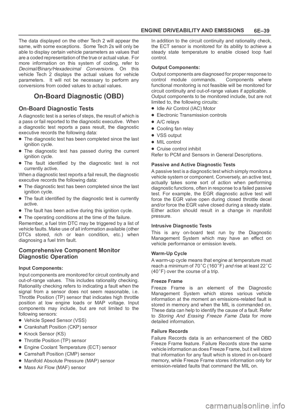
The data displayed on the other Tech 2 will appear the
same, with some exceptions. Some Tech 2s will only be
able to display certain vehicle parameters as values that
are a coded representation of the true or actual value. For
more information on this system of coding, refer to
Decimal/Binary/Hexadecimal Conversions. On this
vehicle Tech 2 displays the actual values for vehicle
parameters. It will not be necessary to perform any
conversions from coded values to actual values.
On-Board Diagnostic (OBD)
On-Board Diagnostic Tests
A diagnostic test is a series of steps, the result of which is
a pass or fail reported to the diagnostic executive. When
a diagnostic test reports a pass result, the diagnostic
executive records the following data:
The diagnostic test has been completed since the last
ignition cycle.
The diagnostic test has passed during the current
ignition cycle.
The fault identified by the diagnostic test is not
currently active.
W h e n a d i a g n o s t i c t e s t r e p o r t s a fail result, the diagnostic
executive records the following data:
The diagnostic test has been completed since the last
ignition cycle.
The fault identified by the diagnostic test is currently
active.
The fault has been active during this ignition cycle.
The operating conditions at the time of the failure.
Remember, a fuel trim DTC may be triggered by a list of
vehicle faults. Make use of all information available (other
DTCs stored, rich or lean condition, etc.) when
diagnosing a fuel trim fault.
Comprehensive Component Monitor
Diagnostic Operation
Input Components:
Input components are monitored for circuit continuity and
out-of-range values. This includes rationality checking.
Rationality checking refers to indicating a fault when the
signal from a sensor does not seem reasonable, i.e.
Throttle Position (TP) sensor that indicates high throttle
position at low engine loads or MAP voltage. Input
components may include, but are not limited to the
following sensors:
Vehicle Speed Sensor (VSS)
Crankshaft Position (CKP) sensor
Knock Sensor (KS)
Throttle Position (TP) sensor
Engine Coolant Temperature (ECT) sensor
Camshaft Position (CMP) sensor
Manifold Absolute Pressure (MAP) sensor
Mass Air Flow (MAF) sensorIn addition to the circuit continuity and rationality check,
the ECT sensor is monitored for its ability to achieve a
steady state temperature to enable closed loop fuel
control.
Output Components:
Output components are diagnosed for proper response to
control module commands. Components where
functional monitoring is not feasible will be monitored for
circuit continuity and out-of-range values if applicable.
Output components to be monitored include, but are not
limited to, the following circuits:
Idle Air Control (IAC) Motor
Electronic Transmission controls
A/C relays
Cooling fan relay
VSS output
MIL control
Cruise control inhibit
Refer to PCM and Sensors in General Descriptions.
Passive and Active Diagnostic Tests
A passive test is a diagnostic test which simply monitors a
vehicle system or component. Conversely, an active test,
actually takes some sort of action when performing
diagnostic functions, often in response to a failed passive
test. For example, the EGR diagnostic active test will
force the EGR valve open during closed throttle decel
and/or force the EGR valve closed during a steady state.
Either action should result in a change in manifold
pressure.
Intrusive Diagnostic Tests
This is any on-board test run by the Diagnostic
Management System which may have an effect on
vehicle performance or emission levels.
Warm-Up Cycle
A warm-up cycle means that engine at temperature must
reach a minimum of 70
C (160F) and rise at least 22C
(40
F) over the course of a trip.
Freeze Frame
Freeze Frame is an element of the Diagnostic
Management System which stores various vehicle
information at the moment an emissions-related fault is
stored in memory and when the MIL is commanded on.
These data can help to identify the cause of a fault. Refer
to
Storing And Erasing Freeze Fame Data for more
detailed information.
Failure Records
Failure Records data is an enhancement of the OBD
Freeze Frame feature. Failure Records store the same
vehicle information as does Freeze Frame, but it will store
that information for any fault which is stored in on-board
memory, while Freeze Frame stores information only for
emission-related faults that command the MIL on.
Page 1387 of 6000
6E–270
ENGINE DRIVEABILITY AND EMISSIONS
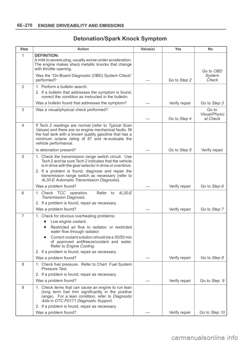
Detonation/Spark Knock Symptom
StepActionVa l u e ( s )Ye sNo
1DEFINITION:
A mild to severe ping, usually worse under acceleration.
The engine makes sharp metallic knocks that change
with throttle opening.
Was the “On-Board Diagnostic (OBD) System Check”
performed?
—Go to Step 2
Go to OBD
System
Check
21. Perform a bulletin search.
2. If a bulletin that addresses the symptom is found,
correct the condition as instructed in the bulletin.
Was a bulletin found that addresses the symptom?
—Verify repairGo to Step 3
3Was a visual/physical check performed?
—Go to Step 4
Go to
Visual/Physic
al Check
4If Tech 2 readings are normal (refer to Ty p i c a l S c a n
Va lu es
) and there are no engine mechanical faults, fill
the fuel tank with a known quality gasoline that has a
minimum octane rating of 87 and re-evaluate the
vehicle performance.
Is detonation present?
—Go to Step 5Verify repair
51. Check the transmission range switch circuit. Use
Tech 2 and be sure Tech 2 indicates that the vehicle
is in drive with the gear selector in drive or overdrive.
2. If a problem is found, diagnose and repair the
transmission range switch as necessary (refer to
4L30-E Automatic Transmission Diagnosis).
Was a problem found?
—Verify repairGo to Step 6
61. Check TCC operation. Refer to 4L30-E
Transmission Diagnosis
.
2. If a problem is found, repair as necessary.
Was a problem found?
—Verify repairGo to Step 7
71. Check for obvious overheating problems:
Low engine coolant.
Restricted air flow to radiator, or restricted
water flow through radiator.
Correct coolant solution should be a 50/50 mix
of approved antifreeze/coolant and water.
Refer to
Engine Cooling.
2. If a problem is found, repair as necessary.
Was a problem found?
—Verify repairGo to Step 8
81. Check fuel pressure. Refer to Chart Fuel System
Pressure Test.
2. If a problem is found, repair as necessary.
Was a problem found?
—Verify repairGo to Step 9
91. Check items that can cause an engine to run lean
(long term fuel trim significantly in the positive
range). For a lean condition, refer to
Diagnostic
Aids
in DTC P0171 Diagnostic Support.
2. If a problem is found, repair as necessary.
Was a problem found?
—Verify repairGo to Step 10
Page 1392 of 6000
6E–275 ENGINE DRIVEABILITY AND EMISSIONS
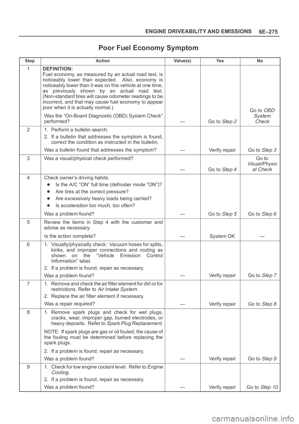
Poor Fuel Economy Symptom
StepActionVa l u e ( s )Ye sNo
1DEFINITION:
Fuel economy, as measured by an actual road test, is
noticeably lower than expected. Also, economy is
noticeably lower than it was on this vehicle at one time,
as previously shown by an actual road test.
(Non-standard tires will cause odometer readings to be
incorrect, and that may cause fuel economy to appear
poor when it is actually normal.)
Was the “On-Board Diagnostic (OBD) System Check”
performed?
—Go to Step 2
Go to OBD
System
Check
21. Perform a bulletin search.
2. If a bulletin that addresses the symptom is found,
correct the condition as instructed in the bulletin.
Was a bulletin found that addresses the symptom?
—Verify repairGo to Step 3
3Was a visual/physical check performed?
—Go to Step 4
Go to
Visual/Physic
al Check
4Check owner’s driving habits.
Is the A/C “ON” full time (defroster mode “ON”)?
Are tires at the correct pressure?
Are excessively heavy loads being carried?
Is acceleration too much, too often?
Was a problem found?
—Go to Step 5Go to Step 6
5Review the items in Step 4 with the customer and
advise as necessary.
Is the action complete?
—System OK—
61. Visually/physically check: Vacuum hoses for splits,
kinks, and improper connections and routing as
shown on the “Vehicle Emission Control
Information” label.
2. If a problem is found, repair as necessary.
Was a problem found?
—Verify repairGo to Step 7
71. Remove and check the air filter element for dirt or for
restrictions. Refer to
Air Intake System.
2. Replace the air filter element if necessary.
Was a repair required?
—Verify repairGo to Step 8
81. Remove spark plugs and check for wet plugs,
cracks, wear, improper gap, burned electrodes, or
heavy deposits. Refer to
Spark Plug Replacement.
NOTE: If spark plugs are gas or oil fouled, the cause of
the fouling must be determined before replacing the
spark plugs.
2. If a problem is found, repair as necessary.
Was a problem found?
—Verify repairGo to Step 9
91. Check for low engine coolant level. Refer to Engine
Cooling
.
2. If a problem is found, repair as necessary.
Was a problem found?
—Verify repairGo to Step 10
Page 1393 of 6000
6E–276
ENGINE DRIVEABILITY AND EMISSIONS
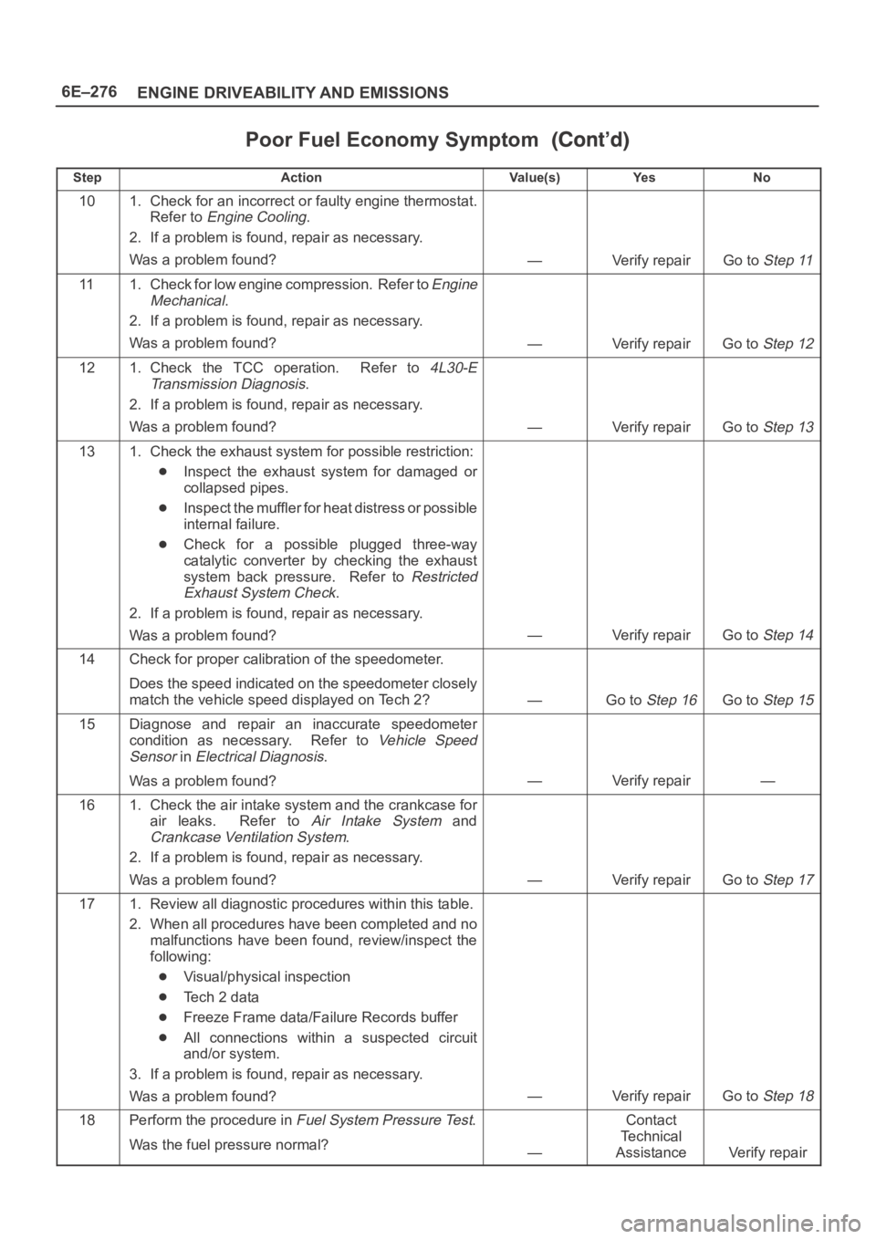
Poor Fuel Economy Symptom
StepNo Ye s Va l u e ( s ) Action
101. Check for an incorrect or faulty engine thermostat.
Refer to
Engine Cooling.
2. If a problem is found, repair as necessary.
Was a problem found?
—Verify repairGo to Step 11
111. Check for low engine compression. Refer to Engine
Mechanical
.
2. If a problem is found, repair as necessary.
Was a problem found?
—Verify repairGo to Step 12
121. Check the TCC operation. Refer to 4L30-E
Transmission Diagnosis
.
2. If a problem is found, repair as necessary.
Was a problem found?
—Verify repairGo to Step 13
131. Check the exhaust system for possible restriction:
Inspect the exhaust system for damaged or
collapsed pipes.
Inspect the muffler for heat distress or possible
internal failure.
Check for a possible plugged three-way
catalytic converter by checking the exhaust
system back pressure. Refer to
Restricted
Exhaust System Check
.
2. If a problem is found, repair as necessary.
Was a problem found?
—Verify repairGo to Step 14
14Check for proper calibration of the speedometer.
Does the speed indicated on the speedometer closely
match the vehicle speed displayed on Tech 2?
—Go to Step 16Go to Step 15
15Diagnose and repair an inaccurate speedometer
condition as necessary. Refer to
Vehicle Speed
Sensor
in Electrical Diagnosis.
Was a problem found?
—Verify repair—
161. Check the air intake system and the crankcase for
air leaks. Refer to
Air Intake System and
Crankcase Ventilation System.
2. If a problem is found, repair as necessary.
Was a problem found?
—Verify repairGo to Step 17
171. Review all diagnostic procedures within this table.
2. When all procedures have been completed and no
malfunctions have been found, review/inspect the
following:
Visual/physical inspection
Te c h 2 d a t a
Freeze Frame data/Failure Records buffer
All connections within a suspected circuit
and/or system.
3. If a problem is found, repair as necessary.
Was a problem found?
—Verify repairGo to Step 18
18Perform the procedure in Fuel System Pressure Test.
Was the fuel pressure normal?
—
Contact
Te c h n i c a l
Assistance
Verify repair
Page 1394 of 6000
6E–277 ENGINE DRIVEABILITY AND EMISSIONS
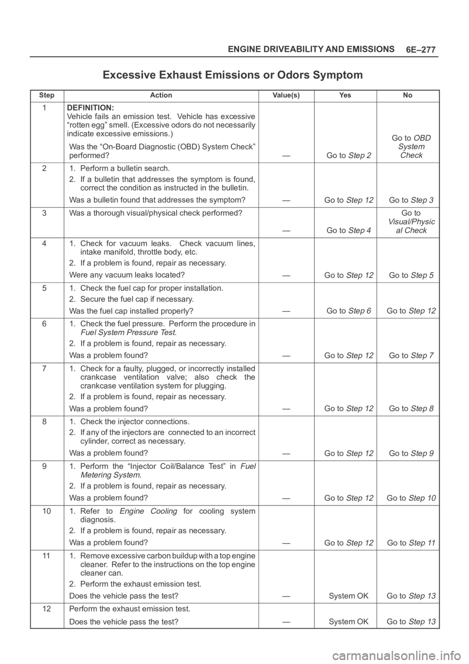
Excessive Exhaust Emissions or Odors Symptom
StepActionVa l u e ( s )Ye sNo
1DEFINITION:
Vehicle fails an emission test. Vehicle has excessive
“rotten egg” smell. (Excessive odors do not necessarily
indicate excessive emissions.)
Was the “On-Board Diagnostic (OBD) System Check”
performed?
—Go to Step 2
Go to OBD
System
Check
21. Perform a bulletin search.
2. If a bulletin that addresses the symptom is found,
correct the condition as instructed in the bulletin.
Was a bulletin found that addresses the symptom?
—Go to Step 12Go to Step 3
3Was a thorough visual/physical check performed?
—Go to Step 4
Go to
Visual/Physic
al Check
41. Check for vacuum leaks. Check vacuum lines,
intake manifold, throttle body, etc.
2. If a problem is found, repair as necessary.
Were any vacuum leaks located?
—Go to Step 12Go to Step 5
51. Check the fuel cap for proper installation.
2. Secure the fuel cap if necessary.
Was the fuel cap installed properly?
—Go to Step 6Go to Step 12
61. Check the fuel pressure. Perform the procedure in
Fuel System Pressure Test.
2. If a problem is found, repair as necessary.
Was a problem found?
—Go to Step 12Go to Step 7
71. Check for a faulty, plugged, or incorrectly installed
crankcase ventilation valve; also check the
crankcase ventilation system for plugging.
2. If a problem is found, repair as necessary.
Was a problem found?
—Go to Step 12Go to Step 8
81. Check the injector connections.
2. If any of the injectors are connected to an incorrect
cylinder, correct as necessary.
Was a problem found?
—Go to Step 12Go to Step 9
91. Perform the “Injector Coil/Balance Test” in Fuel
Metering System
.
2. If a problem is found, repair as necessary.
Was a problem found?
—Go to Step 12Go to Step 10
101. Refer to Engine Cooling for cooling system
diagnosis.
2. If a problem is found, repair as necessary.
Was a problem found?
—Go to Step 12Go to Step 11
111. Remove excessive carbon buildup with a top engine
cleaner. Refer to the instructions on the top engine
cleaner can.
2. Perform the exhaust emission test.
Does the vehicle pass the test?
—System OKGo to Step 13
12Perform the exhaust emission test.
Does the vehicle pass the test?
—System OKGo to Step 13
Page 1406 of 6000
6E–289 ENGINE DRIVEABILITY AND EMISSIONS
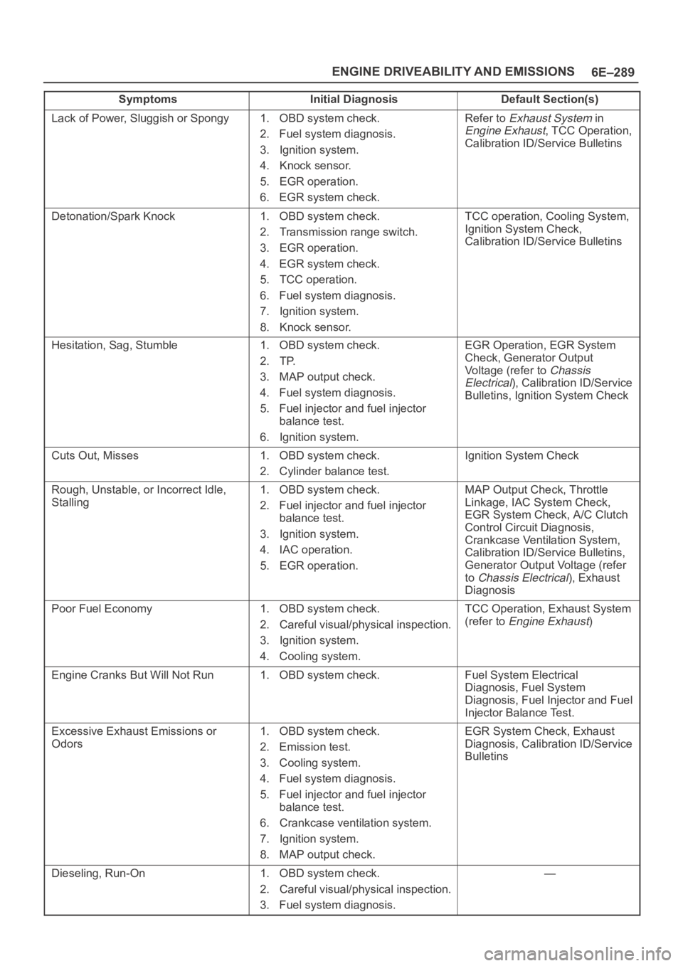
Symptoms Default Section(s)Initial Diagnosis
Lack of Power, Sluggish or Spongy1. OBD system check.
2. Fuel system diagnosis.
3. Ignition system.
4. Knock sensor.
5. EGR operation.
6. EGR system check.Refer to Exhaust System in
Engine Exhaust, TCC Operation,
Calibration ID/Service Bulletins
Detonation/Spark Knock1. OBD system check.
2. Transmission range switch.
3. EGR operation.
4. EGR system check.
5. TCC operation.
6. Fuel system diagnosis.
7. Ignition system.
8. Knock sensor.TCC operation, Cooling System,
Ignition System Check,
Calibration ID/Service Bulletins
Hesitation, Sag, Stumble1. OBD system check.
2. TP.
3. MAP output check.
4. Fuel system diagnosis.
5. Fuel injector and fuel injector
balance test.
6. Ignition system.EGR Operation, EGR System
Check, Generator Output
Voltage (refer to
Chassis
Electrical
), Calibration ID/Service
Bulletins, Ignition System Check
Cuts Out, Misses1. OBD system check.
2. Cylinder balance test.Ignition System Check
Rough, Unstable, or Incorrect Idle,
Stalling1. OBD system check.
2. Fuel injector and fuel injector
balance test.
3. Ignition system.
4. IAC operation.
5. EGR operation.MAP Output Check, Throttle
Linkage, IAC System Check,
EGR System Check, A/C Clutch
Control Circuit Diagnosis,
Crankcase Ventilation System,
Calibration ID/Service Bulletins,
Generator Output Voltage (refer
to
Chassis Electrical), Exhaust
Diagnosis
Poor Fuel Economy1. OBD system check.
2. Careful visual/physical inspection.
3. Ignition system.
4. Cooling system.TCC Operation, Exhaust System
(refer to
Engine Exhaust)
Engine Cranks But Will Not Run1. OBD system check.Fuel System Electrical
Diagnosis, Fuel System
Diagnosis, Fuel Injector and Fuel
Injector Balance Test.
Excessive Exhaust Emissions or
Odors1. OBD system check.
2. Emission test.
3. Cooling system.
4. Fuel system diagnosis.
5. Fuel injector and fuel injector
balance test.
6. Crankcase ventilation system.
7. Ignition system.
8. MAP output check.EGR System Check, Exhaust
Diagnosis, Calibration ID/Service
Bulletins
Dieseling, Run-On1. OBD system check.
2. Careful visual/physical inspection.
3. Fuel system diagnosis.—
Page 1409 of 6000
6E–292
ENGINE DRIVEABILITY AND EMISSIONS
Crankshaft Position (CKP)
Sensor
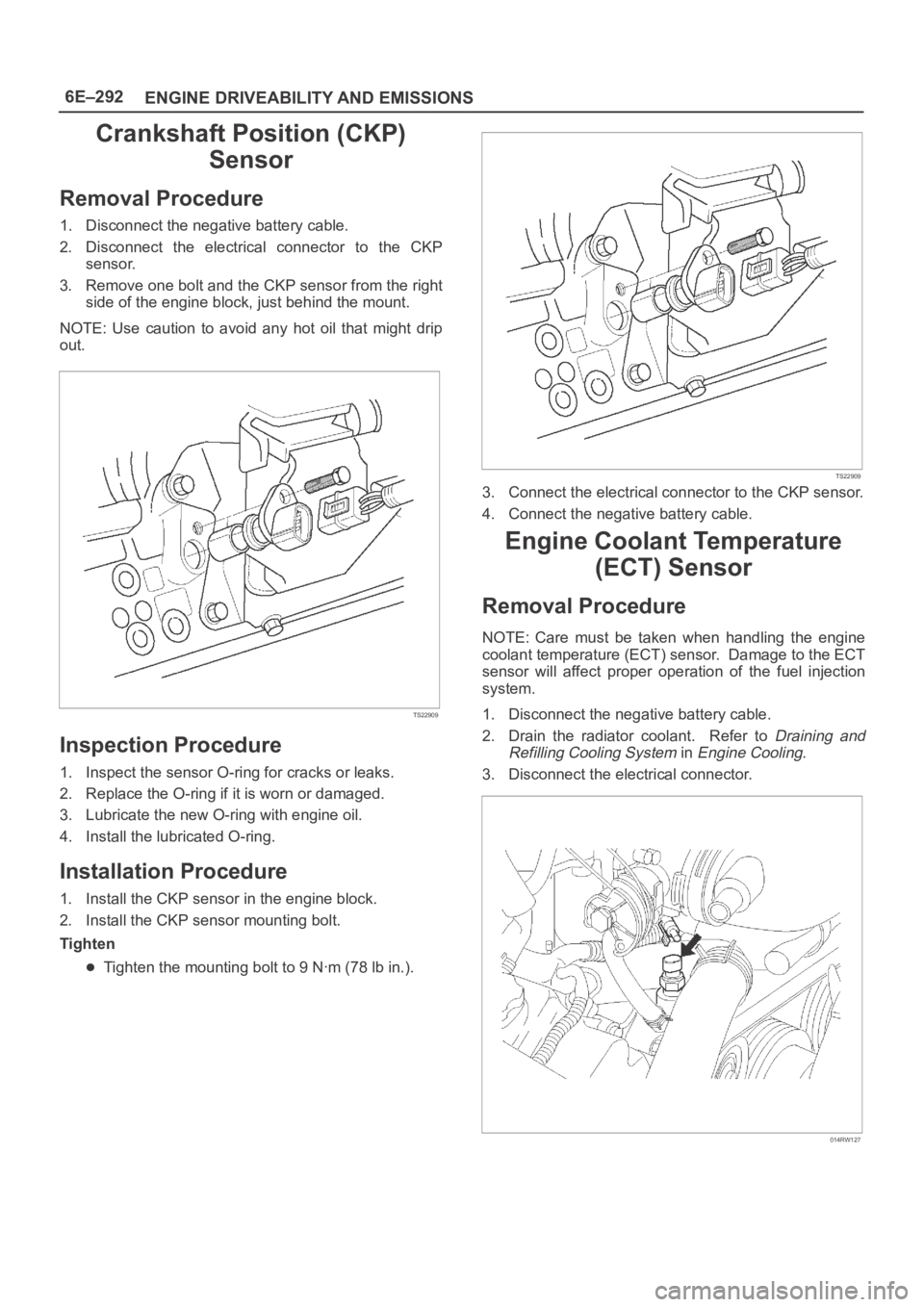
Removal Procedure
1. Disconnect the negative battery cable.
2. Disconnect the electrical connector to the CKP
sensor.
3. Remove one bolt and the CKP sensor from the right
side of the engine block, just behind the mount.
NOTE: Use caution to avoid any hot oil that might drip
out.
TS22909
Inspection Procedure
1. Inspect the sensor O-ring for cracks or leaks.
2. Replace the O-ring if it is worn or damaged.
3. Lubricate the new O-ring with engine oil.
4. Install the lubricated O-ring.
Installation Procedure
1. Install the CKP sensor in the engine block.
2. Install the CKP sensor mounting bolt.
Tighten
Tighten the mounting bolt to 9 Nꞏm (78 lb in.).
TS22909
3. Connect the electrical connector to the CKP sensor.
4. Connect the negative battery cable.
Engine Coolant Temperature
(ECT) Sensor
Removal Procedure
NOTE: Care must be taken when handling the engine
coolant temperature (ECT) sensor. Damage to the ECT
sensor will affect proper operation of the fuel injection
system.
1. Disconnect the negative battery cable.
2. Drain the radiator coolant. Refer to
Draining and
Refilling Cooling System
in Engine Cooling.
3. Disconnect the electrical connector.
014RW127