Page 5846 of 6000

AUTOMATIC TRANSMISSION (AW30-40LE) 7A–65
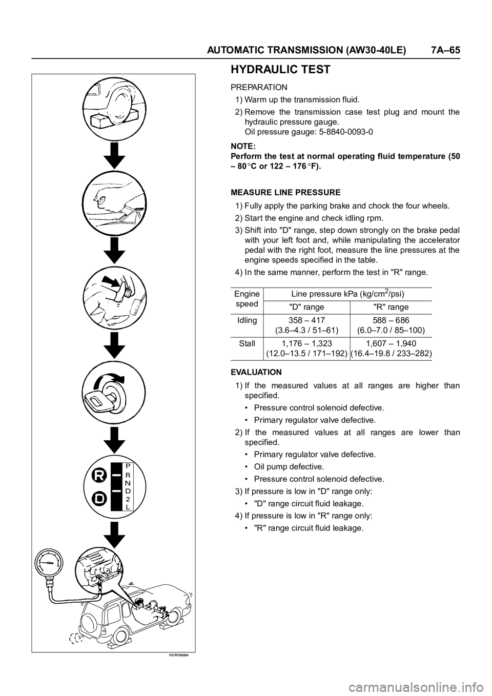
F07RY00004
HYDRAULIC TEST
PREPARATION
1) Warm up the transmission fluid.
2) Remove the transmission case test plug and mount the
hydraulic pressure gauge.
Oil pressure gauge: 5-8840-0093-0
NOTE:
Perform the test at normal operating fluid temperature (50
– 80
C or 122 – 176F).
MEASURE LINE PRESSURE
1) Fully apply the parking brake and chock the four wheels.
2) Start the engine and check idling rpm.
3) Shift into "D" range, step down strongly on the brake pedal
with your left foot and, while manipulating the accelerator
pedal with the right foot, measure the line pressures at the
engine speeds specified in the table.
4) In the same manner, perform the test in "R" range.
EVALUATION
1) If the measured values at all ranges are higher than
specified.
• Pressure control solenoid defective.
• Primary regulator valve defective.
2) If the measured values at all ranges are lower than
specified.
• Primary regulator valve defective.
• Oil pump defective.
• Pressure control solenoid defective.
3) If pressure is low in "D" range only:
• "D" range circuit fluid leakage.
4) If pressure is low in "R" range only:
• "R" range circuit fluid leakage. Engine
speedLine pressure kPa (kg/cm
2/psi)
"D" range "R" range
Idling 358 – 417
(3.6–4.3 / 51–61)588 – 686
(6.0–7.0 / 85–100)
Stall 1,176 – 1,323
(12.0–13.5 / 171–192)1,607 – 1,940
(16.4–19.8 / 233–282)
Page 5853 of 6000

7A–72 AUTOMATIC TRANSMISSION (AW30-40LE)
TCM STANDARD VOLTAGE
Check circuitTe r m i n a l
Measuring condition Voltage (V)
+-
Throttle position sensorC79-6 C79-28Throttle fully opened (WOT) 3.47
4.56
Throttle fully closed (idling) 0.25
0.45
C79-19 C79-18 Key switch ON 4.75
5.25
Output revolution sensor C79-4 C79-16 Engine idling in gear 0
3
Input revolution sensor C79-5 C79-17 Engine idling 0
3
Speed meter sensor C79-7C78-15
or -19Vehicle speed 10
20 km/h Less than 1.4
about 5
Brake switch C78-18C78-15
or -19Depress brake 7
16
Release brake Less than 1
O/D OFF switch C79-3C78-15
or -19O/D OFF switch ON (O/D OFF) 7
16
O/D OFF switch OFF (O/D ON) Less than 1
Neutral start switch
C79-2C78-15
or -19Selector “P” range 7
16
(P) Selector all ranges except “P” Less than 1
Neutral start switch
C79-1C78-15
or -19Selector “R” range 7
16
(R) Selector all ranges except “R” Less than 1
Neutral start switch
C79-9C78-15
or -19Selector “N” range 7
16
(N) Selector all ranges except “N” Less than 1
Neutral start switch
C79-8C78-15
or -19Selector “D” range 7
16
(D) Selector all ranges except “D” Less than 1
Neutral start switch
C79-21C78-15
or -19Selector “2” range 7
16
(2) Selector all ranges except “2” Less than 1
Neutral start switch
C79-20C78-15
or -19Selector “L” range 7
16
(L) Selector all ranges except “L” Less than 1
Engine revolution signal C79-15C78-15
or -19Engine idling Less than 1.4
9 16
Diagnosis terminal C79-24C78-15
or -19Self-diagnosis ON
0
1.5
Power pattern switch C79-23C78-15
or -19Power pattern switch OFF (NORMAL) 8
16
Power pattern switch ON (POWER) Less than 1.4
Winter select switch C79-13C78-15
or -19Switch OFF 8
16
Switch ON Less than 1.4
Electrical source (Battery) C78-13C78-15
or -19—
9
16
Electrical source (Ignition) C78-20C78-15
or -19Key switch ON
9
16
Oil temperature warning lamp C79-11C78-15
or -19Oil temperature warning lamp ON Less than 1
Oil temperature warning lamp OFF 8
16
“CHECK TRANS lamp” C79-10C78-15
or -19“CHECK TRANS” lamp ON Less than 1
“CHECK TRANS” lamp OFF 8
16
Power lamp C79-22C78-15
or -19Power lamp ON Less than 1
Powe r l a m p O F F 8
16
Page 5854 of 6000
AUTOMATIC TRANSMISSION (AW30-40LE) 7A–73
Check circuitTe r m i n a l
Measuring condition Voltage (V)
+-
Winter lamp C79-12C78-15
or -19Winter lamp ON Less than 1
Winter lamp OFF 8
16
Solenoid S1 C78-4C78-15
or -19OFF (3rd or O/D) Less than 1
ON (1st or 2nd) 8
16
Solenoid S2 C78-3C78-15
or -19OFF (1st or O/D) Less than 1
ON (2nd or 3rd) 8
16
Lock up solenoid SL C78-12C78-15
or -19OFF (Lock up OFF) Less than 1
ON (Lock up ON) 8
16
Pressure control solenoid C78-11 C78-8At throttle pressure changing Less than
1
8-16
Oil temperature sensor C79-18 C79-27ATF temperature 20
C4.70
ATF temperature 80
C3.65
Tech 2 diagnosis terminal
(J1850)C78-6C78-15
or -19On diagnosis communication 0-1.5
6.25-8.0
Throttle position sensor
(ground)C79-19C78-15
or -19Key switch ON
-0.1
0.1
Page 5856 of 6000

AUTOMATIC TRANSMISSION (AW30-40LE) 7A–75
ON-VEHICLE SERVICE
242RX00001
TRANSIMISSION FLUID LEVEL AND
CONDITION
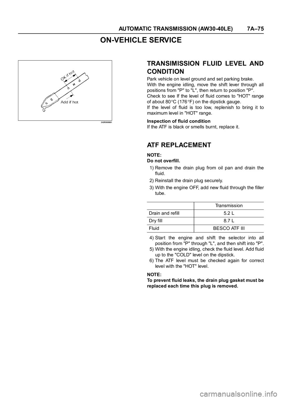
Park vehicle on level ground and set parking brake.
With the engine idling, move the shift lever through all
positions from "P" to "L", then return to position "P".
Check to see If the level of fluid comes to "HOT" range
of about 80
C (176F) on the dipstick gauge.
If the level of fluid is too low, replenish to bring it to
maximum level in "HOT" range.
Inspection of fluid condition
If the ATF is black or smells burnt, replace it.
ATF REPLACEMENT
NOTE:
Do not overfill.
1) Remove the drain plug from oil pan and drain the
fluid.
2) Reinstall the drain plug securely.
3) With the engine OFF, add new fluid through the filler
tube.
4) Star t the engine and shift the selector into all
position from "P" through "L", and then shift into "P".
5) With the engine idling, check the fluid level. Add fluid
up to the "COLD" level on the dipstick.
6) The ATF level must be checked again for correct
level with the "HOT" level.
NOTE:
To prevent fluid leaks, the drain plug gasket must be
replaced each time this plug is removed.
Tr a n s m i s s i o n
Drain and refill 5.2 L
Dry fill 8.7 L
Fluid BESCO ATF III
Page 5859 of 6000
7A–78 AUTOMATIC TRANSMISSION (AW30-40LE)
F07RY00019
225RY00001
220RY00001
244RX00001
PATTERN SELECT SWITCH INSPECTION
Inspect that there is continuity between each terminals.
OVERDRIVE OFF SWITCH INSPECTION
Inspect that there is continuity between terminals 2 and 4.
SOLENOID INSPECTION
1. Resistance check
• Using an ohmmeter, check the resistance between each
terminals (S1/S2/SL) and body.
• Using an ohmmeter, check the resistance between
terminals (STH) and (STHG).
NOTE:
If the pressure contorl solenoid resistance is not within
specification, replace the valve body assembly.
2. Operation Check
Check the solenoid operation by blowing into an oil hole as
shown in the figure.
Solenoid S1 and S2 (Normal close type)
Solenoid S1, S2 and Lock-up
solenoid resistance11 - 15(20C)
12 - 16
(40C)
Pressure control solenoid
resistance5 - 5.6
(20C)
5.4 - 6.1
(40C)
When battery terminal is
disconnectedNo air leaks
When battery terminal is
connectedAir passes through
Page 5874 of 6000
AUTOMATIC TRANSMISSION (AW30-40LE) 7A–93
DISASSEMBLY OF MAJOR COMPONENTS (2)
242RY00005
Disassembly steps
1. Converter housing
2. Oil pan
3. Oil strainer assembly
4. Solenoid wiring
5. Valve body
6. Check valve, spring
7. Spring
8. Accumulator piston (B-2)
9. Accumulator piston (C-2)
10. Accumulator piston (B-0)
11. Accumulator piston (C-0)
12. Second brake drum gasket
Page 5888 of 6000

AUTOMATIC TRANSMISSION (AW30-40LE) 7A–107
DISASSEMBLY, INSPECTION AND
REASSEMBLY OF MINOR COMPONENTS
The instructions here are organized so that you work on only
one component group at a time.
This will help avoid confusion from similar-looking parts of
different subassemblies being on your workbench at the same
time.
The component groups are inspected and repaired from the
converter housing side.
As much as possible, complete the inspection, repair and
reassembly before proceeding to the next component group. If
a component group cannot be reassembled because parts are
being ordered, be sure to keep all parts of that group in a
separate container while proceeding with disassembly,
inspection, repair and reassembly of other component groups.
Recommended ATF type BESCO ATF II or III.
GENERAL CLEANING NOTES:
1. All disassembled parts should be washed clean and any
fluid passages and holes blown through with compressed
air.
2. When using compressed air to dry parts, always aim away
from yourself to prevent accidentally spraying automatic
transmission fluid in your face.
3. The recommended automatic transmission fluid should be
used for cleaning.
PARTS ARRANGEMENT:
1. After cleaning, the par ts should be arranged in proper order
to allow performing inspection, repairs, and reassembly
with efficiency.
2. When disassembling a valve body, be sure to keep each
valve together with the corresponding spring.
3. New brakes and clutches that are to be used for
replacement must be soaked in transmission fluid for at
least thir ty before assembly.
GENERAL ASSEMBLY:
1. All oil seal rings, clutch discs, clutch plates, rotating parts,
and sliding surfaces should be coated with transmission
fluid prior to reassembly.
2. All gaskets and rubber O-rings should be replaced.
3. Make sure that ends of a snap ring are not aligned with one
of the cutouts and are installed in the groove correctly.
4. If a worn bushing is to be replaced, the subassembly
containing that bushing must be replaced.
5.Check thrust bearings and races for wear or damage.
Replace if necessary.
6. Use petroleum jelly or vaseline to keep par ts in place.
Page 5890 of 6000
AUTOMATIC TRANSMISSION (AW30-40LE) 7A–109
241RY00006
241RY00007
241RY00008
3. Stator shaft
Remove 13 bolts, and then remove the stator shaft from oil
pump body.
Then remove drive and driven gear.
INSPECTION AND REPAIR
Make necessary correction or parts replacement if wear,
damage or any abnormal conditions are found through
inspection.
Check oil pump body bushing
Using a dial indicator, measure the inside diameter of the
oil pump body bushing.
If the inside diameter is greater than the maximum, replace
the oil pump body.
Check stator shaft bushing
Using a dial indicator, measure the inside diameter of the stator
shaft bushing.
If the inside diameter is greater than maximum, replace the
stator shaft.mm (in.)
Maximum inside diameter 38.19 (1.5035)
mm (in.)
Maximum inside
diameterFront side 21.58 (0.8496)
Rear side 27.08 (1.0661)