Page 5891 of 6000

7A–110 AUTOMATIC TRANSMISSION (AW30-40LE)
241RY00009
241RY00010
241RY00011
241RY00012
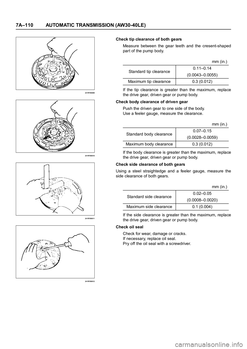
Check tip clearance of both gears
Measure between the gear teeth and the cresent-shaped
par t of the pump body.
If the tip clearance is greater than the maximum, replace
the drive gear, driven gear or pump body.
Check body clearance of driven gear
Push the driven gear to one side of the body.
Use a feeler gauge, measure the clearance.
If the body clearance is greater than the maximum, replace
the drive gear, driven gear or pump body.
Check side clearance of both gears
Using a steel straightedge and a feeler gauge, measure the
side clearance of both gears.
If the side clearance is greater than the maximum, replace
the drive gear, driven gear or pump body.
Check oil seal
Check for wear, damage or cracks.
If necessary, replace oil seal.
Pry off the oil seal with a screwdriver.mm (in.)
Standard tip clearance0.11–0.14
(0.0043–0.0055)
Maximum tip clearance 0.3 (0.012)
mm (in.)
Standard body clearance0.07–0.15
(0.0028–0.0059)
Maximum body clearance 0.3 (0.012)
mm (in.)
Standard side clearance0.02–0.05
(0.0008–0.0020)
Maximum side clearance 0.1 (0.004)
Page 5894 of 6000
AUTOMATIC TRANSMISSION (AW30-40LE) 7A–113
241RY00006
241RY00015
241RY00016
241RY00017
3. Stator shaft
Align the stator shaft with the bolt holes.
Tighten the thir teen bolts.
4. Oil seal ring
Coat the oil seal rings with ATF.
Contract the oil seal rings as shown, and install them onto
the stator shaft.
NOTE:
Do not spread the ring ends too much.
5. O-ring
Coat a new O-ring with ATF and install it to the oil pump
body.
Check oil pump drive gear rotation
Make sure the drive gear rotates smoothly when installed to
the torque converter.Nꞏm (kgꞏm/Ib in)
Torque 11 (1.1/95)
O-ring size (Reference) mm (in.)
Inside diameter 204.9 (8.067)
Thickness 3.5 (0.138)
Page 5896 of 6000
AUTOMATIC TRANSMISSION (AW30-40LE) 7A–115
252L100003
252L100004
252L100005
252L100016
Important operations
Check operation of one-way clutch
Hold the OD direct clutch drum and turn the input shaft.
The input shaft should turn freely clockwise and should lock
counterclockwise.
(1): Free
(2): Lock
1. OD direct clutch assembly
Remove OD direct clutch assembly from OD planetary
gear.
2. Thrust bearing
Then remove thrust bearing with the race from OD direct
clutch drum.
Check piston stroke of OD direct clutch (C-O)
Place the oil pump onto the torque conver ter, and then
place the OD direct clutch assembly onto the oil pump.
Use a dial indicator, measure the OD direct clutch piston
stroke applying and releasing the compressed air (4– 8 kg/
cm
2, 57– 114 psi, 392– 785 kPa) as shown.
mm (in.)
Piston stroke1.85– 2.15
(0.0728– 0.0847)
Page 5905 of 6000
7A–124 AUTOMATIC TRANSMISSION (AW30-40LE)
252L100014
252L100005
252L100016
14. Snap ring
Install snap ring.
Check piston stroke of OD direct clutch (C-0).
Place the oil pump onto the torque converter, and then
place the OD direct clutch assembly onto the oil pump.
Using a dial indicator, measure the OD direct clutch piston
stroke by applying and releasing the compressed air (4– 8
kg/cm
2, 57– 114 psi or 392– 785 kPa) as shown.
If the piston stroke is not within specification, replace the
disc and recheck the piston stroke.
If the piston stroke is non standard, select another flange.
There are six flange sizes.mm (in.)
Piston stroke mm (in.)1.85– 2.15
(0.0728– 0.0847)
mm (in.)
No. Flange thickness No. Flange thickness
16 3.6 (0.142) 19 3.3 (0.130)
17 3.5 (0.138) 20 3.2 (0.126)
18 3.4 (0.134) 21 3.1 (0.122)
Page 5908 of 6000
AUTOMATIC TRANSMISSION (AW30-40LE) 7A–127
252RY00042
252RY00043
252RY00044
252RY00045
Important operations
Check OD brake piston
Place the OD suppor t assembly onto the direct clutch
assembly.
Apply compressed air into the oil passage as shown, and be
sure that the OD brake piston moves smoothly.
4. Snap ring
Place special tool on the spring retainer, and compress the
return spring with a shop press.
Spring compressor: 5-8840-2170-0 (J-37233)
Remove the snap ring with a screwdriver.
6. OD brake piston
Place the OD suppor t onto the direct clutch assembly.
Hold the OD brake piston so it is not slanted and apply
compressed air into the passage to remove the OD brake
piston.
Remove the OD brake piston.
Page 5913 of 6000
7A–132 AUTOMATIC TRANSMISSION (AW30-40LE)
252RY00042
252RY00043
Check OD brake piston
Place the OD suppor t assembly onto the direct clutch
assembly.
Apply compressed air into the oil passage as shown, and be
sure that the OD brake piston moves smoothly.
Page 5935 of 6000
7A–154 AUTOMATIC TRANSMISSION (AW30-40LE)
248RY00051
248RY00052
248RY00053
248RY00054
Important operations
Check operation of No.1 one–way clutch
Hold the planetary sun gear and turn the second brake
hub. The second brake hub should turn freely clockwise
and should lock counterclockwise.
(1) : Free
(2) : Lock
3. Oil seal ring (Metal)
Remove two oil seal rings.
4. Snap ring
Remove the snap ring with snap ring pliers.
INSPECTION AND REPAIR
Check planetary sun gear bushing
Using a dial indicator, measure the inside diameter of the
planetary sun gear bushing.
If the inside diameter is greater than the maximum, replace
the planetary sun gear.mm (in.)
Maximum inside diameter 27.08 (1.0661)
Page 5945 of 6000
7A–164 AUTOMATIC TRANSMISSION (AW30-40LE)
247RY00028
247RY00029
247RY00030
247RY00031
Important operations
3. Oil seal ring
Remove oil seal ring from output shaft.
5. Rear planetary gear assembly
Remove rear planetary gear from rear planetary ring gear.
Check operation of No.2 one–way clutch
Hold the planetary gear and turn the one–way clutch inner
race. The one–way clutch inner race should turn freely
counterclockwise and should lock clockwise.
(1) : Lock
(2) : Free
6. One–way clutch inner race
Remove the one–way clutch inner race from the rear
planetary gear.