1998 OPEL FRONTERA wheel bolt torque
[x] Cancel search: wheel bolt torquePage 3485 of 6000
SUPPLEMENTAL RESTRAINT SYSTEM 9J–48
Passenger Air Bag Assembly
Service Precautions
WARNING: SAFETY PRECAUTIONS MUST BE
FOLLOWED WHEN HANDLING A DEPLOYED AIR
BAG ASSEMBLY. AFTER DEPLOYMENT, THE AIR
BAG ASSEMBLY SURFACE MAY CONTAIN A SMALL
AMOUNT OF SODIUM HYDROXIDE, A BY–PRODUCT
OF THE DEPLOYMENT REACTION, THAT IS
IRRITATING TO THE SKIN AND EYES. MOST OF THE
POWER ON THE AIR BAG ASSEMBLY IS
HARMLESS. AS A PRECAUTION, WEAR GLOVES
AND SAFETY GLASSES WHEN HANDLING A
DEPLOYED AIR BAG ASSEMBLY, AND WASH YOUR
HANDS WITH MILD SOAP AND WATER
AFTERWARDS.
WARNING: WHEN CARRYING A LIVE AIR BAG
ASSEMBLY, MAKE SURE THE BAG AND TRIM
COVER ARE POINTED AWAY FROM YOU. NEVER
CARRY AIR BAG ASSEMBLY BY THE WIRES OR
CONNECTOR ON THE UNDERSIDE OF MODULE. IN
THE CASE OF AN ACCIDENTAL DEPLOYMENT, THE
BAG WILL THEN DEPLOY WITH MINIMAL CHANCE
OF INJURY. WHEN PLACING ALIVE AIR BAG
ASSEMBLY ON A BENCH OR OTHER SURFACE,
ALWAYS FACE BAG AND RIM COVER UP, AWAY
FROM THE SURFACE. NEVER REST A STEERING
COLUMN ASSEMBLY ON THE STEERING WHEEL
WITH THE AIR BAG ASSEMBLY FACE DOWN AND
COLUMN VERTICAL. THIS IS NECESSARY SO THAT
A FREE SPACE IS PROVIDED TO ALLOW THE AIR
BAG ASSEMBLY TO EXPAND IN THE UNLIKELY
EVENT OF ACCIDENTAL DEPLOYMENT.
OTHERWISE, PERSONAL INJURY COULD RESULT.
NOTE: IN THE EVENT DEPLOYMENT HAS
OCCURRED, INSPECT COIL ASSEMBLY WIRE FOR
ANY SIGNS OF SCORCHING, MELTING OR ANY
OTHER DAMAGE DUE TO EXCESSIVE HEAT. IF THE
COIL HAS BEEN DAMAGED, REPLACE IT.
Removal
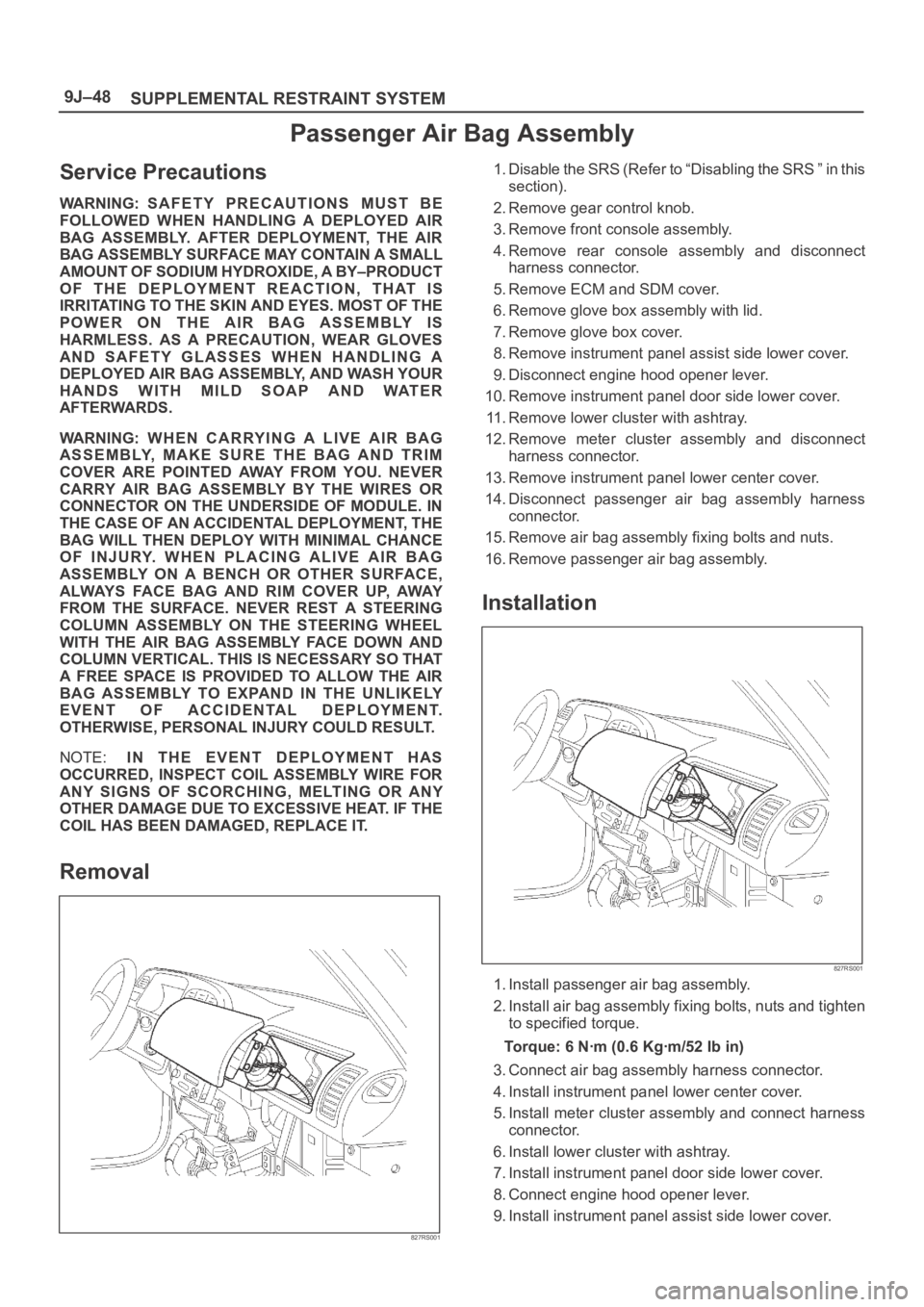
827RS001
1. Disable the SRS (Refer to “Disabling the SRS ” in this
section).
2. Remove gear control knob.
3. Remove front console assembly.
4. Remove rear console assembly and disconnect
harness connector.
5. Remove ECM and SDM cover.
6. Remove glove box assembly with lid.
7. Remove glove box cover.
8. Remove instrument panel assist side lower cover.
9. Disconnect engine hood opener lever.
10. Remove instrument panel door side lower cover.
11. Remove lower cluster with ashtray.
12. Remove meter cluster assembly and disconnect
harness connector.
13. Remove instrument panel lower center cover.
14. Disconnect passenger air bag assembly harness
connector.
15. Remove air bag assembly fixing bolts and nuts.
16. Remove passenger air bag assembly.
Installation
827RS001
1. Install passenger air bag assembly.
2. Install air bag assembly fixing bolts, nuts and tighten
to specified torque.
Torque: 6 Nꞏm (0.6 Kgꞏm/52 Ib in)
3. Connect air bag assembly harness connector.
4. Install instrument panel lower center cover.
5. Install meter cluster assembly and connect harness
connector.
6. Install lower cluster with ashtray.
7. Install instrument panel door side lower cover.
8. Connect engine hood opener lever.
9. Install instrument panel assist side lower cover.
Page 3974 of 6000
DIFFERENTIAL (REAR 220mm)
4A2A–5
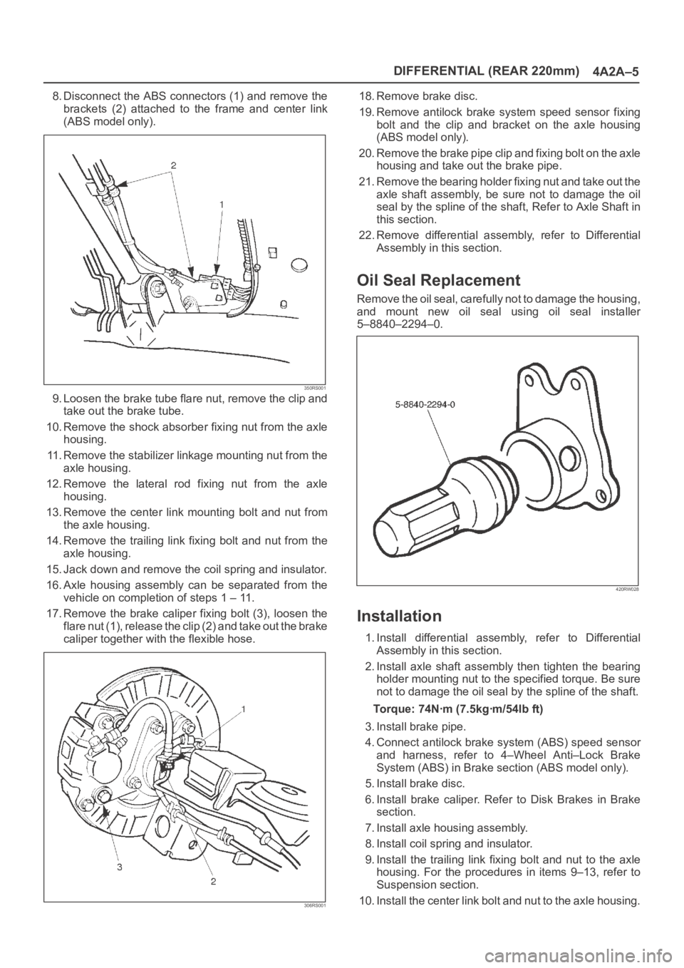
8. Disconnect the ABS connectors (1) and remove the
brackets (2) attached to the frame and center link
(ABS model only).
350RS001
9. Loosen the brake tube flare nut, remove the clip and
take out the brake tube.
10. Remove the shock absorber fixing nut from the axle
housing.
11. Remove the stabilizer linkage mounting nut from the
axle housing.
12. Remove the lateral rod fixing nut from the axle
housing.
13. Remove the center link mounting bolt and nut from
the axle housing.
14. Remove the trailing link fixing bolt and nut from the
axle housing.
15. Jack down and remove the coil spring and insulator.
16. Axle housing assembly can be separated from the
vehicle on completion of steps 1 – 11.
17. Remove the brake caliper fixing bolt (3), loosen the
flare nut (1), release the clip (2) and take out the brake
caliper together with the flexible hose.
306RS001
18. Remove brake disc.
19. Remove antilock brake system speed sensor fixing
bolt and the clip and bracket on the axle housing
(ABS model only).
20. Remove the brake pipe clip and fixing bolt on the axle
housing and take out the brake pipe.
21. Remove the bearing holder fixing nut and take out the
axle shaft assembly, be sure not to damage the oil
seal by the spline of the shaft, Refer to Axle Shaft in
this section.
22. Remove differential assembly, refer to Differential
Assembly in this section.
Oil Seal Replacement
Remove the oil seal, carefully not to damage the housing,
and mount new oil seal using oil seal installer
5–8840–2294–0.
420RW028
Installation
1. Install differential assembly, refer to Differential
Assembly in this section.
2. Install axle shaft assembly then tighten the bearing
holder mounting nut to the specified torque. Be sure
not to damage the oil seal by the spline of the shaft.
Torque: 74Nꞏm (7.5kgꞏm/54lb ft)
3. Install brake pipe.
4. Connect antilock brake system (ABS) speed sensor
and harness, refer to 4–Wheel Anti–Lock Brake
System (ABS) in Brake section (ABS model only).
5. Install brake disc.
6. Install brake caliper. Refer to Disk Brakes in Brake
section.
7. Install axle housing assembly.
8. Install coil spring and insulator.
9. Install the trailing link fixing bolt and nut to the axle
housing. For the procedures in items 9–13, refer to
Suspension section.
10. Install the center link bolt and nut to the axle housing.
Page 4034 of 6000
DIFFERENTIAL (REAR 244mm)
4A2B–27
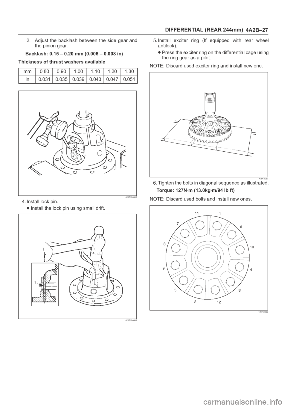
2. Adjust the backlash between the side gear and
the pinion gear.
Backlash: 0.15 – 0.20 mm (0.006 – 0.008 in)
Thickness of thrust washers available
mm
0.800.901.001.101.201.30
in0.0310.0350.0390.0430.0470.051
425RY00008
4. Install lock pin.
Install the lock pin using small drift.
425RY00009
5. Install exciter ring (If equipped with rear wheel
antilock).
Press the exciter ring on the differential cage using
the ring gear as a pilot.
NOTE: Discard used exciter ring and install new one.
425RS052
6. Tighten the bolts in diagonal sequence as illustrated.
Torque: 127Nꞏm (13.0kgꞏm/94 lb ft)
NOTE: Discard used bolts and install new ones.
425RW033
Page 4217 of 6000
4C–11 DRIVE SHAFT SYSTEM
Reassembly
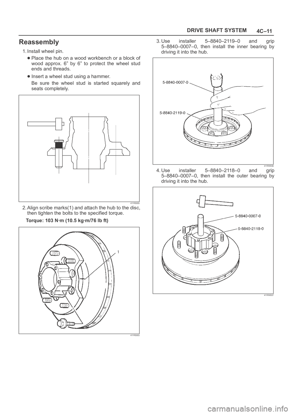
1. Install wheel pin.
Place the hub on a wood workbench or a block of
wood approx. 6” by 6” to protect the wheel stud
ends and threads.
Insert a wheel stud using a hammer.
Be sure the wheel stud is started squarely and
seats completely.
411RS005
2. Align scribe marks(1) and attach the hub to the disc,
then tighten the bolts to the specified torque.
Torque: 103 Nꞏm (10.5 kgꞏm/76 lb ft)
411RS003
3. Use installer 5–8840–2119–0 and grip
5–8840–0007–0, then install the inner bearing by
driving it into the hub.
411RW006
4. Use installer 5–8840–2118–0 and grip
5–8840–0007–0, then install the outer bearing by
driving it into the hub.
411RW007
Page 4218 of 6000
4C–12
DRIVE SHAFT SYSTEM
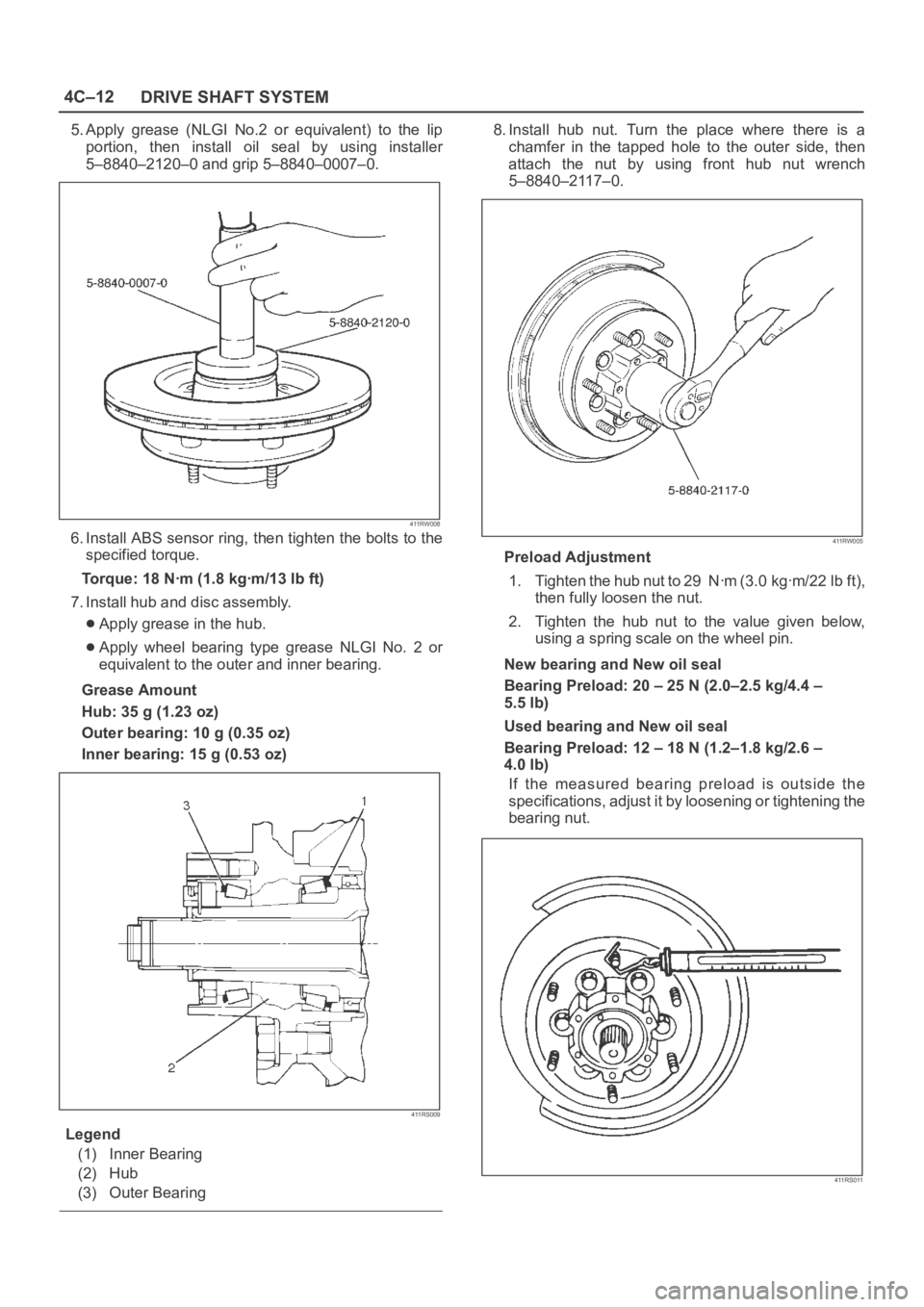
5. Apply grease (NLGI No.2 or equivalent) to the lip
portion, then install oil seal by using installer
5–8840–2120–0 and grip 5–8840–0007–0.
411RW008
6. Install ABS sensor ring, then tighten the bolts to the
specified torque.
Torque: 18 Nꞏm (1.8 kgꞏm/13 lb ft)
7. Install hub and disc assembly.
Apply grease in the hub.
Apply wheel bearing type grease NLGI No. 2 or
equivalent to the outer and inner bearing.
Grease Amount
Hub: 35 g (1.23 oz)
Outer bearing: 10 g (0.35 oz)
Inner bearing: 15 g (0.53 oz)
411RS009
Legend
(1) Inner Bearing
(2) Hub
(3) Outer Bearing
8. Install hub nut. Turn the place where there is a
chamfer in the tapped hole to the outer side, then
attach the nut by using front hub nut wrench
5–8840–2117–0.
411RW005
Preload Adjustment
1. Tighten the hub nut to 29 Nꞏm (3.0 kgꞏm/22 lb ft),
then fully loosen the nut.
2. Tighten the hub nut to the value given below,
using a spring scale on the wheel pin.
New bearing and New oil seal
Bearing Preload: 20 – 25 N (2.0–2.5 kg/4.4 –
5.5 lb)
Used bearing and New oil seal
Bearing Preload: 12 – 18 N (1.2–1.8 kg/2.6 –
4.0 lb)
If the measured bearing preload is outside the
specifications, adjust it by loosening or tightening the
bearing nut.
411RS011
Page 4219 of 6000
4C–13 DRIVE SHAFT SYSTEM
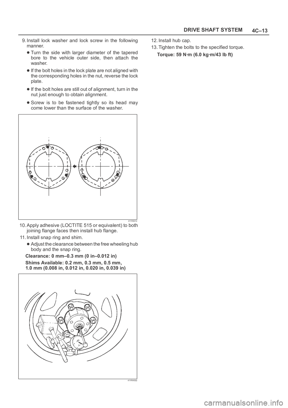
9. Install lock washer and lock screw in the following
manner.
Turn the side with larger diameter of the tapered
bore to the vehicle outer side, then attach the
washer.
If the bolt holes in the lock plate are not aligned with
the corresponding holes in the nut, reverse the lock
plate.
If the bolt holes are still out of alignment, turn in the
nut just enough to obtain alignment.
Screw is to be fastened tightly so its head may
come lower than the surface of the washer.
411RS012
10. Apply adhesive (LOCTITE 515 or equivalent) to both
joining flange faces then install hub flange.
11. Install snap ring and shim.
Adjust the clearance between the free wheeling hub
body and the snap ring.
Clearance: 0 mm–0.3 mm (0 in–0.012 in)
Shims Available: 0.2 mm, 0.3 mm, 0.5 mm,
1.0 mm (0.008 in, 0.012 in, 0.020 in, 0.039 in)
411RW002
12. Install hub cap.
13. Tighten the bolts to the specified torque.
Torque: 59 Nꞏm (6.0 kgꞏm/43 lb ft)
Page 4224 of 6000
4C–18
DRIVE SHAFT SYSTEM
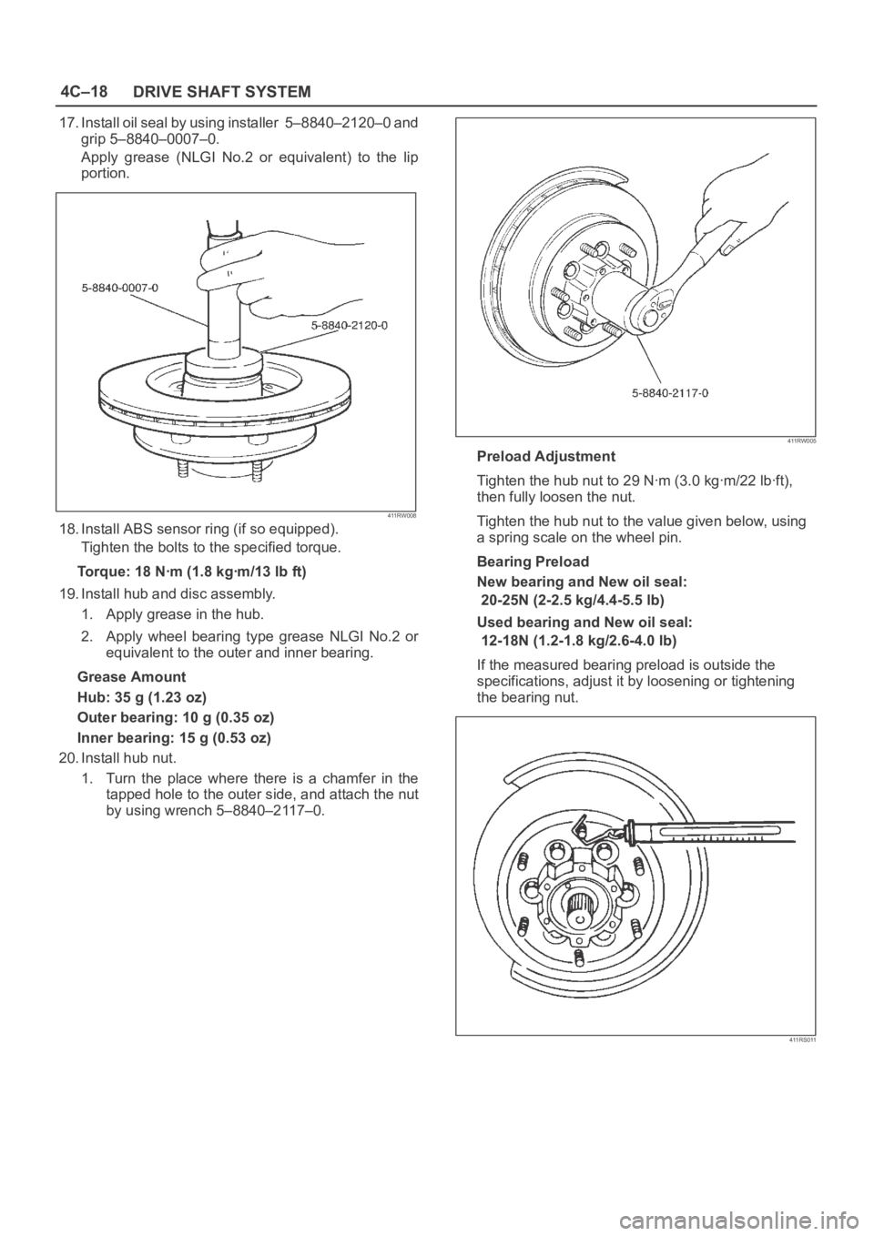
17. Install oil seal by using installer 5–8840–2120–0 and
grip 5–8840–0007–0.
Apply grease (NLGI No.2 or equivalent) to the lip
portion.
411RW008
18. Install ABS sensor ring (if so equipped).
Tighten the bolts to the specified torque.
Torque:18Nꞏm (1.8kgꞏm/13lbft)
19. Install hub and disc assembly.
1. Apply grease in the hub.
2. Apply wheel bearing type grease NLGI No.2 or
equivalent to the outer and inner bearing.
Grease Amount
Hub: 35 g (1.23 oz)
Outer bearing: 10 g (0.35 oz)
Inner bearing: 15 g (0.53 oz)
20. Install hub nut.
1. Turn the place where there is a chamfer in the
tapped hole to the outer side, and attach the nut
by using wrench 5–8840–2117–0.
411RW005
Preload Adjustment
Tighten the hub nut to 29 Nꞏm (3.0 kgꞏm/22 lbꞏft),
then fully loosen the nut.
Tighten the hub nut to the value given below, using
a spring scale on the wheel pin.
Bearing Preload
New bearing and New oil seal:
20-25N (2-2.5 kg/4.4-5.5 lb)
Used bearing and New oil seal:
12-18N (1.2-1.8 kg/2.6-4.0 lb)
If the measured bearing preload is outside the
specifications, adjust it by loosening or tightening
the bearing nut.
411RS011
Page 4225 of 6000
4C–19 DRIVE SHAFT SYSTEM
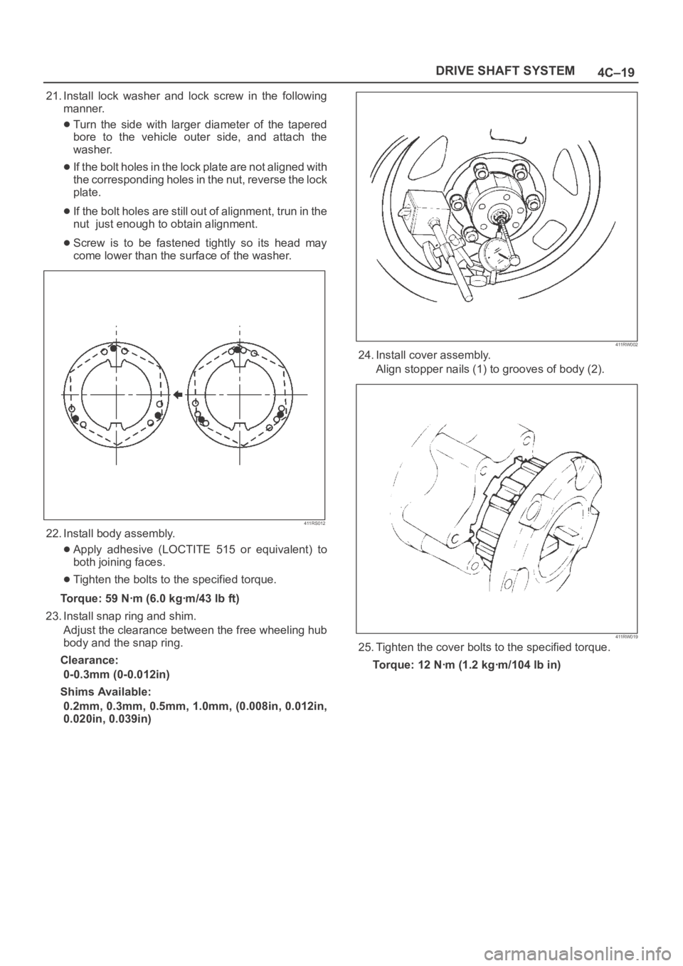
21. Install lock washer and lock screw in the following
manner.
Turn the side with larger diameter of the tapered
bore to the vehicle outer side, and attach the
washer.
If the bolt holes in the lock plate are not aligned with
the corresponding holes in the nut, reverse the lock
plate.
If the bolt holes are still out of alignment, trun in the
nut just enough to obtain alignment.
Screw is to be fastened tightly so its head may
come lower than the surface of the washer.
411RS012
22. Install body assembly.
Apply adhesive (LOCTITE 515 or equivalent) to
both joining faces.
Tighten the bolts to the specified torque.
Torque:59Nꞏm (6.0kgꞏm/43lbft)
23. Install snap ring and shim.
Adjust the clearance between the free wheeling hub
body and the snap ring.
Clearance:
0-0.3mm (0-0.012in)
Shims Available:
0.2mm, 0.3mm, 0.5mm, 1.0mm, (0.008in, 0.012in,
0.020in, 0.039in)
411RW002
24. Install cover assembly.
Align stopper nails (1) to grooves of body (2).
411RW019
25. Tighten the cover bolts to the specified torque.
Torque:12Nꞏm (1.2kgꞏm/104lbin)