1998 OPEL FRONTERA air condition
[x] Cancel search: air conditionPage 848 of 6000

5A–38
BRAKE CONTROL SYSTEM
Chart A-5, TA-5 Braking Sound (From EHCU) Is Heard While Not Braking
StepActionYe sNo
1Is this the first time the vehicle is being driven after starting the
engine?It is self checking
sound.
Normal.
Go to Step 2
2Is vehicle speed under 10 km/h (6 mph)?It is self checking
sound.
Normal.
Go to Step 3
3Check for the following condition:
At the time of shift down or clutch operation.
A t t h e t i m e o f l o w drive (ice or snow road) or rough road drive.
At the time of high-speed turn.
At the time of passing curb.
At the time of operating electrical equipment switches.
At the time of racing the engine (over 5000 rpm).
Did it occur under any one condition above?
ABS may
sometime be
actuated even
when brake pedal
is not applied.
Go to Step 4
4Is there play in each sensor/wheel speed sensor rings?
Go to Step 5
Repair.
Go to Step 7
5Damage or powdered iron sticking to each sensor/wheel speed
sensor ring?
Go to Step 6
Repair.
Go to Step 7
6Is each sensor output normal?(Refer to chart C-1 or TC-1).Check harness/
connector for
suspected
disconnection.
If no
disconnection is
found, replace
EHCU.
Go to Step 7
Repair.
Go to Step 7
7Reconnect all components, ensure all components are properly
mounted.
Was this step finished?Repeat the “Basic
diagnostic flow
chart.”
Go to Step 7
Page 850 of 6000

5A–40
BRAKE CONTROL SYSTEM
Diagnosis By “ABS” Warning Light
Illumination Pattern
In the event that there is abnormality in the “ABS” warning
light illumination pattern while the key is in the ON position
or if the warning light is actuated during driving, trouble
should be diagnosed on a illumination pattern basis as
follows:
No.
Condition“ABS” Warning Light Illumination PatternDiagnostic
1Warning light is actu-
ated normallyNormal
2Warning light is not litWarning light lighting circuit
trouble
Go to Chart B-1
3Warning light remains
ONDiagnostic trouble codes are
stored.
Display diagnostic trouble
codes and diagnose on a
code basis according to the
flow charts.
4Warning light is actu-
ated while drivingDiagnostic trouble codes are
stored.
Display diagnostic trouble
codes and diagnose on a
code basis according to the
flow charts.
Diagnostic Trouble Codes (DTCs)
When the warning light in the meter remains ON, the
EHCU stores the fault identification and disables the
ABS.
1. How to display and erase DTCs:
NOTE:
If DTCs are not displayed, harness C-4 connector
terminal 30 and I-10 connector terminal 2 may be
disconnected. Repair the harness and try DTC
display again.
DTCs can be displayed also by TECH 2. Select mode
“F0: Diagnostic Trouble Codes” from Application
Menu.
1. How to start DTC display:
Confirm that the vehicle has come to a complete
stop (with the wheels standing still) and that the
brake pedal is not depressed. (Unless these two
conditions are satisfied, DTC display cannot be
started.)
With IGN OFF, connect #12 terminal with #4
terminal or # 5 terminal (GND) . Then turn IGN ON.
Page 866 of 6000

5A–56
BRAKE CONTROL SYSTEM
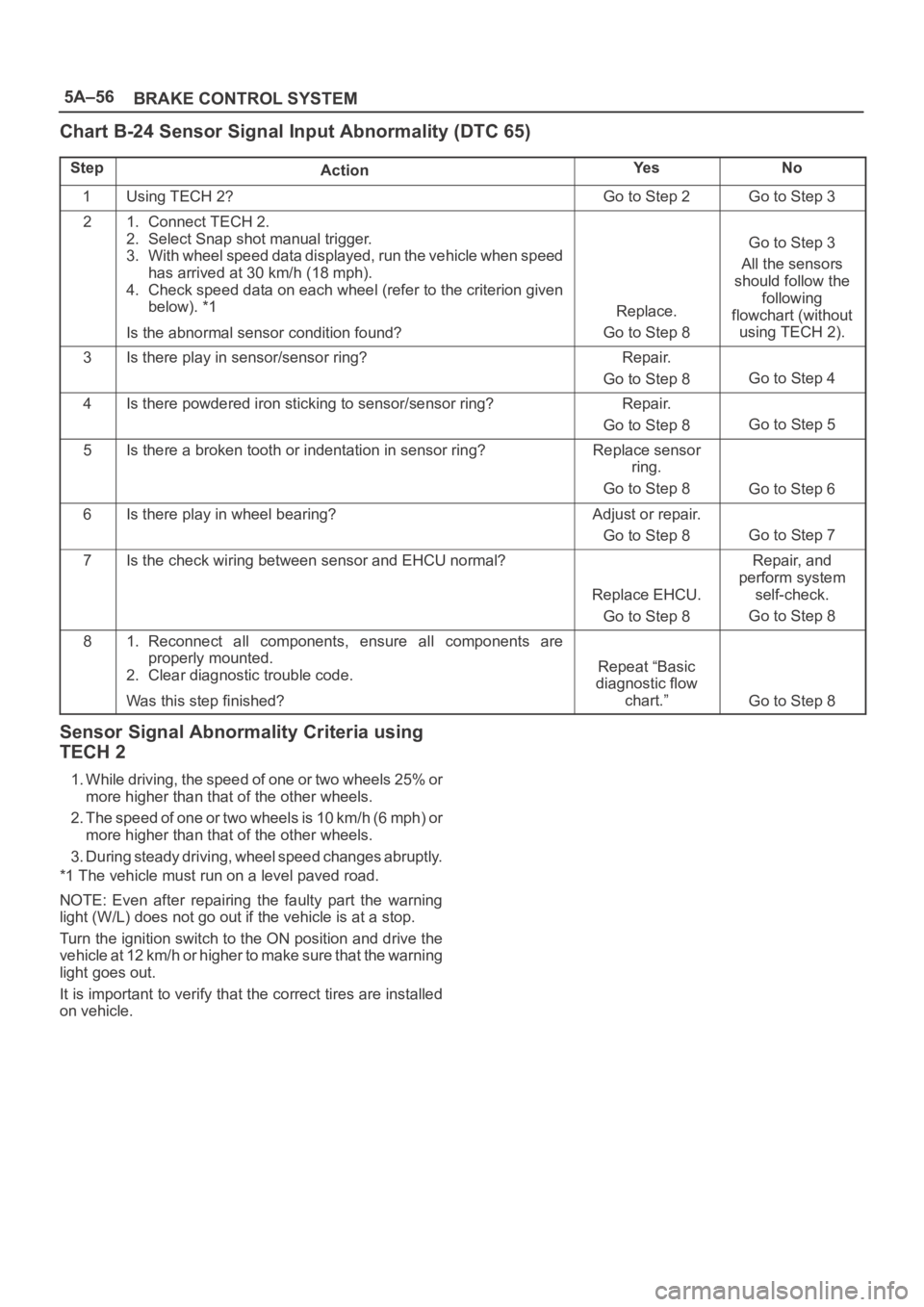
Chart B-24 Sensor Signal Input Abnormality (DTC 65)
StepActionYe sNo
1Using TECH 2?Go to Step 2Go to Step 3
21. Connect TECH 2.
2. Select Snap shot manual trigger.
3. With wheel speed data displayed, run the vehicle when speed
has arrived at 30 km/h (18 mph).
4. Check speed data on each wheel (refer to the criterion given
below). *1
Is the abnormal sensor condition found?
Replace.
Go to Step 8
Go to Step 3
All the sensors
should follow the
following
flowchart (without
using TECH 2).
3Is there play in sensor/sensor ring?Repair.
Go to Step 8
Go to Step 4
4Is there powdered iron sticking to sensor/sensor ring?Repair.
Go to Step 8
Go to Step 5
5Is there a broken tooth or indentation in sensor ring?Replace sensor
ring.
Go to Step 8
Go to Step 6
6Is there play in wheel bearing?Adjust or repair.
Go to Step 8
Go to Step 7
7Is the check wiring between sensor and EHCU normal?
Replace EHCU.
Go to Step 8
Repair, and
perform system
self-check.
Go to Step 8
81. Reconnect all components, ensure all components are
properly mounted.
2. Clear diagnostic trouble code.
Was this step finished?
Repeat “Basic
diagnostic flow
chart.”
Go to Step 8
Sensor Signal Abnormality Criteria using
TECH 2
1. While driving, the speed of one or two wheels 25% or
more higher than that of the other wheels.
2. The speed of one or two wheels is 10 km/h (6 mph) or
more higher than that of the other wheels.
3. During steady driving, wheel speed changes abruptly.
*1 The vehicle must run on a level paved road.
NOTE: Even after repairing the faulty part the warning
light (W/L) does not go out if the vehicle is at a stop.
Turn the ignition switch to the ON position and drive the
vehicle at 12 km/h or higher to make sure that the warning
light goes out.
It is important to verify that the correct tires are installed
on vehicle.
Page 962 of 6000

6A–6
ENGINE MECHANICAL
Rough Engine Idling or Engine Stalling
ConditionPossible causeCorrection
Trouble in fuel injection systemIdle air control valve defectiveReplace
Throttle shutting off incompleteCorrect or replace
Throttle position sensor circuit open
or shortedCorrect or replace
Fuel injector circuits open or shortedCorrect or replace
Fuel injectors damagedReplace
Fuel pump relay defectiveReplace
Mass Airflow Sensor circuit open or
poor connectionsCorrect or replace
Mass Airflow Sensor defectiveReplace
Manifold Absolute Pressure Sensor
circuit open or poor connectionsCorrect or replace
Manifold Absolute Pressure Sensor
defectiveReplace
Engine Coolant Temperature Sensor
circuit open or poor connectionsCorrect or replace
Engine Coolant Temperature Sensor
defectiveReplace
Intake Air Temperature sensor circuit
open or poor connectionsCorrect or replace
Intake Air Temperature sensor
defectiveReplace
Knock Sensor (KS) cable broken or
poor connectionsCorrect or replace
KS defectiveReplace
KS Module circuits open or groundCorrect or replace
KS Module defectiveReplace
Vehicle Speed Sensor circuit open or
shortedCorrect or replace
Vehicle Speed Sensor defectiveReplace
Trouble in emission control systemPowertrain Control Module defectiveReplace
Exhaust Gas Recirculation Valve
circuit open or poor connectionsCorrect or replace
Exhaust Gas Recirculation Valve
faultyReplace
Canister purge valve circuit open or
poor connectionsCorrect or replace
Canister purge valve defectiveReplace
Evaporative Emission Canister
Purge control valve defectiveReplace
Trouble in ignition systemRefer to “Hard Start”
Page 963 of 6000

6A–7
ENGINE MECHANICAL
Condition CorrectionPossible cause
OthersEngine lacks compressionRefer to “Hard Start”
Valve incorrectly seatedLap valve
Air Cleaner Filter cloggedReplace filter element
Valve timing incorrectReadjust
Idle air control valve brokenReplace
Fast idle solenoid defectiveReplace
Positive Crankcase Ventilation valve
defective or cloggedReplace
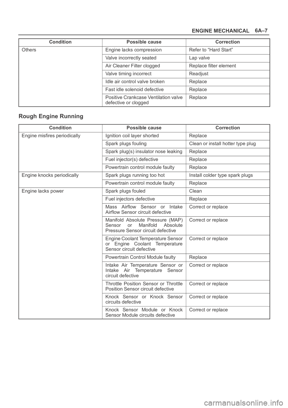
Rough Engine Running
ConditionPossible causeCorrection
Engine misfires periodicallyIgnition coil layer shortedReplace
Spark plugs foulingClean or install hotter type plug
Spark plug(s) insulator nose leakingReplace
Fuel injector(s) defectiveReplace
Powertrain control module faultyReplace
Engine knocks periodicallySpark plugs running too hotInstall colder type spark plugs
Powertrain control module faultyReplace
Engine lacks powerSpark plugs fouledClean
Fuel injectors defectiveReplace
Mass Airflow Sensor or Intake
Airflow Sensor circuit defectiveCorrect or replace
Manifold Absolute Pressure (MAP)
Sensor or Manifold Absolute
Pressure Sensor circuit defectiveCorrect or replace
Engine Coolant Temperature Sensor
or Engine Coolant Temperature
Sensor circuit defectiveCorrect or replace
Powertrain Control Module faultyReplace
Intake Air Temperature Sensor or
Intake Air Temperature Sensor
circuit defectiveCorrect or replace
Throttle Position Sensor or Throttle
Position Sensor circuit defectiveCorrect or replace
Knock Sensor or Knock Sensor
circuits defectiveCorrect or replace
Knock Sensor Module or Knock
Sensor Module circuits defectiveCorrect or replace
Page 964 of 6000

6A–8
ENGINE MECHANICAL
Hesitation
ConditionPossible causeCorrection
Hesitation on accelerationThrottle Position Sensor adjustment
incorrectReplace throttle valve assembly
Throttle Position Sensor circuit open
or shortedCorrect or replace
Excessive play in accelerator linkageAdjust or replace
Mass Airflow Sensor circuit open or
poor connectionsCorrect or replace
Mass Airflow Sensor defectiveReplace
Manifold Absolute Pressure (MAP)
Sensor circuit open or shortedCorrect or replace
MAP Sensor defectiveReplace
Intake Air Temperature (IAT) Sensor
circuit open or shortedCorrect or replace
Knock Sensor (KS) Circuit open or
poor connectionsCorrect or replace
KS defectiveReplace
KS Module circuits open or shortedCorrect or replace
KS Module defectiveReplace
IAT Sensor defectiveReplace
Hesitation at high speedsFuel tank strainer cloggedClean or replace
(Fuel pressure too low)Fuel pipe cloggedClean or replace
Fuel filter cloggedReplace
Defective fuel pump systemCheck and replace
Fuel Pressure Control Valve leakingReplace
Hesitation at high speeds
(Fuel injector not working normally)Power supply or ground circuit for
Multiport Fuel Injection System
shorted or openCheck and correct or replace
Fuel Injector defectiveReplace
Cable of Multiport Fuel Injection
System circuit open or poor
connectionsCorrect or replace
Page 965 of 6000

6A–9
ENGINE MECHANICAL
Condition CorrectionPossible cause
Hesitation at high speedsPowertrain Control Module defectiveReplace
Throttle Position Sensor cable
broken or poor connectionsCorrect or replace
Throttle Position Sensor defectiveReplace
Engine Coolant Temperature Sensor
circuit open or shortedCorrect or replace
Engine Coolant Temperature Sensor
defectiveReplace
Mass Airflow Sensor circuit open or
poor connectionsCorrect or replace
Mass Airflow Sensor defectiveReplace
MAP Sensor cable broken or poor
connectionsCorrect or replace
MAP Sensor defectiveReplace
IAT Sensor circuit open or poor
connectionsCorrect or replace
IAT Sensor defectiveReplace
KS circuit open or poor connectionsCorrect or replace
KS defectiveReplace
KS Module circuit open or shortedCorrect or replace
KS Module defectiveReplace
Throttle valve not fully openedCheck and correct or replace
Air Cleaner Filter cloggedReplace filter element
Power supply voltage too lowCheck and correct or replace
Page 966 of 6000

6A–10
ENGINE MECHANICAL
Engine Lacks Power
ConditionPossible causeCorrection
Trouble in fuel systemFuel Pressure Control Valve not
working normallyReplace
Fuel injector cloggedClean or replace
Fuel pipe cloggedClean
Fuel filter clogged or fouledReplace
Fuel pump drive circuit not working
normallyCorrect or replace
Fuel tank not sufficiently breathing
due to clogged Evaporative
Emission Control System circuitClean or replace
Water in fuel systemClean
Inferior quality fuel in fuel systemUse fuel of specified octane rating
Powertrain Control Module supplied
poor voltageCorrect circuit
Throttle Position Sensor cable
broken or poor connectionsCorrect or replace
Throttle Position Sensor defectiveReplace
Mass Airflow Sensor not working
normallyReplace
Manifold Absolute Pressure Sensor
not working normallyReplace
Intake Air Temperature Sensor not
working normallyReplace
Engine Coolant Temperature Sensor
circuit open or shortedCorrect or replace
Engine Coolant Temperature Sensor
defectiveReplace
Powertrain Control Module defectiveReplace
Trouble in intake or exhaust systemAir Cleaner Filter cloggedReplace filter element
Air duct kinked or flattenedCorrect or replace
Ignition failure————Refer to Hard Start Troubleshooting
Guide
Heat range of spark plug inadequateInstall spark plugs of adequate heat
range
Ignition coil defectiveReplace