1998 OPEL FRONTERA air condition
[x] Cancel search: air conditionPage 247 of 6000

C-25
0.5 BR
C-25
X-5X-5
X-5X-5
2 1
4 3
0.5 P/G FL-1 MAIN
80A
C-20
10A A/C
0.5 G/W 0.5 G/O
C-25E-27H-16
Pressure
switch
Relay:
Air conditioning
thermostat
Automatic heater/air conditioner
control unitRelay:
Air conditioning
0.5 BR
1
2
I-3214
Fan “ON”
I-32X-5
E-271
Magnet
clutch
B-36
B-36
H-1616
D08RY00183
Page 281 of 6000

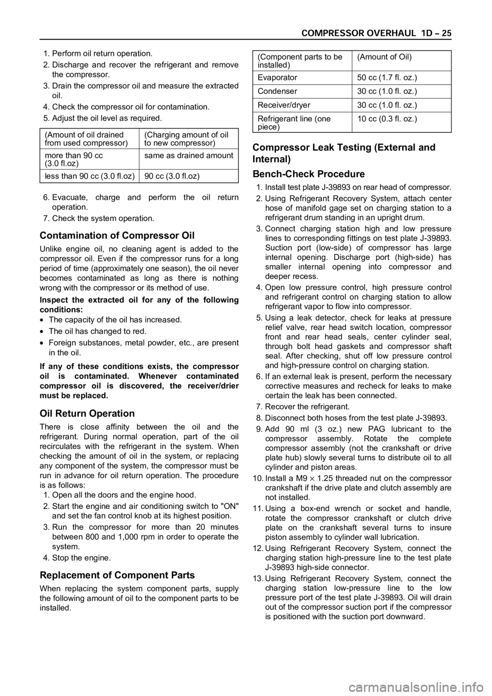
1. Perform oil return operation.
2. Discharge and recover the refrigerant and remove
the compressor.
3. Drain the compressor oil and measure the extracted
oil.
4. Check the compressor oil for contamination.
5. Adjust the oil level as required.
6. Evacuate, charge and perform the oil return
operation.
7. Check the system operation.
Contamination of Compressor Oil
Unlike engine oil, no cleaning agent is added to the
compressor oil. Even if the compressor runs for a long
period of time (approximately one season), the oil never
becomes contaminated as long as there is nothing
wrong with the compressor or its method of use.
Inspect the extracted oil for any of the following
conditions:
The capacity of the oil has increased.
The oil has changed to red.
Foreign substances, metal powder, etc., are present
in the oil.
If any of these conditions exists, the compressor
oil is contaminated. Whenever contaminated
compressor oil is discovered, the receiver/drier
must be replaced.
Oil Return Operation
There is close affinity between the oil and the
refrigerant. During normal operation, part of the oil
recirculates with the refrigerant in the system. When
checking the amount of oil in the system, or replacing
any component of the system, the compressor must be
run in advance for oil return operation. The procedure
is as follows:
1. Open all the doors and the engine hood.
2. Start the engine and air conditioning switch to "ON"
and set the fan control knob at its highest position.
3. Run the compressor for more than 20 minutes
between 800 and 1,000 rpm in order to operate the
system.
4. Stop the engine.
Replacement of Component Parts
When replacing the system component parts, supply
the following amount of oil to the component parts to be
installed.
Compressor Leak Testing (External and
Internal)
Bench-Check Procedure
1. Install test plate J-39893 on rear head of compressor.
2. Using Refrigerant Recovery System, attach center
hose of manifold gage set on charging station to a
refrigerant drum standing in an upright drum.
3. Connect charging station high and low pressure
lines to corresponding fittings on test plate J-39893.
Suction port (low-side) of compressor has large
internal opening. Discharge port (high-side) has
smaller internal opening into compressor and
deeper recess.
4. Open low pressure control, high pressure control
and refrigerant control on charging station to allow
refrigerant vapor to flow into compressor.
5. Using a leak detector, check for leaks at pressure
relief valve, rear head switch location, compressor
front and rear head seals, center cylinder seal,
through bolt head gaskets and compressor shaft
seal. After checking, shut off low pressure control
and high-pressure control on charging station.
6. If an external leak is present, perform the necessary
corrective measures and recheck for leaks to make
certain the leak has been connected.
7. Recover the refrigerant.
8. Disconnect both hoses from the test plate J-39893.
9. Add 90 ml (3 oz.) new PAG lubricant to the
compressor assembly. Rotate the complete
compressor assembly (not the crankshaft or drive
plate hub) slowly several turns to distribute oil to all
cylinder and piston areas.
10. Install a M9
1.25 threaded nut on the compressor
crankshaft if the drive plate and clutch assembly are
not installed.
11. Using a box-end wrench or socket and handle,
rotate the compressor crankshaft or clutch drive
plate on the crankshaft several turns to insure
piston assembly to cylinder wall lubrication.
12. Using Refrigerant Recovery System, connect the
charging station high-pressure line to the test plate
J-39893 high-side connector.
13. Using Refrigerant Recovery System, connect the
charging station low-pressure line to the low
pressure port of the test plate J-39893. Oil will drain
out of the compressor suction port if the compressor
is positioned with the suction port downward. (Component parts to be (Amount of Oil)
installed)
Evaporator 50 cc (1.7 fl. oz.)
Condenser 30 cc (1.0 fl. oz.)
Receiver/dryer 30 cc (1.0 fl. oz.)
Refrigerant line (one 10 cc (0.3 fl. oz.)
piece)
(Amount of oil drained (Charging amount of oil
from used compressor) to new compressor)
more than 90 cc same as drained amount
(3.0 fl.oz)
less than 90 cc (3.0 fl.oz) 90 cc (3.0 fl.oz)
Page 439 of 6000

DIFFERENTIAL (FRONT) 4A1–2
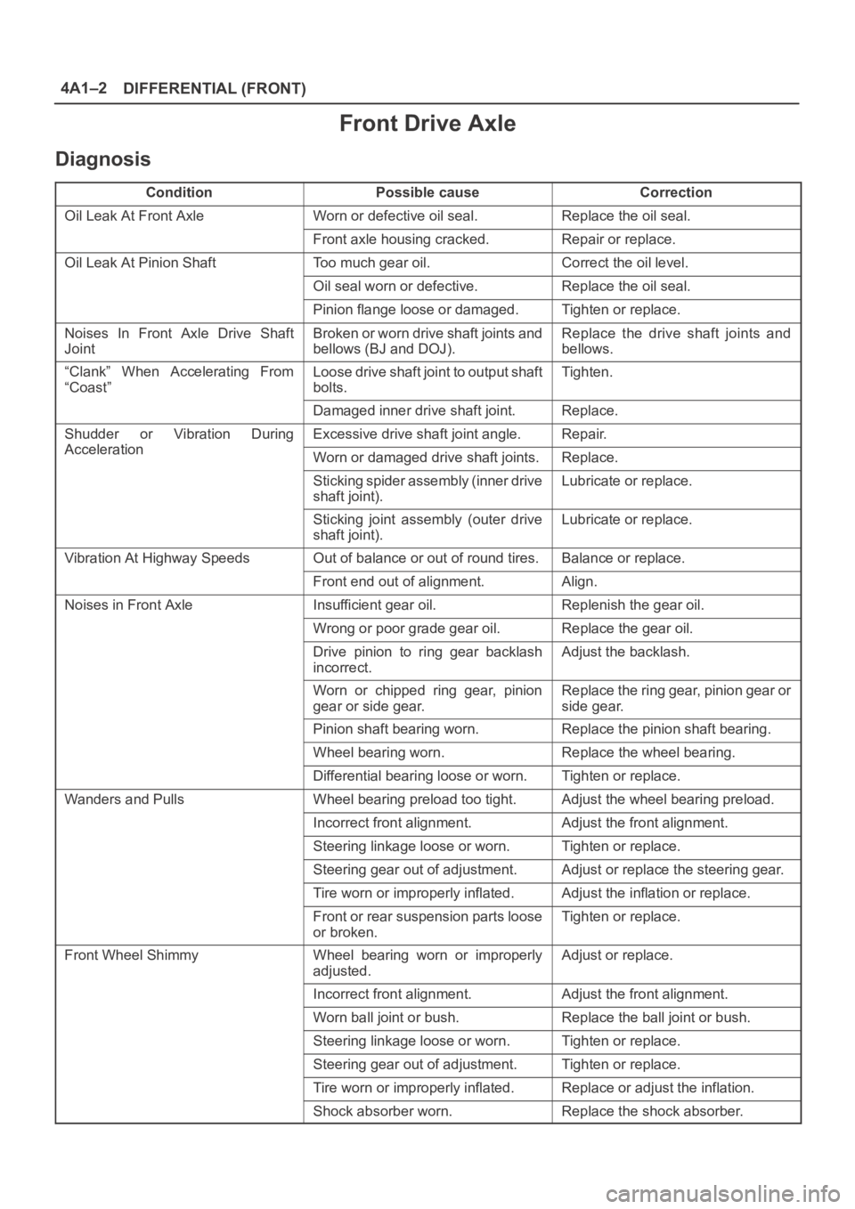
Front Drive Axle
Diagnosis
ConditionPossible causeCorrection
Oil Leak At Front AxleWorn or defective oil seal.Replace the oil seal.
Front axle housing cracked.Repair or replace.
Oil Leak At Pinion ShaftToo much gear oil.Correct the oil level.
Oil seal worn or defective.Replace the oil seal.
Pinion flange loose or damaged.Tighten or replace.
Noises In Front Axle Drive Shaft
JointBroken or worn drive shaft joints and
bellows (BJ and DOJ).Replace the drive shaft joints and
bellows.
“Clank” When Accelerating From
“Coast”Loose drive shaft joint to output shaft
bolts.Tighten.
Damaged inner drive shaft joint.Replace.
Shudder or Vibration During
Acceleration
Excessive drive shaft joint angle.Repair.
AccelerationWorn or damaged drive shaft joints.Replace.
Sticking spider assembly (inner drive
shaft joint).Lubricate or replace.
Sticking joint assembly (outer drive
shaft joint).Lubricate or replace.
Vibration At Highway SpeedsOut of balance or out of round tires.Balance or replace.
Front end out of alignment.Align.
Noises in Front AxleInsufficient gear oil.Replenish the gear oil.
Wrong or poor grade gear oil.Replace the gear oil.
Drive pinion to ring gear backlash
incorrect.Adjust the backlash.
Worn or chipped ring gear, pinion
gear or side gear.Replace the ring gear, pinion gear or
side gear.
Pinion shaft bearing worn.Replace the pinion shaft bearing.
Wheel bearing worn.Replace the wheel bearing.
Differential bearing loose or worn.Tighten or replace.
Wanders and PullsWheel bearing preload too tight.Adjust the wheel bearing preload.
Incorrect front alignment.Adjust the front alignment.
Steering linkage loose or worn.Tighten or replace.
Steering gear out of adjustment.Adjust or replace the steering gear.
Tire worn or improperly inflated.Adjust the inflation or replace.
Front or rear suspension parts loose
or broken.Tighten or replace.
Front Wheel ShimmyWheel bearing worn or improperly
adjusted.Adjust or replace.
Incorrect front alignment.Adjust the front alignment.
Worn ball joint or bush.Replace the ball joint or bush.
Steering linkage loose or worn.Tighten or replace.
Steering gear out of adjustment.Tighten or replace.
Tire worn or improperly inflated.Replace or adjust the inflation.
Shock absorber worn.Replace the shock absorber.
Page 441 of 6000

DIFFERENTIAL (FRONT) 4A1–4
3. Remove the front propeller shaft. Refer to Front
Propeller Shaft in this section.
4. Remove flange nut by using pinion flange holder
5–8840–2157–0.
425RW045
5. Remove flange.
6. Remove oil seal.
7. Remove outer bearing by using remover
5–8840–2323–0.
415RW022
8. Remove collapsible spacer.
Inspection and Repair
Make necessary correction or parts replacement if wear,
damage, corrosion or any other abnormal conditions are
found through inspection.
Check the following parts:
1. Seal surface of the pinion.
2. Cage bore for burns.
Installation
1. Install collapsible spacer. Discard the used
collapsible spacer and install a new one.
2. Install outer bearing.
NOTE: Do not drive in, but just temporarily set in the outer
bearing by hand, which should be indirectly pressed in
finally by tightening the flange nut.
3. Install oil seal, use oil seal installer 9–8522–1275–0 to
install a new oil seal that has been soaked in axle
lubricant.
415RW021
4. Install flange.
5. Install flange nut, refer to Differential Assembly for
flange nut reassembly in this section.
NOTE: Discard the used nut and install a new one.
Page 459 of 6000

DIFFERENTIAL (FRONT) 4A1–22
4. Remove the cross pin, using a soft metal rod and a
hammer.
425RS043
5. Remove pinion gear.
6. Remove side gear.
7. Remove thrust washer.
Inspection and Repair
Make necessary correction or parts replacement if wear,
damage, corrosion or any other abnormal conditions are
found through inspection.
Check the following parts:
1. Ring gear, pinion gear
2. Bearing
3. Side gear, pinion gear, cross pin
4. Differential cage, carrier
5. Thrust washer
6. Oil seal
Ring gear replacement:
1. The ring gear should always be replaced with the
drive pinion as a set.
2. Clean the ring gear threaded holes to remove the
locking agent.
3. When installing the ring gear, apply LOCTITE 271 or
equivalent to all the threaded area and half of the
unthreaded area of the bolt.
4. Discard used bolts and install new ones.
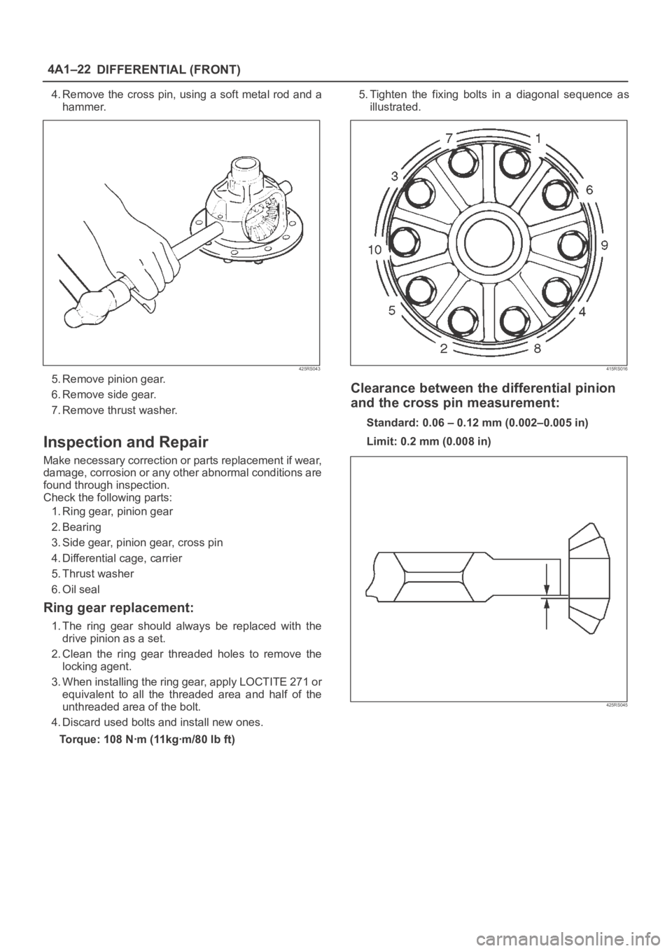
Torque: 108 Nꞏm (11kgꞏm/80 lb ft)5. Tighten the fixing bolts in a diagonal sequence as
illustrated.
415RS016
Clearance between the differential pinion
and the cross pin measurement:
Standard: 0.06 – 0.12 mm (0.002–0.005 in)
Limit: 0.2 mm (0.008 in)
425RS045
Page 470 of 6000

DIFFERENTIAL (REAR 220mm)
4A2A–3
Diagnosis
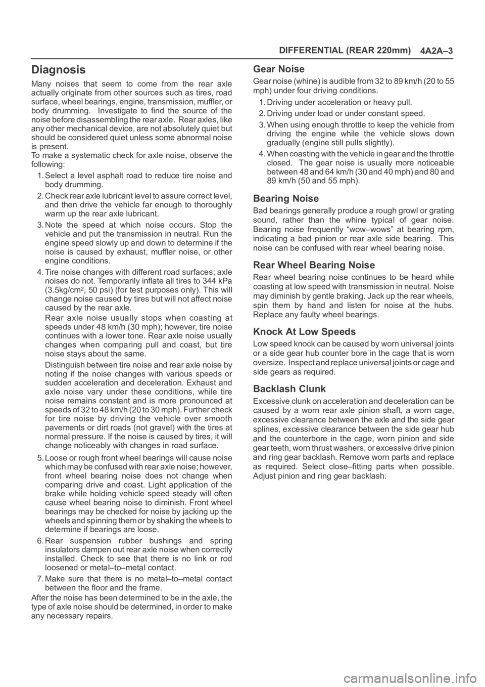
Many noises that seem to come from the rear axle
actually originate from other sources such as tires, road
surface, wheel bearings, engine, transmission, muffler, or
body drumming. Investigate to find the source of the
noise before disassembling the rear axle. Rear axles, like
any other mechanical device, are not absolutely quiet but
should be considered quiet unless some abnormal noise
is present.
To make a systematic check for axle noise, observe the
following:
1. Select a level asphalt road to reduce tire noise and
body drumming.
2. Check rear axle lubricant level to assure correct level,
and then drive the vehicle far enough to thoroughly
warm up the rear axle lubricant.
3. Note the speed at which noise occurs. Stop the
vehicle and put the transmission in neutral. Run the
engine speed slowly up and down to determine if the
noise is caused by exhaust, muffler noise, or other
engine conditions.
4. Tire noise changes with different road surfaces; axle
noises do not. Temporarily inflate all tires to 344 kPa
(3.5kg/cm
2, 50 psi) (for test purposes only). This will
change noise caused by tires but will not affect noise
caused by the rear axle.
Rear axle noise usually stops when coasting at
speeds under 48 km/h (30 mph); however, tire noise
continues with a lower tone. Rear axle noise usually
changes when comparing pull and coast, but tire
noise stays about the same.
Distinguish between tire noise and rear axle noise by
noting if the noise changes with various speeds or
sudden acceleration and deceleration. Exhaust and
axle noise vary under these conditions, while tire
noise remains constant and is more pronounced at
speeds of 32 to 48 km/h (20 to 30 mph). Further check
for tire noise by driving the vehicle over smooth
pavements or dirt roads (not gravel) with the tires at
normal pressure. If the noise is caused by tires, it will
change noticeably with changes in road surface.
5. Loose or rough front wheel bearings will cause noise
which may be confused with rear axle noise; however,
front wheel bearing noise does not change when
comparing drive and coast. Light application of the
brake while holding vehicle speed steady will often
cause wheel bearing noise to diminish. Front wheel
bearings may be checked for noise by jacking up the
wheels and spinning them or by shaking the wheels to
determine if bearings are loose.
6. Rear suspension rubber bushings and spring
insulators dampen out rear axle noise when correctly
installed. Check to see that there is no link or rod
loosened or metal–to–metal contact.
7. Make sure that there is no metal–to–metal contact
between the floor and the frame.
After the noise has been determined to be in the axle, the
type of axle noise should be determined, in order to make
any necessary repairs.
Gear Noise
Gear noise (whine) is audible from 32 to 89 km/h (20 to 55
mph) under four driving conditions.
1. Driving under acceleration or heavy pull.
2. Driving under load or under constant speed.
3. When using enough throttle to keep the vehicle from
driving the engine while the vehicle slows down
gradually (engine still pulls slightly).
4. When coasting with the vehicle in gear and the throttle
closed. The gear noise is usually more noticeable
between 48 and 64 km/h (30 and 40 mph) and 80 and
89 km/h (50 and 55 mph).
Bearing Noise
Bad bearings generally produce a rough growl or grating
sound, rather than the whine typical of gear noise.
Bearing noise frequently “wow–wows” at bearing rpm,
indicating a bad pinion or rear axle side bearing. This
noise can be confused with rear wheel bearing noise.
Rear Wheel Bearing Noise
Rear wheel bearing noise continues to be heard while
coasting at low speed with transmission in neutral. Noise
may diminish by gentle braking. Jack up the rear wheels,
spin them by hand and listen for noise at the hubs.
Replace any faulty wheel bearings.
Knock At Low Speeds
Low speed knock can be caused by worn universal joints
or a side gear hub counter bore in the cage that is worn
oversize. Inspect and replace universal joints or cage and
side gears as required.
Backlash Clunk
Excessive clunk on acceleration and deceleration can be
caused by a worn rear axle pinion shaft, a worn cage,
excessive clearance between the axle and the side gear
splines, excessive clearance between the side gear hub
and the counterbore in the cage, worn pinion and side
gear teeth, worn thrust washers, or excessive drive pinion
and ring gear backlash. Remove worn parts and replace
as required. Select close–fitting parts when possible.
Adjust pinion and ring gear backlash.
Page 474 of 6000

DIFFERENTIAL (REAR 220mm)
4A2A–7
3. Remove flange nut and washer by using pinion flange
holder 5–8840–2157–0 after raising up its staked
parts completely.
415RW028
4. Remove flange.
5. Remove oil seal.
6. Remove outer bearing by using remover
5–8840–2323–0.
425RW066
7. Remove collapsible spacer.
Inspection and Repair
Make necessary correction or parts replacement if wear,
damage, corrosion or any other abnormal conditions are
found through inspection.
Check the following parts:
1. Seal surface of the pinion.
2. Cage bore for burns.
Installation
1. Install collapsible spacer, discard the used collapsible
spacer and install a new one.
2. Install outer bearing.
NOTE: Do not drive in, but just temporarily set in the outer
bearing by hand, which should be indirectly pressed in
finally by tightening the flange nut.
3. By using the seal installer 5–8840–2165–0, install a
new oil seal (1) that has grease on seal lip.
425RW050
4. Install flange.
5. Install flange nut and washer. Refer to Differential
Assembly in this section for flange nut reassembly.
NOTE: Discard the used nut and install a new one.
Page 489 of 6000

4A2A–22
DIFFERENTIAL (REAR 220mm)
4. Remove the cross pin, using a soft metal rod and a
hammer.
425RS043
5. Remove pinion gear.
6. Remove side gear.
7. Remove thrust washer.
Inspection and Repair
Make necessary correction or parts replacement if wear,
damage, corrosion or any other abnormal conditions are
found through inspection.
Check the following parts:
1. Ring gear, pinion gear
2. Bearing
3. Side gear, pinion gear, cross pin
4. Differential cage, carrier
5. Thrust washer
6. Oil seal
Ring gear replacement:
1. The ring gear should always be replaced with the
drive pinion as a set.
2. Clean the ring gear threaded holes to remove the
locking agent.
3. When installing the ring gear, apply LOCTITE 271 or
equivalent to all the threaded area and half of the
unthreaded area of the bolt.
4. Discard used bolts and install new ones.
Torque: 108 Nꞏm (11.0kgꞏm/80 lb ft)5. Tighten the fixing bolts in a diagonal sequence as
illustrated.
415RW036
Clearance between the differential pinion
and the cross pin measurement:
Standard: 0.06 – 0.12 mm (0.002–0.005 in)
Limit: 0.2 mm (0.008 in)
425RS045