1998 OPEL FRONTERA Electrical
[x] Cancel search: ElectricalPage 1192 of 6000
6E–75 ENGINE DRIVEABILITY AND EMISSIONS
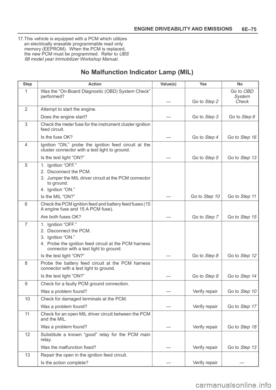
17.This vehicle is equipped with a PCM which utilizes
an electrically erasable programmable read only
memory (EEPROM). When the PCM is replaced,
the new PCM must be programmed. Refer to
UBS
98 model year Immobilizer Workshop Manual.
No Malfunction Indicator Lamp (MIL)
StepActionVa l u e ( s )Ye sNo
1Was the “On-Board Diagnostic (OBD) System Check”
performed?
—Go to Step 2
Go to OBD
System
Check
2Attempt to start the engine.
Does the engine start?
—Go to Step 3Go to Step 6
3Check the meter fuse for the instrument cluster ignition
feed circuit.
Is the fuse OK?
—Go to Step 4Go to Step 16
4Ignition “ON,” probe the ignition feed circuit at the
cluster connector with a test light to ground.
Is the test light “ON?”
—Go to Step 5Go to Step 13
51. Ignition “OFF.”
2. Disconnect the PCM.
3. Jumper the MIL driver circuit at the PCM connector
to ground.
4. Ignition “ON.”
Is the MIL “ON?”
—Go to Step 10Go to Step 11
6Check the PCM ignition feed and battery feed fuses (15
A engine fuse and 15 A PCM fuse).
Are both fuses OK?
—Go to Step 7Go to Step 15
71. Ignition “OFF.”
2. Disconnect the PCM.
3. Ignition “ON.”
4. Probe the ignition feed circuit at the PCM harness
connector with a test light to ground.
Is the test light “ON?”
—Go to Step 8Go to Step 12
8Probe the battery feed circuit at the PCM harness
connector with a test light to ground.
Is the test light “ON?”
—Go to Step 9Go to Step 14
9Check for a faulty PCM ground connection.
Was a problem found?
—Verify repairGo to Step 10
10Check for damaged terminals at the PCM.
Was a problem found?
—Verify repairGo to Step 17
11Check for an open MIL driver circuit between the PCM
and the MIL.
Was a problem found?
—Verify repairGo to Step 18
12Substitute a known “good” relay for the PCM main
relay.
Was the malfunction fixed?
—Verify repairGo to Step 13
13Repair the open in the ignition feed circuit.
Is the action complete?
—Verify repair—
Page 1193 of 6000
6E–76
ENGINE DRIVEABILITY AND EMISSIONS
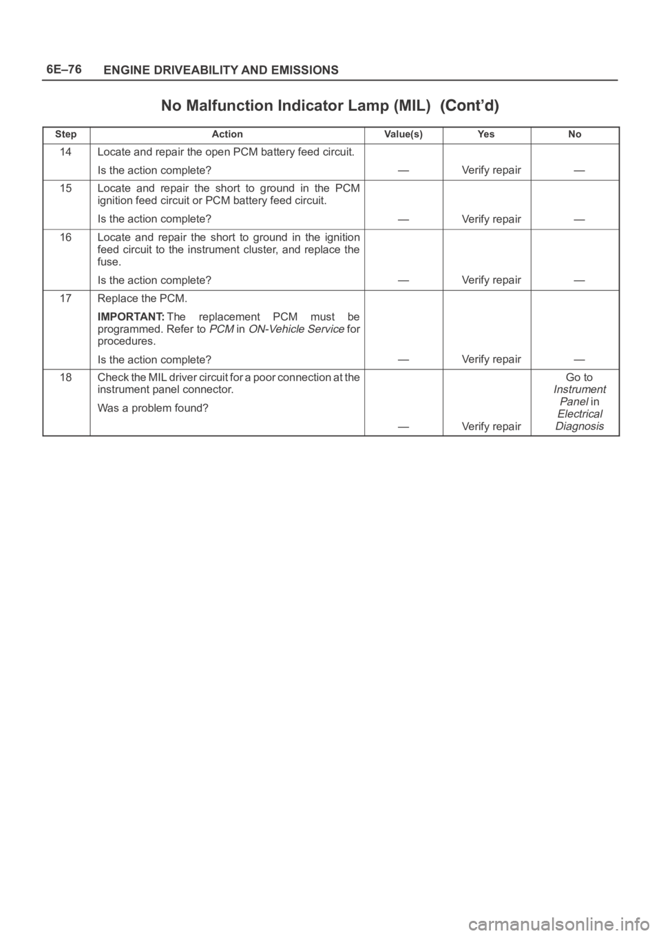
No Malfunction Indicator Lamp (MIL)
StepNo Ye s Va l u e ( s ) Action
14Locate and repair the open PCM battery feed circuit.
Is the action complete?
—Verify repair—
15Locate and repair the short to ground in the PCM
ignition feed circuit or PCM battery feed circuit.
Is the action complete?
—Verify repair—
16Locate and repair the short to ground in the ignition
feed circuit to the instrument cluster, and replace the
fuse.
Is the action complete?
—Verify repair—
17Replace the PCM.
IMPORTANT:The replacement PCM must be
programmed. Refer to
PCM in ON-Vehicle Service for
procedures.
Is the action complete?
—Verify repair—
18Check the MIL driver circuit for a poor connection at the
instrument panel connector.
Was a problem found?
—Verify repair
Go to
Instrument
Panel
in
Electrical
Diagnosis
Page 1194 of 6000
6E–77 ENGINE DRIVEABILITY AND EMISSIONS
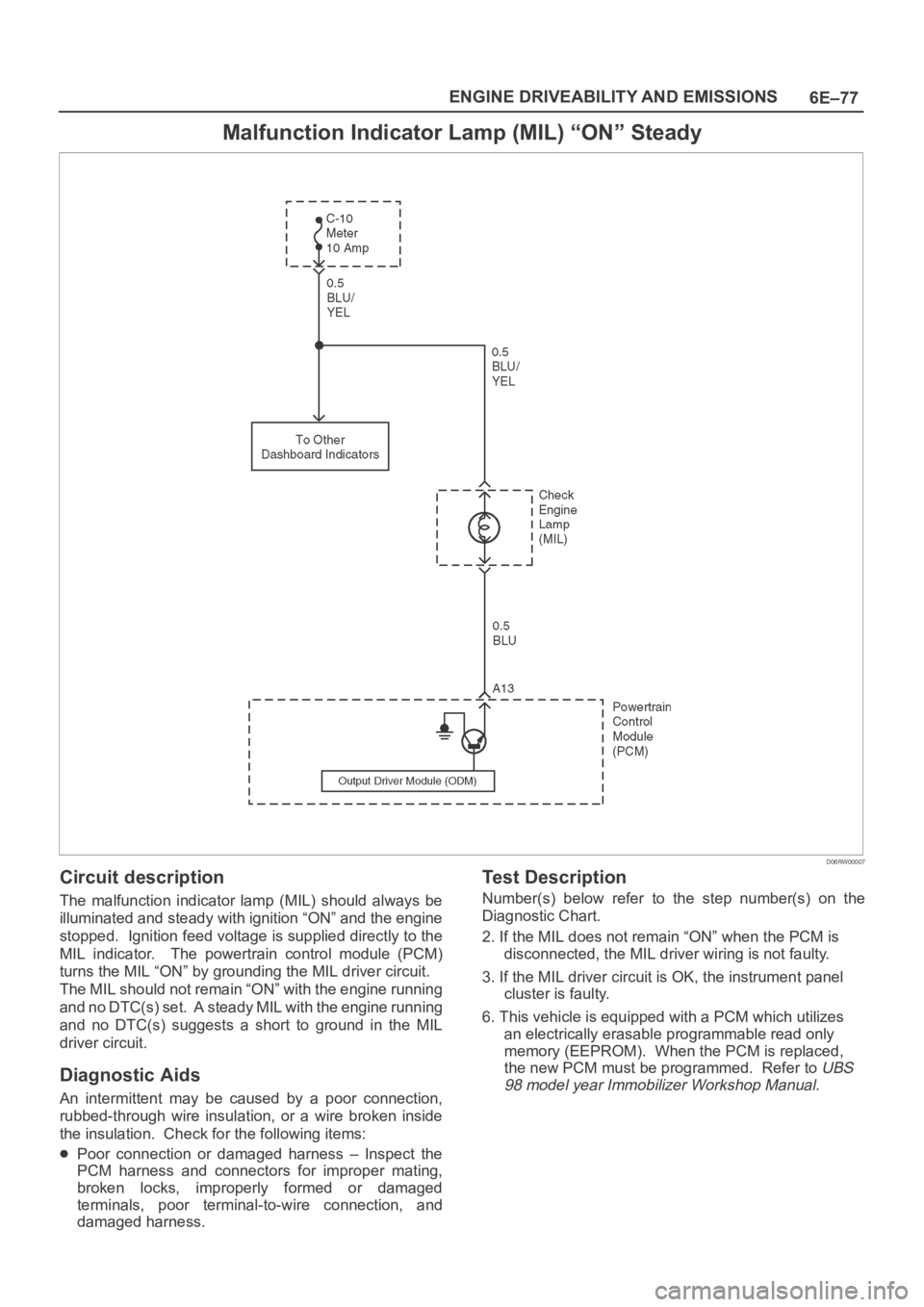
Malfunction Indicator Lamp (MIL) “ON” Steady
D06RW00007
Circuit description
The malfunction indicator lamp (MIL) should always be
illuminated and steady with ignition “ON” and the engine
stopped. Ignition feed voltage is supplied directly to the
MIL indicator. The powertrain control module (PCM)
turns the MIL “ON” by grounding the MIL driver circuit.
The MIL should not remain “ON” with the engine running
and no DTC(s) set. A steady MIL with the engine running
and no DTC(s) suggests a short to ground in the MIL
driver circuit.
Diagnostic Aids
An intermittent may be caused by a poor connection,
rubbed-through wire insulation, or a wire broken inside
the insulation. Check for the following items:
Poor connection or damaged harness – Inspect the
PCM harness and connectors for improper mating,
broken locks, improperly formed or damaged
terminals, poor terminal-to-wire connection, and
damaged harness.
Test Description
Number(s) below refer to the step number(s) on the
Diagnostic Chart.
2. If the MIL does not remain “ON” when the PCM is
disconnected, the MIL driver wiring is not faulty.
3. If the MIL driver circuit is OK, the instrument panel
cluster is faulty.
6. This vehicle is equipped with a PCM which utilizes
an electrically erasable programmable read only
memory (EEPROM). When the PCM is replaced,
the new PCM must be programmed. Refer to
UBS
98 model year Immobilizer Workshop Manual.
Page 1198 of 6000
6E–81 ENGINE DRIVEABILITY AND EMISSIONS
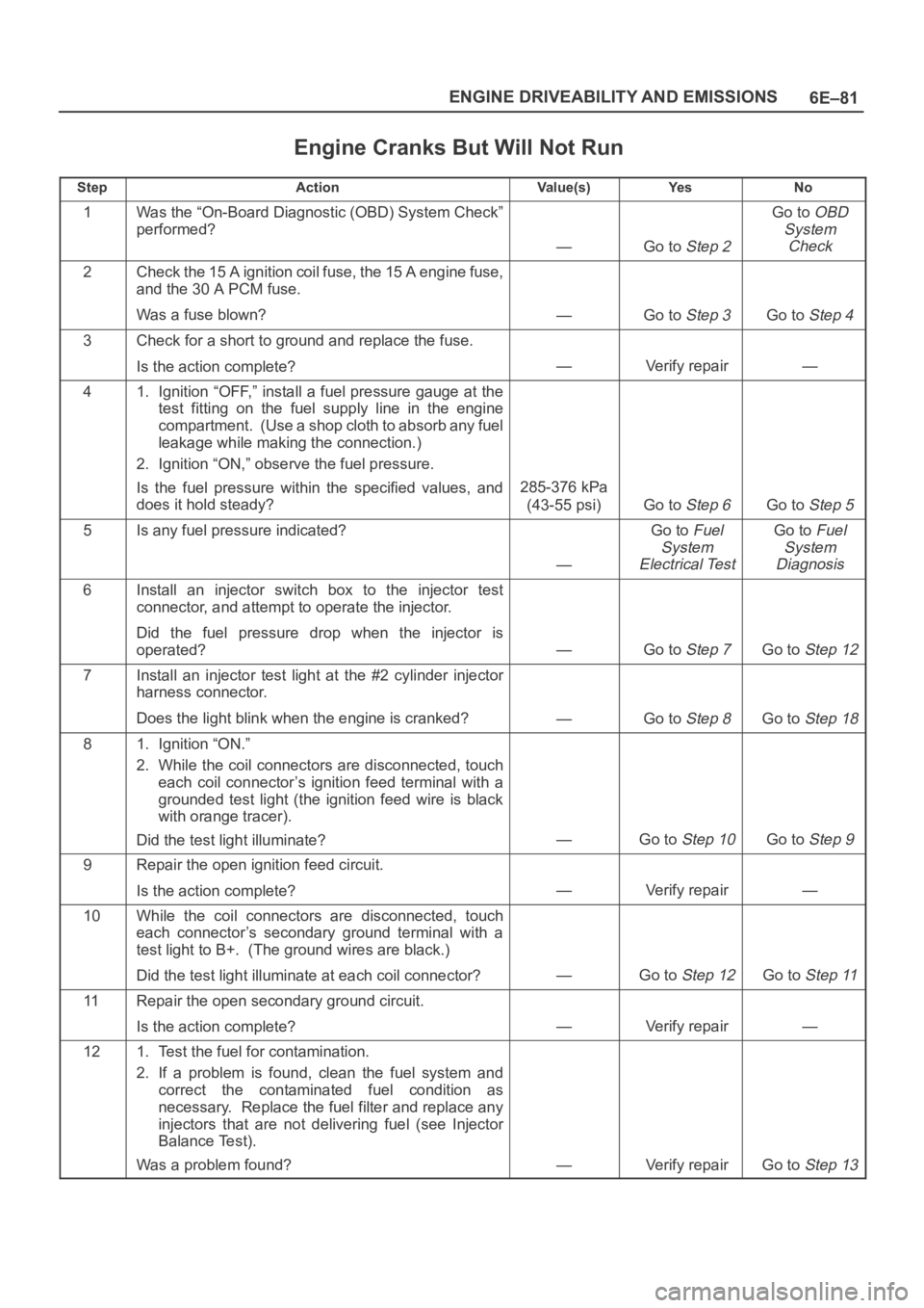
Engine Cranks But Will Not Run
StepActionVa l u e ( s )Ye sNo
1Was the “On-Board Diagnostic (OBD) System Check”
performed?
—Go to Step 2
Go to OBD
System
Check
2Check the 15 A ignition coil fuse, the 15 A engine fuse,
and the 30 A PCM fuse.
Was a fuse blown?
—Go to Step 3Go to Step 4
3Check for a short to ground and replace the fuse.
Is the action complete?
—Verify repair—
41. Ignition “OFF,” install a fuel pressure gauge at the
test fitting on the fuel supply line in the engine
compartment. (Use a shop cloth to absorb any fuel
leakage while making the connection.)
2. Ignition “ON,” observe the fuel pressure.
Is the fuel pressure within the specified values, and
does it hold steady?
285-376 kPa
(43-55 psi)
Go to Step 6Go to Step 5
5Is any fuel pressure indicated?
—
Go to Fuel
System
Electrical TestGo to Fuel
System
Diagnosis
6Install an injector switch box to the injector test
connector, and attempt to operate the injector.
Did the fuel pressure drop when the injector is
operated?
—Go to Step 7Go to Step 12
7Install an injector test light at the #2 cylinder injector
harness connector.
Does the light blink when the engine is cranked?
—Go to Step 8Go to Step 18
81. Ignition “ON.”
2. While the coil connectors are disconnected, touch
each coil connector’s ignition feed terminal with a
grounded test light (the ignition feed wire is black
with orange tracer).
Did the test light illuminate?
—Go to Step 10Go to Step 9
9Repair the open ignition feed circuit.
Is the action complete?
—Verify repair—
10While the coil connectors are disconnected, touch
each connector’s secondary ground terminal with a
test light to B+. (The ground wires are black.)
Did the test light illuminate at each coil connector?
—Go to Step 12Go to Step 11
11Repair the open secondary ground circuit.
Is the action complete?
—Verify repair—
121. Test the fuel for contamination.
2. If a problem is found, clean the fuel system and
correct the contaminated fuel condition as
necessary. Replace the fuel filter and replace any
injectors that are not delivering fuel (see Injector
Balance Test).
Was a problem found?
—Verify repairGo to Step 13
Page 1202 of 6000
6E–85 ENGINE DRIVEABILITY AND EMISSIONS
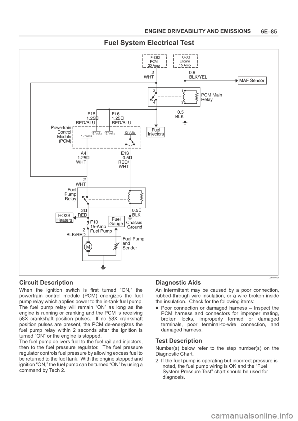
Fuel System Electrical Test
D06RW101
Circuit Description
When the ignition switch is first turned “ON,” the
powertrain control module (PCM) energizes the fuel
pump relay which applies power to the in-tank fuel pump.
The fuel pump relay will remain “ON” as long as the
engine is running or cranking and the PCM is receiving
58X crankshaft position pulses. If no 58X crankshaft
position pulses are present, the PCM de-energizes the
fuel pump relay within 2 seconds after the ignition is
turned “ON” or the engine is stopped.
The fuel pump delivers fuel to the fuel rail and injectors,
then to the fuel pressure regulator. The fuel pressure
regulator controls fuel pressure by allowing excess fuel to
be returned to the fuel tank. With the engine stopped and
ignition “ON,” the fuel pump can be turned “ON” by using a
command by Tech 2.
Diagnostic Aids
An intermittent may be caused by a poor connection,
rubbed-through wire insulation, or a wire broken inside
the insulation. Check for the following items:
Poor connection or damaged harness – Inspect the
PCM harness and connectors for improper mating,
broken locks, improperly formed or damaged
terminals, poor terminal-to-wire connection, and
damaged harness.
Test Description
Number(s) below refer to the step number(s) on the
Diagnostic Chart.
2. If the fuel pump is operating but incorrect pressure is
noted, the fuel pump wiring is OK and the “Fuel
System Pressure Test” chart should be used for
diagnosis.
Page 1203 of 6000
6E–86
ENGINE DRIVEABILITY AND EMISSIONS
CAUTION: To reduce the risk of fire and personal
injury:
It is necessary to relieve fuel system pressure
before connecting a fuel pressure gauge. Refer to
Fuel Pressure Relief Procedure, below.
A small amount of fuel may be released when
disconnecting the fuel lines. Cover fuel line
fittings with a shop towel before disconnecting, to
catch any fuel that may leak out. Place the towel in
an approved container when the disconnect is
completed.
Fuel Pressure Relief Procedure
1. Remove the fuel cap.
2. Remove the fuel pump relay from the underhood
relay center.
3. Start the engine and allow it to stall.
4. Crank the engine for an additional 3 seconds.
Fuel Gauge Installation
1. Remove the shoulder fitting cap.
2. Install fuel gauge 5-8840-0378-0 to the fuel feed line
located in front of and above the right side valve train
cover .
3. Reinstall the fuel pump relay.
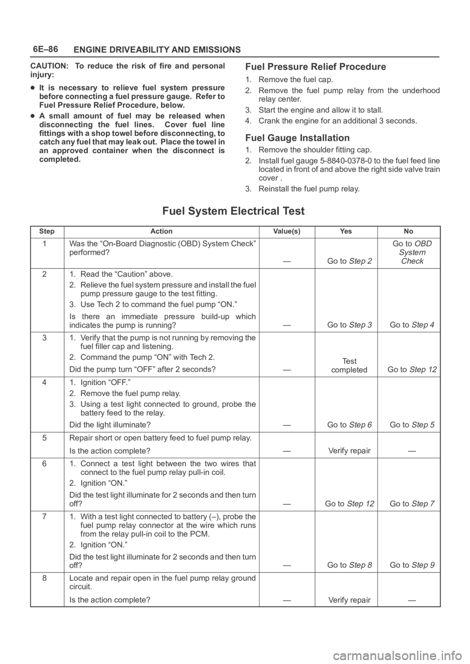
Fuel System Electrical Test
StepActionVa l u e ( s )Ye sNo
1Was the “On-Board Diagnostic (OBD) System Check”
performed?
—Go to Step 2
Go to OBD
System
Check
21. Read the “Caution” above.
2. Relieve the fuel system pressure and install the fuel
pump pressure gauge to the test fitting.
3. Use Tech 2 to command the fuel pump “ON.”
Is there an immediate pressure build-up which
indicates the pump is running?
—Go to Step 3Go to Step 4
31. Verify that the pump is not running by removing the
fuel filler cap and listening.
2. Command the pump “ON” with Tech 2.
Did the pump turn “OFF” after 2 seconds?
—
Te s t
completed
Go to Step 12
41. Ignition “OFF.”
2. Remove the fuel pump relay.
3. Using a test light connected to ground, probe the
battery feed to the relay.
Did the light illuminate?
—Go to Step 6Go to Step 5
5Repair short or open battery feed to fuel pump relay.
Is the action complete?
—Verify repair—
61. Connect a test light between the two wires that
connect to the fuel pump relay pull-in coil.
2. Ignition “ON.”
Did the test light illuminate for 2 seconds and then turn
off?
—Go to Step 12Go to Step 7
71. With a test light connected to battery (–), probe the
fuel pump relay connector at the wire which runs
from the relay pull-in coil to the PCM.
2. Ignition “ON.”
Did the test light illuminate for 2 seconds and then turn
off?
—Go to Step 8Go to Step 9
8Locate and repair open in the fuel pump relay ground
circuit.
Is the action complete?
—Verify repair—
Page 1204 of 6000
6E–87 ENGINE DRIVEABILITY AND EMISSIONS
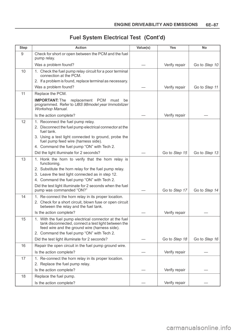
Fuel System Electrical Test
StepNo Ye s Va l u e ( s ) Action
9Check for short or open between the PCM and the fuel
pump relay.
Was a problem found?
—Verify repairGo to Step 10
101. Check the fuel pump relay circuit for a poor terminal
connection at the PCM.
2. If a problem is found, replace terminal as necessary.
Was a problem found?
—Verify repairGo to Step 11
11Replace the PCM.
IMPORTANT:The replacement PCM must be
programmed. Refer to
UBS 98model year Immobilizer
Workshop Manual.
Is the action complete?—Verify repair—
121. Reconnect the fuel pump relay.
2. Disconnect the fuel pump electrical connector at the
fuel tank.
3. Using a test light connected to ground, probe the
fuel pump feed wire (harness side).
4. Command the fuel pump “ON” with Tech 2.
Did the light illuminate for 2 seconds?
—Go to Step 15Go to Step 13
131. Honk the horn to verify that the horn relay is
functioning.
2. Substitute the horn relay for the fuel pump relay.
3. Leave the test light connected as in step 12.
4. Command the fuel pump “ON” with Tech 2.
Did the test light illuminate for 2 seconds when the fuel
pump was commanded “ON?”
—Go to Step 17Go to Step 14
141. Re-connect the horn relay in its proper location.
2. Check for a short circuit, blown fuse or open circuit
between the relay and the fuel tank.
Is the action complete?
—Verify repair—
151. With the fuel pump electrical connector at the fuel
tank disconnected, connect a test light between the
feed wire and the ground wire (harness side).
2. Command the fuel pump “ON” with Tech 2.
Did the test light illuminate for 2 seconds?
—Go to Step 18Go to Step 16
16Repair the open circuit in the fuel pump ground wire.
Is the action complete?
—Verify repair—
171. Re-connect the horn relay in its proper location.
2. Replace the fuel pump relay.
Is the action complete?
—Verify repair—
18Replace the fuel pump.
Is the action complete?
—Verify repair—
Page 1209 of 6000
6E–92
ENGINE DRIVEABILITY AND EMISSIONS
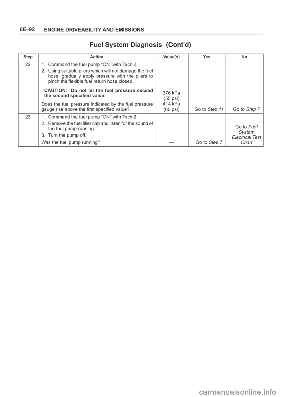
Fuel System Diagnosis
StepNo Ye s Va l u e ( s ) Action
221. Command the fuel pump “ON” with Tech 2.
2. Using suitable pliers which will not damage the fuel
hose, gradually apply pressure with the pliers to
pinch the flexible fuel return hose closed.
CAUTION: Do not let the fuel pressure exceed
the second specified value.
Does the fuel pressure indicated by the fuel pressure
gauge rise above the first specified value?
376 kPa
(55 psi)
414 kPa
(60 psi)
Go to Step 11Go to Step 7
231. Command the fuel pump “ON” with Tech 2.
2. Remove the fuel filler cap and listen for the sound of
the fuel pump running.
3. Turn the pump off.
Was the fuel pump running?
—Go to Step 7
Go to Fuel
System
Electrical Test
Chart