Page 4021 of 6000
4A2B–14DIFFERENTIAL (REAR 244mm)
Disassembled View
415RY00002
Legend
(1) Flange Nut and Washer
(2) Flange
(3) Oil Seal
(4) Outer Bearing
(5) Outer Bearing Outer Race
(6) Diff Carrier
(7) Bearing Cap
(8) Bolt(9) Inner Bearing Outer Race
(10) Collapsible Spacer
(11) Inner Bearing
(12) Adjust Shim (Pinion Position)
(13) Drive Pinion Shaft
(14) Adjust Shim (Diff Cage Assembly)
(15) Diff Preload/Backlash
(16) Side Bearing
(17) Side Bearing Outer Race
Page 4025 of 6000

4A2B–18DIFFERENTIAL (REAR 244mm)
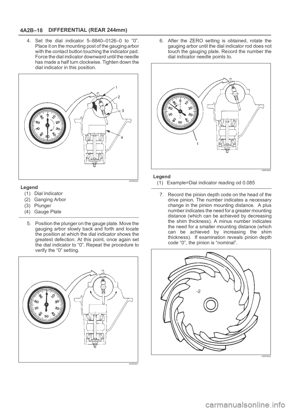
4. Set the dial indicator 5–8840–0126–0 to “0”.
Place it on the mounting post of the gauging arbor
with the contact button touching the indicator pad.
Force the dial indicator downward until the needle
has made a half turn clockwise. Tighten down the
dial indicator in this position.
425RS020
Legend
(1) Dial Indicator
(2) Ganging Arbor
(3) Plunger
(4) Gauge Plate
5. Position the plunger on the gauge plate. Move the
gauging arbor slowly back and forth and locate
the position at which the dial indicator shows the
greatest defection. At this point, once again set
the dial indicator to “0”. Repeat the procedure to
verify the “0” setting.
425RS021
6. After the ZERO setting is obtained, rotate the
gauging arbor until the dial indicator rod does not
touch the gauging plate. Record the number the
dial indicator needle points to.
425RS022
Legend
(1) Example=Dial indicator reading od 0.085
7. Record the pinion depth code on the head of the
drive pinion. The number indicates a necessary
change in the pinion mounting distance. A plus
number indicates the need for a greater mounting
distance (which can be achieved by decreasing
the shim thickness). A minus number indicates
the need for a smaller mounting distance (which
can be achieved by increasing the shim
thickness). If examination reveals pinion depth
code “0”, the pinion is “nominal”.
425RS023
Page 4028 of 6000
DIFFERENTIAL (REAR 244mm)
4A2B–21
4. Using punch 5–8840–2293–0, stake the flange
nut at two points.
NOTE: When staking, be sure to turn the nut to ensure
that there is no change in bearing preload. Make sure of
preload again as instructed in 3).
425RW062
11. Adjust ring gear backlash.
1. Attach the side bearing to the differential
assembly without shims by using installer
5–8840–2050–0 and grip 5–8840–0007–0.
425RW063
2. Insert the differential cage assembly with bearing
outer races into the side bearing bores of the
carrier.
425RS030
3. Using two sets of feeler gauges, insert a feeler
stock of sufficient thickness between each
bearing outer race and the carrier to remove all
end play. Make certain the feeler stock is pushed
to the bottom of the bearing bores.
Mount the dial indicator 5–8840–0126–0 on the
carrier so that the indicator stem is at right angles to
a tooth on the ring gear.
425RW049
Page 4029 of 6000
4A2B–22DIFFERENTIAL (REAR 244mm)
4. Adjust feeler gauge thickness from side to side
until ring gear backlash is in the specified range.
Backlash: 0.13– 0.2mm (0.005– 0.008in)
425RS032With zero end play and correct backlash
established, remove the feeler gauge packs,
determine the thickness of the shims required and
add 0.05 mm (0.002 in) to each shim pack to
provide side bearing preload. Always use new
shims.
5. Remove side bearing by using remover
5–8840–2587–0 and adapter 5–8840–2576–0.
415RW041
12. Install the side bearings together with the selected
shims by using installer 5–8840–2050–0 (2) and grip
5–8840–0007–0 (1).
425RW032
13. Install side bearing outer race.
14. Install differential cage assembly.
15. Align the setting marks (1) applied at disassembly
then install the bearing cap.
425RS035
Page 4034 of 6000
DIFFERENTIAL (REAR 244mm)
4A2B–27
2. Adjust the backlash between the side gear and
the pinion gear.
Backlash: 0.15 – 0.20 mm (0.006 – 0.008 in)
Thickness of thrust washers available
mm
0.800.901.001.101.201.30
in0.0310.0350.0390.0430.0470.051
425RY00008
4. Install lock pin.
Install the lock pin using small drift.
425RY00009
5. Install exciter ring (If equipped with rear wheel
antilock).
Press the exciter ring on the differential cage using
the ring gear as a pilot.
NOTE: Discard used exciter ring and install new one.
425RS052
6. Tighten the bolts in diagonal sequence as illustrated.
Torque: 127Nꞏm (13.0kgꞏm/94 lb ft)
NOTE: Discard used bolts and install new ones.
425RW033
Page 4039 of 6000

4A2B–32DIFFERENTIAL (REAR 244mm)
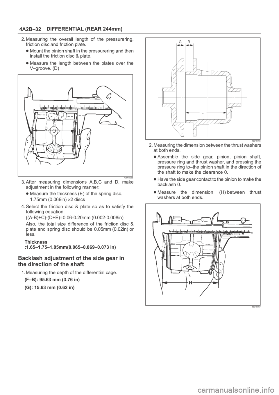
2. Measuring the overall length of the pressurering,
friction disc and friction plate.
Mount the pinion shaft in the pressurering and then
install the friction disc & plate.
Measure the length between the plates over the
V–groove. (D)
425RS065
3. After measuring dimensions A,B,C and D, make
adjustment in the following manner:
Measure the thickness (E) of the spring disc.
1.75mm (0.069in)
2discs
4. Select the friction disc & plate so as to satisfy the
following equation:
{(A-B)+C}-(D+E)=0.06-0.20mm (0.002-0.008in)
Also, the total size difference of the friction disc &
plate and spring disc should be 0.05mm (0.02in) or
less.
Thickness
:1.65–1.75–1.85mm(0.065–0.069–0.073 in)
Backlash adjustment of the side gear in
the direction of the shaft
1. Measuring the depth of the differential cage.
(F–B): 95.63 mm (3.76 in)
(G): 15.63 mm (0.62 in)
425RS066
2. Measuring the dimension between the thrust washers
at both ends.
Assemble the side gear, pinion, pinion shaft,
pressure ring and thrust washer, and pressing the
pressure ring to–the pinion shaft in the direction of
the shaft to make the clearance 0.
Have the side gear contact to the pinion to make the
backlash 0.
Measure the dimension (H) between thrust
washers at both ends.
425RS067
Page 4040 of 6000

DIFFERENTIAL (REAR 244mm)
4A2B–33
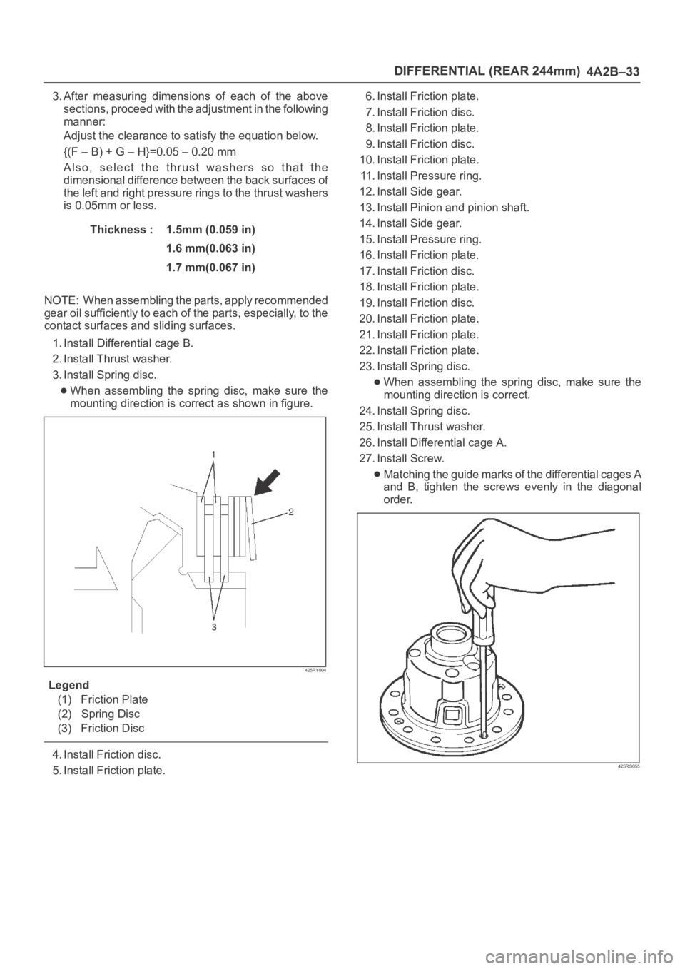
3. After measuring dimensions of each of the above
sections, proceed with the adjustment in the following
manner:
Adjust the clearance to satisfy the equation below.
{(F – B) + G – H}=0.05 – 0.20 mm
Also, select the thrust washers so that the
dimensional difference between the back surfaces of
the left and right pressure rings to the thrust washers
is 0.05mm or less.
Thickness : 1.5mm (0.059 in)
1.6 mm(0.063 in)
1.7 mm(0.067 in)
NOTE: When assembling the parts, apply recommended
gear oil sufficiently to each of the parts, especially, to the
contact surfaces and sliding surfaces.
1. Install Differential cage B.
2. Install Thrust washer.
3. Install Spring disc.
When assembling the spring disc, make sure the
mounting direction is correct as shown in figure.
425RY004
Legend
(1) Friction Plate
(2) Spring Disc
(3) Friction Disc
4. Install Friction disc.
5. Install Friction plate.6. Install Friction plate.
7. Install Friction disc.
8. Install Friction plate.
9. Install Friction disc.
10. Install Friction plate.
11. Install Pressure ring.
12. Install Side gear.
13. Install Pinion and pinion shaft.
14. Install Side gear.
15. Install Pressure ring.
16. Install Friction plate.
17. Install Friction disc.
18. Install Friction plate.
19. Install Friction disc.
20. Install Friction plate.
21. Install Friction plate.
22. Install Friction plate.
23. Install Spring disc.
When assembling the spring disc, make sure the
mounting direction is correct.
24. Install Spring disc.
25. Install Thrust washer.
26. Install Differential cage A.
27. Install Screw.
Matching the guide marks of the differential cages A
and B, tighten the screws evenly in the diagonal
order.
425RS055
Page 4056 of 6000

4B1–11 DRIVE LINE CONTROL SYSTEM (SHIFT ON THE FLY)
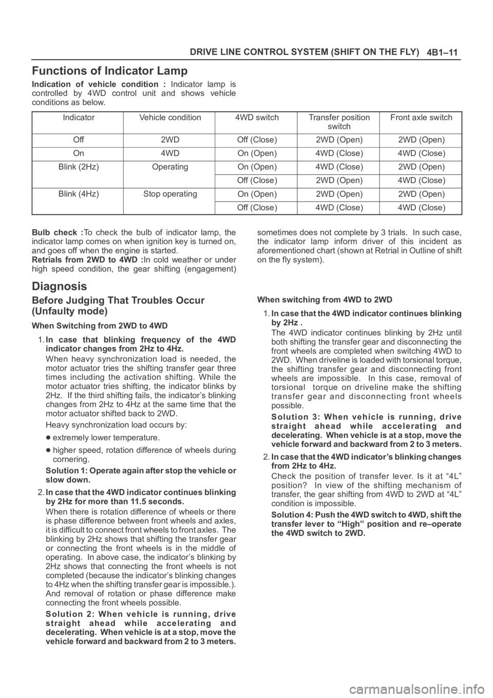
Functions of Indicator Lamp
Indication of vehicle condition : Indicator lamp is
controlled by 4WD control unit and shows vehicle
conditions as below.
Indicator
Vehicle condition4WD switchTransfer position
switchFront axle switch
Off2WDOff (Close)2WD (Open)2WD (Open)
On4WDOn (Open)4WD (Close)4WD (Close)
Blink (2Hz)OperatingOn (Open)4WD (Close)2WD (Open)
Off (Close)2WD (Open)4WD (Close)
Blink (4Hz)Stop operatingOn (Open)2WD (Open)2WD (Open)
Off (Close)4WD (Close)4WD (Close)
Bulb check :To check the bulb of indicator lamp, the
indicator lamp comes on when ignition key is turned on,
and goes off when the engine is started.
Retrials from 2WD to 4WD :In cold weather or under
high speed condition, the gear shifting (engagement)sometimes does not complete by 3 trials. In such case,
the indicator lamp inform driver of this incident as
aforementioned chart (shown at Retrial in Outline of shift
on the fly system).
Diagnosis
Before Judging That Troubles Occur
(Unfaulty mode)
When Switching from 2WD to 4WD
1.In case that blinking frequency of the 4WD
indicator changes from 2Hz to 4Hz.
When heavy synchronization load is needed, the
motor actuator tries the shifting transfer gear three
times including the activation shifting. While the
motor actuator tries shifting, the indicator blinks by
2Hz. If the third shifting fails, the indicator’s blinking
changes from 2Hz to 4Hz at the same time that the
motor actuator shifted back to 2WD.
Heavy synchronization load occurs by:
extremely lower temperature.
higher speed, rotation difference of wheels during
cornering.
Solution 1: Operate again after stop the vehicle or
slow down.
2.In case that the 4WD indicator continues blinking
by 2Hz for more than 11.5 seconds.
When there is rotation difference of wheels or there
is phase difference between front wheels and axles,
it is difficult to connect front wheels to front axles. The
blinking by 2Hz shows that shifting the transfer gear
or connecting the front wheels is in the middle of
operating. In above case, the indicator’s blinking by
2Hz shows that connecting the front wheels is not
completed (because the indicator’s blinking changes
to 4Hz when the shifting transfer gear is impossible.).
And removal of rotation or phase difference make
connecting the front wheels possible.
Solution 2: When vehicle is running, drive
straight ahead while accelerating and
decelerating. When vehicle is at a stop, move the
vehicle forward and backward from 2 to 3 meters.When switching from 4WD to 2WD
1.In case that the 4WD indicator continues blinking
by 2Hz .
The 4WD indicator continues blinking by 2Hz until
both shifting the transfer gear and disconnecting the
front wheels are completed when switching 4WD to
2WD. When driveline is loaded with torsional torque,
the shifting transfer gear and disconnecting front
wheels are impossible. In this case, removal of
torsional torque on driveline make the shifting
transfer gear and disconnecting front wheels
possible.
Solution 3: When vehicle is running, drive
straight ahead while accelerating and
decelerating. When vehicle is at a stop, move the
vehicle forward and backward from 2 to 3 meters.
2.In case that the 4WD indicator’s blinking changes
from 2Hz to 4Hz.
Check the position of transfer lever. Is it at “4L”
position? In view of the shifting mechanism of
transfer, the gear shifting from 4WD to 2WD at “4L”
condition is impossible.
Solution 4: Push the 4WD switch to 4WD, shift the
transfer lever to “High” position and re–operate
the 4WD switch to 2WD.