Page 3722 of 6000
B-18
FL-1 Main
80A
0.5G/R16
107 8
I-32
I-32 C-16
10A0.3R/W
0.5BRBackup
Power supply (12V)
Unit ground
Automatic heater/air conditioner control unit
B-18B-36H-14
C-20
10A A/C
Relay:
Heater and air
conditioner
0.5B
1.25B 2B
Lighting switchLighting switch
H-141H-269
H-2614
H-2720
H-1614 2
14
3 B-36
H-16
H-26H-27I-32
D08RY00175
Page 3777 of 6000
HD6 TYPE COMPRESSOR
Metric Thread Size Information
Compressor to mounting bracket bolts (Front)
M10
1.5 – 6H
Compressor to mounting bracket bolts (Rear)
M8
1.25 – 6H
Suction-discharge port screw
M10
1.5 – 6HCompressor shaft
M9
1.25 – 6H
Internal hub-clutch drive assembly
M22
1.5 – 6H
COMPRESSOR CLUTCH PLATE AND HUB
ASSEMBLY
Removal
1. Clamp the holding fixture J-33026 in a vise and
attach compressor to holding fixture with thumb
screws J-33026-1.
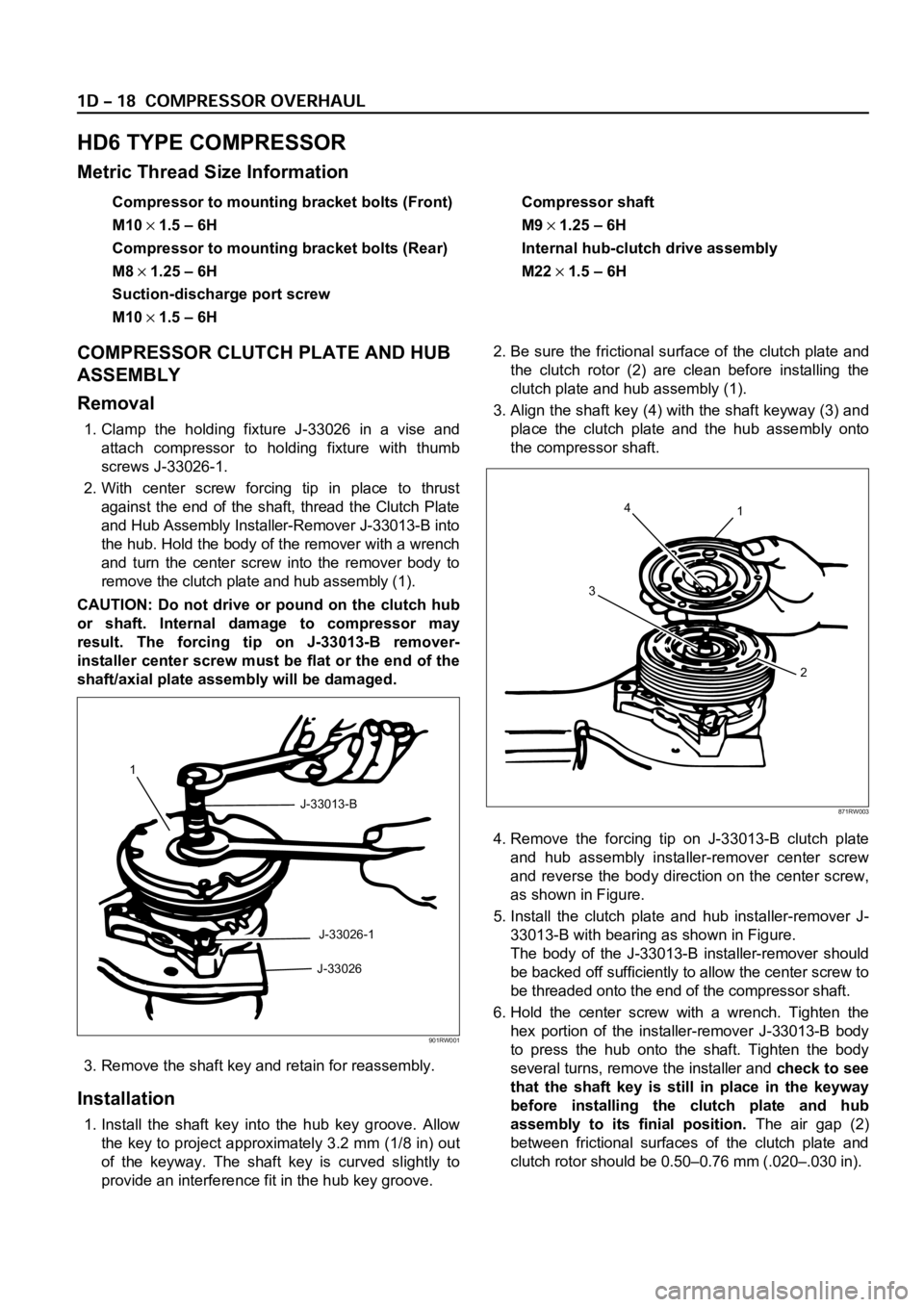
2. With center screw forcing tip in place to thrust
against the end of the shaft, thread the Clutch Plate
and Hub Assembly Installer-Remover J-33013-B into
the hub. Hold the body of the remover with a wrench
and turn the center screw into the remover body to
remove the clutch plate and hub assembly (1).
CAUTION: Do not drive or pound on the clutch hub
or shaft. Internal damage to compressor may
result. The forcing tip on J-33013-B remover-
installer center screw must be flat or the end of the
shaft/axial plate assembly will be damaged.
3. Remove the shaft key and retain for reassembly.
Installation
1. Install the shaft key into the hub key groove. Allow
the key to project approximately 3.2 mm (1/8 in) out
of the keyway. The shaft key is curved slightly to
provide an interference fit in the hub key groove.2. Be sure the frictional surface of the clutch plate and
the clutch rotor (2) are clean before installing the
clutch plate and hub assembly (1).
3. Align the shaft key (4) with the shaft keyway (3) and
place the clutch plate and the hub assembly onto
the compressor shaft.
4. Remove the forcing tip on J-33013-B clutch plate
and hub assembly installer-remover center screw
and reverse the body direction on the center screw,
as shown in Figure.
5. Install the clutch plate and hub installer-remover J-
33013-B with bearing as shown in Figure.
The body of the J-33013-B installer-remover should
be backed off sufficiently to allow the center screw to
be threaded onto the end of the compressor shaft.
6. Hold the center screw with a wrench. Tighten the
hex portion of the installer-remover J-33013-B body
to press the hub onto the shaft. Tighten the body
several turns, remove the installer and check to see
that the shaft key is still in place in the keyway
before installing the clutch plate and hub
assembly to its finial position.The air gap (2)
between frictional surfaces of the clutch plate and
clutch rotor should be 0.50–0.76 mm (.020–.030 in).
1
J-33013-B
J-33026-1
J-33026
901RW001
4
31
2
871RW003
Page 3942 of 6000
DIFFERENTIAL (FRONT) 4A1–2
Front Drive Axle
Diagnosis
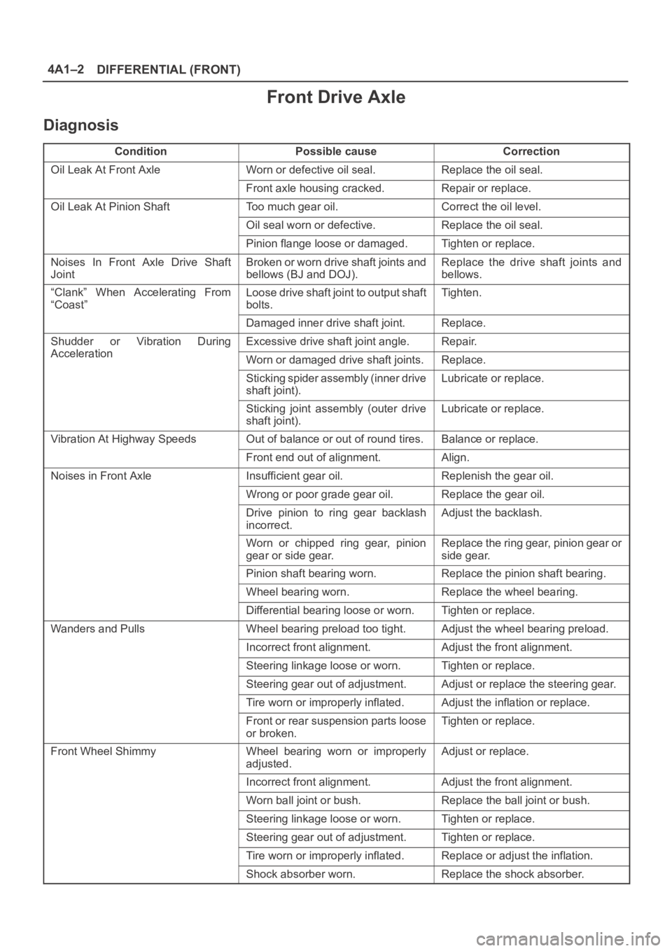
ConditionPossible causeCorrection
Oil Leak At Front AxleWorn or defective oil seal.Replace the oil seal.
Front axle housing cracked.Repair or replace.
Oil Leak At Pinion ShaftToo much gear oil.Correct the oil level.
Oil seal worn or defective.Replace the oil seal.
Pinion flange loose or damaged.Tighten or replace.
Noises In Front Axle Drive Shaft
JointBroken or worn drive shaft joints and
bellows (BJ and DOJ).Replace the drive shaft joints and
bellows.
“Clank” When Accelerating From
“Coast”Loose drive shaft joint to output shaft
bolts.Tighten.
Damaged inner drive shaft joint.Replace.
Shudder or Vibration During
Acceleration
Excessive drive shaft joint angle.Repair.
AccelerationWorn or damaged drive shaft joints.Replace.
Sticking spider assembly (inner drive
shaft joint).Lubricate or replace.
Sticking joint assembly (outer drive
shaft joint).Lubricate or replace.
Vibration At Highway SpeedsOut of balance or out of round tires.Balance or replace.
Front end out of alignment.Align.
Noises in Front AxleInsufficient gear oil.Replenish the gear oil.
Wrong or poor grade gear oil.Replace the gear oil.
Drive pinion to ring gear backlash
incorrect.Adjust the backlash.
Worn or chipped ring gear, pinion
gear or side gear.Replace the ring gear, pinion gear or
side gear.
Pinion shaft bearing worn.Replace the pinion shaft bearing.
Wheel bearing worn.Replace the wheel bearing.
Differential bearing loose or worn.Tighten or replace.
Wanders and PullsWheel bearing preload too tight.Adjust the wheel bearing preload.
Incorrect front alignment.Adjust the front alignment.
Steering linkage loose or worn.Tighten or replace.
Steering gear out of adjustment.Adjust or replace the steering gear.
Tire worn or improperly inflated.Adjust the inflation or replace.
Front or rear suspension parts loose
or broken.Tighten or replace.
Front Wheel ShimmyWheel bearing worn or improperly
adjusted.Adjust or replace.
Incorrect front alignment.Adjust the front alignment.
Worn ball joint or bush.Replace the ball joint or bush.
Steering linkage loose or worn.Tighten or replace.
Steering gear out of adjustment.Tighten or replace.
Tire worn or improperly inflated.Replace or adjust the inflation.
Shock absorber worn.Replace the shock absorber.
Page 3945 of 6000
4A1–5 DIFFERENTIAL (FRONT)
Front Drive Axle Assembly
Front Drive Axle Assembly and Associated Parts
412RY00001
Legend
(1) Mounting Bolt and Nut
(2) Washer and Spacer
(3) Breather Hose
(4) Shift Switch Connector (with Shift on the Fly)
(5) Protector (with Shift on the Fly)(6) Front Axle Case Assembly and Front Drive
Shaft Assembly (LH side)
(7) Hub Assembly (Disc, Back Plate and Knuckle)
(8) Front Drive Shaft Assembly (RH side)
(9) Propeller Shaft
(10) Bolt
Removal
1. Jack up the vehicle and support it using jack stands.
2. Remove the tire and wheel.
Page 3946 of 6000
DIFFERENTIAL (FRONT) 4A1–6
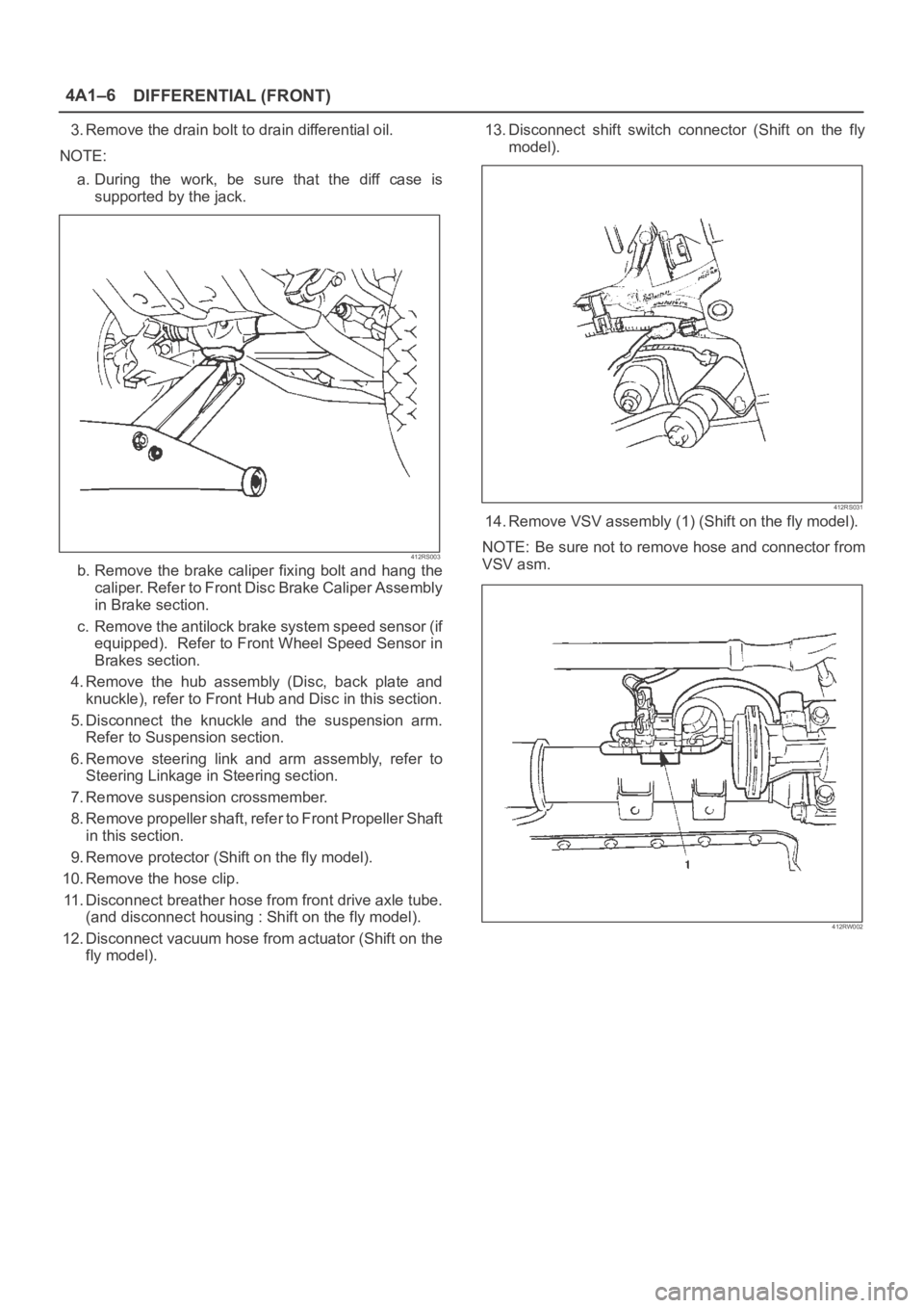
3. Remove the drain bolt to drain differential oil.
NOTE:
a. During the work, be sure that the diff case is
supported by the jack.
412RS003
b. Remove the brake caliper fixing bolt and hang the
caliper. Refer to Front Disc Brake Caliper Assembly
in Brake section.
c. Remove the antilock brake system speed sensor (if
equipped). Refer to Front Wheel Speed Sensor in
Brakes section.
4. Remove the hub assembly (Disc, back plate and
knuckle), refer to Front Hub and Disc in this section.
5. Disconnect the knuckle and the suspension arm.
Refer to Suspension section.
6. Remove steering link and arm assembly, refer to
Steering Linkage in Steering section.
7. Remove suspension crossmember.
8. Remove propeller shaft, refer to Front Propeller Shaft
in this section.
9. Remove protector (Shift on the fly model).
10. Remove the hose clip.
11. Disconnect breather hose from front drive axle tube.
(and disconnect housing : Shift on the fly model).
12. Disconnect vacuum hose from actuator (Shift on the
fly model).13. Disconnect shift switch connector (Shift on the fly
model).
412RS031
14. Remove VSV assembly (1) (Shift on the fly model).
NOTE: Be sure not to remove hose and connector from
VSV asm.
412RW002
Page 3948 of 6000
DIFFERENTIAL (FRONT) 4A1–8
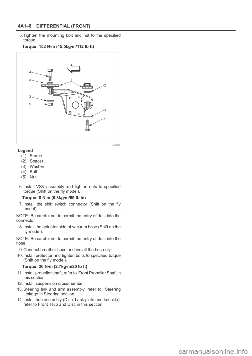
5. Tighten the mounting bolt and nut to the specified
torque.
Torque: 152 Nꞏm (15.5kgꞏm/112 lb ft)
412RW005
Legend
(1) Frame
(2) Spacer
(3) Washer
(4) Bolt
(5) Nut
6. Install VSV assembly and tighten nuts to specified
torque (Shift on the fly model).
Torque: 8 Nꞏm (0.8kgꞏm/69 lb in)
7. Install the shift switch connector (Shift on the fly
model).
NOTE: Be careful not to permit the entry of dust into the
connector.
8. Install the actuator side of vacuum hose (Shift on the
fly model).
NOTE: Be careful not to permit the entry of dust into the
hose.
9. Connect breather hose and install the hose clip.
10. Install protector and tighten bolts to specified torque
(Shift on the fly model).
Torque: 26 Nꞏm (2.7kgꞏm/20 lb ft)
11. Install propeller shaft, refer to Front Propeller Shaft in
this section.
12. Install suspension crossmember.
13. Steering link and arm assembly, refer to Steering
Linkage in Steering section.
14. Install hub assembly (Disc, back plate and knuckle),
refer to Front Hub and Disc in this section.
Page 3953 of 6000
4A1–13 DIFFERENTIAL (FRONT)
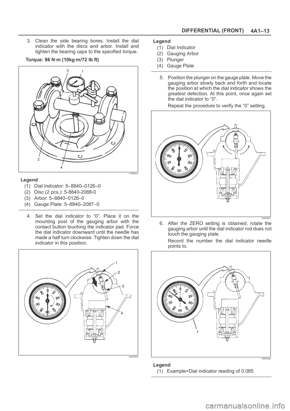
3. Clean the side bearing bores. Install the dial
indicator with the discs and arbor. Install and
tighten the bearing caps to the specified torque.
To r q u e : 9 8 N ꞏm ( 1 0 k g ꞏm / 7 2 l b f t )
415RS010
Legend
(1) Dial Indicator: 5–8840–0126–0
(2) Disc (2 pcs.): 5-8840-2088-0
(3) Arbor: 5–8840–0128–0
(4) Gauge Plate: 5–8840–2087–0
4. Set the dial indicator to “0”. Place it on the
mounting post of the gauging arbor with the
contact button touching the indicator pad. Force
the dial indicator downward until the needle has
made a half turn clockwise. Tighten down the dial
indicator in this position.
425RS020
Legend
(1) Dial Indicator
(2) Gauging Arbor
(3) Plunger
(4) Gauge Plate
5. Position the plunger on the gauge plate. Move the
gauging arbor slowly back and forth and locate
the position at which the dial indicator shows the
greatest defection. At this point, once again set
the dial indicator to “0”.
Repeat the procedure to verify the “0” setting.
425RS021
6. After the ZERO setting is obtained, rotate the
gauging arbor until the dial indicator rod does not
touch the gauging plate.
Record the number the dial indicator needle
points to.
425RS022
Legend
(1) Example=Dial indicator reading of 0.085
Page 3958 of 6000
DIFFERENTIAL (FRONT) 4A1–18
4. Adjust feeler gauge thickness from side to side
until ring gear backlash is in the specified range.
Backlash: 0.13–0.18 mm(0.005 –0.007 in)
425RS032With zero end play and correct backlash estab-
lished, remove the feeler gauge packs, determine
the thickness of the shims required and add 0.05
mm (0.002 in) to each shim pack to provide side
bearing preload. Always use new shims.
5. Use bearing remover 5–8840–0013–0 and
5–8840–0014–0 and pilot 9–8521–1743–0 to
remove side bearing.
415RW020
13. Install the side bearings together with the selected
shims.
425RS029
Legend
(1) Drive Handle:5–8840–0007–0
(2) Installer: 9–8522–1164–0
(3) Pilot: 9–8521–1743–0
14. Install side bearing outer race.
15. Install differential cage assembly.
16. Install bearing cap then align the setting marks(1)
applied at disassembly.
425RS035