Page 3382 of 6000
EXTERIOR/INTERIOR TRIM8J–3
Dash Side Trim Panel
Removal
1. Disconnect the battery ground cable.
2. Remove the Front door sill plate(2).
3. Remove the Dash side trim panel(3).
Turn up the door inner seal(1) of the body panel to
remove the clips of the trim panel.
Take care not to damage the harness and the
controller on the back of the trim panel.
643RW005
Installation
To install, follow the removal steps in the reverse order,
noting the following point.
1. Lap the door inner seal over the trim panel to install
them securely to the body panel.
Assist Grip
Parts Location
745RW006
Legend
(1) Assist Grip
Removal and Installation
Refer to the Consoles removal and installation steps
in this section.
Page 3391 of 6000
8J–12EXTERIOR/INTERIOR TRIM
2. Pass the inside handle through the mounting hole of
the trim panel. Assemble the trim panel. Engage
securely seven clips into the door panel. Also, leave
the connector of the power window drawn out to its
prescribed position, so that it will not caught.
3. Put back the inside handle(3) to the original position
of the link(5). Fit the claw(4) of the inside handle
securely into the hole of the door panel. Fix the
handle with the screw.
632RW011
Page 3417 of 6000

8J–38EXTERIOR/INTERIOR TRIM
Power Door Mirror System
General Description
The circuit consists of the starter switch, door mirror
control switch, folding switch, defogger switch and door
mirrors on both sides.
The door mirror switch consists of the control switch,
folding switch and defogger switch.
When the control switch is operated with the starter
switch at either “ACC” or “ON” position, the motors
incorporated in the door mirrors on both sides rotates to
allow the horizontal and vertical adjustment of mirror
angles.
The folding switch can be used to fold the mirror and
return it to its original position.
When turning on the door mirror defogger switch with the
starter switch at “ON” position, built-in heater in the mirror
is activated to perform the defogger function.
Door Mirror Switch Assembly (Con-
trol Switch, Folding Switch and De-
fogger Switch) Removal
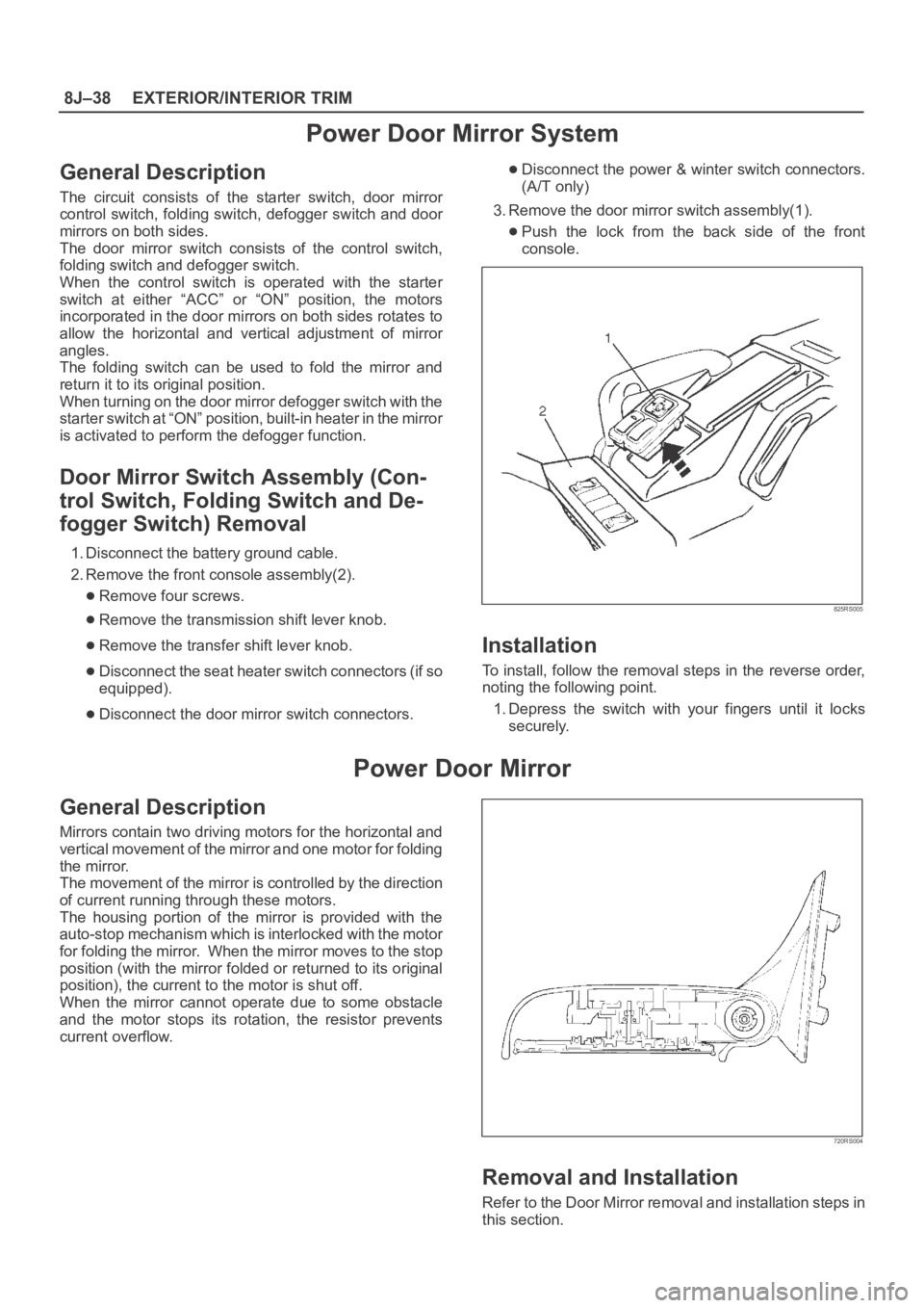
1. Disconnect the battery ground cable.
2. Remove the front console assembly(2).
Remove four screws.
Remove the transmission shift lever knob.
Remove the transfer shift lever knob.
Disconnect the seat heater switch connectors (if so
equipped).
Disconnect the door mirror switch connectors.
Disconnect the power & winter switch connectors.
(A/T only)
3. Remove the door mirror switch assembly(1).
Push the lock from the back side of the front
console.
825RS005
Installation
To install, follow the removal steps in the reverse order,
noting the following point.
1. Depress the switch with your fingers until it locks
securely.
Power Door Mirror
General Description
Mirrors contain two driving motors for the horizontal and
vertical movement of the mirror and one motor for folding
the mirror.
The movement of the mirror is controlled by the direction
of current running through these motors.
The housing portion of the mirror is provided with the
auto-stop mechanism which is interlocked with the motor
for folding the mirror. When the mirror moves to the stop
position (with the mirror folded or returned to its original
position), the current to the motor is shut off.
When the mirror cannot operate due to some obstacle
and the motor stops its rotation, the resistor prevents
current overflow.
720RS004
Removal and Installation
Refer to the Door Mirror removal and installation steps in
this section.
Page 3449 of 6000

SUPPLEMENTAL RESTRAINT SYSTEM 9J–12
Deployed Air Bag Assembly (Driver Side)
“You should wear gloves and glasses. After the air bag
assembly has been deployed, the surface of the air bag
may contain solid particulate. This solid particulate
c o n s i s t s p r i m a r i l y o f b y p r oducts of the chemical reaction,
Potassium Chloride and copper metal dust. Compounds
of Potassium Borate, Strontium Chloride, Copper
Chloride, and Ammonium Chloride may be found in
amounts of about 1% (each) of the total particulate.”
Deployed Pretensioner Seat Belt.
You should wear gloves and safety glasses. After the
pretensioner seat belt has been deployed, the surface of
the pretensioner seat belt cylinder may heating up.
Air Bag Assembly and/or Pretensioner
Seat Belt Scrapping Procedure.
During the cause of vehicle’s useful life, certain situations
may arise which will necessitate the disposal of a live air
bag and/or pretensioner seat belt. (This information
covers proper procedures for disposing of a live air bag
assembly and/or pretensioner seat belt.)
Before a live air bag assembly can be dispose off, it must
be deployed.
A live air bag assembly and/or pretensioner seat belt
must not be disposed of though normal refuse channels.
WARNING: FAILURE TO FOLLOW PROPER
SUPPLEMENTAL RESTRAINT SYSTEM (SRS) AIR
BAG ASSEMBLY DISPOSAL PROCEDURES CAN
RESULT IN AIR BAG DEPLOYMENT WHICH MAY
CAUSE PERSONAL INJURY. AN UNDPLOYED AIR
BAG ASSEMBLY MUST NOT BE DISPOSED OF
THROUGH NORMAL REFUSE CHANNELS. THE
UNDEPLOYED AIR BAG ASSEMBLY CONTAINS
SUBSTANCES THAT CAN CAUSE SEVERE ILLNESS
OR PERSONAL INJURY IF THE SEALED CONTAINER
IS DAMAGED DURING DISPOSAL. DISPOSAL IN
ANY MANNER INCONSISTENT WITH PROPER
PROCEDURES MAY BE A VIOLATION OF LOCAL
LAW.
In situations which require deployment of a live air bag
assembly, deployment may be accomplished inside or
outside the vehicle. The method employed depends
upon the final disposition of the particular vehicle, as
noted in “Deployment Outside Vehicle” and “Deployment
Inside Vehicle” in this section.
Cautions About Air Bag Deployment And
Disposal
Failure to follow proper procedures could result in
erroneous air bag deployment which may cause personal
injury be sure to follow proper procedures.
1. Turn off (Lock) the ignition switch and disconnect the
minus terminal of the battery, then start the work 15 or
more sec later. (Air bag is designed to work by the
back-up power source even if the battery power
source is cut off at vehicle collision).
2. Be sure not to disassemble the air bag.
3. Do not give an impact to the air bag and bring the air
bag close to magnet. (The air bag could deploy
unexpectedly).4. Place the air bag with its trim cover up.
5. Do not let the air bag deploy directly on the floor. (The
air bag may be blown off 2
3 m (6.5 or 10 feet)).
6. Be sure to install the air bag firmly to a deployment
tool (fixing tool).
7. Set a battery 10 m (33 feet) or more away from the air
bag.
8. Before disconnecting air bag harness, ground the
worker by touching the vehicle outer panel with bare
hand.
9. When connecting or disconnecting the harness, do
not work just in front of the air bag.
10. As deployment gives rise to big sound, warn the
people around against it. Further, try to reduce the
sound by covering the steering wheel or tires, and
shut the vehicle windows in case of deployment
inside the vehicle.
11. As deployment generates smoke, select a well
ventilated place. (In case of deployment indoors,
avoid deployment just under a fire alarm, smoke
sensor, and fluorescent lamps).
12. Be careful not to inhale the smoke after deployment.
13. If part of the vehicle glass is damaged, cover the
vehicle with a car cover to prevent the glass from
braking at the time of deployment.
14. Do not touch the air bag immediately after
deployment, since it remains hot for 30 minutes.
15. Do not water the air bag immediately after
deployment.
16. Wear safety glasses and gloves throughout the work
and wash the glasses and gloves after the work.
17. Do not reuse the removed air bag for another vehicle.
(Deployment characteristic is different with vehicle
types).
Deployment Outside Vehicle (Driver Air
Bag Assembly)
Deployment outside the vehicle is proper when the
vehicle is to be returned to service. This includes, for
example, situations in which the vehicle will be returned to
useful service after a functionally or cosmetically deficient
air bag assembly is replaced. Deployment and disposal
of a malfunctioning air bag assembly is, of course, subject
to any required retention period.
For deployment of a live (undeployed) air bag assembly
outside the vehicle, the deployment procedure must be
followed exactly. Always wear safety glasses during this
deployment procedure until a deployed air bag assembly
is scrapped or until an undeployed air bag assembly is
shipped. Before performing the procedures you should
be familiar with servicing the SRS and with proper
handling of the air bag assembly. Procedures should be
read fully before they are performed.
The following procedure requires use of 5–8840–2468–0
SRS deployment harness with appropriate pigtail
adapter. Do not attempt procedure without
5–8840–2468–0 adapter.
WARNING: FAILURE TO FOLLOW PROCEDURES IN
THE ORDER LISTED MAY RESULT IN PERSONAL
INJURY. NEVER CONNECT DEPLOYMENT
Page 3465 of 6000
SUPPLEMENTAL RESTRAINT SYSTEM 9J–28
Tech 2 Scan Tool
From 98 MY, Isuzu dealer service departments are
recommended to use Tech 2. Please refer to Tech 2 scan
tool user guide.
901RW200
Legend
(1) PCMCIA Card
(2) RS 232 Loop Back Connector
(3) SAE 16/19 Adaptor
(4) DLC Cable
(5) Tech–2
Getting Started
Before operating the Isuzu PCMCIA card with the
Tech 2, the following steps must be performed:
1. Insert the Isuzu 98 System PCMCIA card (1) into the
Tech 2 (5).
2. Connect the SAE 16/19 adapter (3) to the DLC cable
(4).3. Connect the DLC cable to the Tech 2 (5)
4. Make sure of the vehicle ignition is off.
5. Connect the Tech 2 SAE 16/19 adapter to the vehicle
ALDL/DLC connector.
060RW220
Legend
(1) For RHD model
(2) For LHD model
6. Turn on the vehicle ignition switch.
7. Verify the Tech 2 power up display.
060RW009
NOTE: The RS232 Loop back connector is only used to
diagnosis Tech 2. Refer to user guide of the Tech 2.
Page 3561 of 6000
PAGE BACK PAGE NEXT
THIS MALUAL INCLUDES THE FOLLOWING SECTIONS:
SECTION No. CONTRNTS
1A HEATING AND VENTILATION
1B AIR CONDITIONING
1D COMPRESSOR OVERHAUL
HOME
1A
1B
1D
Page 3562 of 6000
PAGE BACK PAGE NEXT
THIS MALUAL INCLUDES THE FOLLOWING SECTIONS:
SECTION No. CONTRNTS
00 SERVICE INFORMATION
2A FRONT END ALIGNMENT
HOME
00
2A
Page 3563 of 6000
PAGE BACK PAGE NEXT
THIS MALUAL INCLUDES THE FOLLOWING SECTIONS:
SECTION No. CONTRNTS
3C FRONT SUSPENSION
3D REAR SUSPENSION; COIL SPRING
3E WHEELS AND TIRES
HOME
3C
3D
3E