1998 OPEL FRONTERA service indicator
[x] Cancel search: service indicatorPage 3178 of 6000
METER AND GAUGE8E–1
METER AND GAUGE
CONTENTS
Service Precaution 8E–1. . . . . . . . . . . . . . . . . . . . . .
General Description 8E–1. . . . . . . . . . . . . . . . . . . . .
Meter Assembly 8E–2. . . . . . . . . . . . . . . . . . . . . . . . .
General Description 8E–2. . . . . . . . . . . . . . . . . . . . .
Layout for Meters/Gauges, Warning Lights,
Indicator Lights and Illumination Lights 8E–2. . .
Table for Meter/Gauge Connector Terminal
Connections 8E–8. . . . . . . . . . . . . . . . . . . . . . . . . .
Removal 8E–14. . . . . . . . . . . . . . . . . . . . . . . . . . . . .
Installation 8E–14. . . . . . . . . . . . . . . . . . . . . . . . . . . .
Warning Light Bulb, Indicator Light Bulb,
Illumination Light Bulb, A/T Indicator
Light Bulb 8E–14. . . . . . . . . . . . . . . . . . . . . . . . . . . . . .
Removal 8E–14. . . . . . . . . . . . . . . . . . . . . . . . . . . . .
Installation 8E–14. . . . . . . . . . . . . . . . . . . . . . . . . . . . Vehicle Speed Sensor 8E–15. . . . . . . . . . . . . . . . . . .
Removal 8E–15. . . . . . . . . . . . . . . . . . . . . . . . . . . . .
Installation 8E–15. . . . . . . . . . . . . . . . . . . . . . . . . . . .
Fuel Tank Unit 8E–15. . . . . . . . . . . . . . . . . . . . . . . . . .
Removal 8E–15. . . . . . . . . . . . . . . . . . . . . . . . . . . . .
Installation 8E–15. . . . . . . . . . . . . . . . . . . . . . . . . . . .
Multi Meter 8E–16. . . . . . . . . . . . . . . . . . . . . . . . . . . . .
Removal 8E–16. . . . . . . . . . . . . . . . . . . . . . . . . . . . .
Installation 8E–16. . . . . . . . . . . . . . . . . . . . . . . . . . . .
Ambient Sensor 8E–16. . . . . . . . . . . . . . . . . . . . . . . . .
Removal 8E–16. . . . . . . . . . . . . . . . . . . . . . . . . . . . .
Installation 8E–16. . . . . . . . . . . . . . . . . . . . . . . . . . . .
Main Data and Specifications 8E–17. . . . . . . . . . . . .
Service Precaution
WARNING: IF SO EQUIPPED WITH A
SUPPLEMENTAL RESTRAINT SYSTEM (SRS),
REFER TO THE SRS COMPONENT AND WIRING
LOCATION VIEW IN ORDER TO DETERMINE
WHETHER YOU ARE PERFORMING SERVICE ON OR
NEAR THE SRS COMPONENTS OR THE SRS
WIRING. WHEN YOU ARE PERFORMING SERVICE
ON OR NEAR THE SRS COMPONENTS OR THE SRS
WIRING, REFER TO THE SRS SERVICE
INFORMATION. FAILURE TO FOLLOW WARNINGS
COULD RESULT IN POSSIBLE AIR BAG
DEPLOYMENT, PERSONAL INJURY, OR
OTHERWISE UNNEEDED SRS SYSTEM REPAIRS.
CAUTION: Always use the correct fastener in the
proper location. When you replace a fastener, use
ONLY the exact part number for that application.
ISUZU will call out those fasteners that require a
replacement after removal. ISUZU will also call out
the fasteners that require thread lockers or thread
sealant. UNLESS OTHERWISE SPECIFIED, do not
use supplemental coatings (Paints, greases, or other
corrosion inhibitors) on threaded fasteners or
fastener joint interfaces. Generally, such coatings
adversely affect the fastener torque and the joint
clamping force, and may damage the fastener. When
you install fasteners, use the correct tightening
sequence and specifications. Following these
instructions can help you avoid damage to parts and
systems.
General Description
The circuit consists of the starter switch, meter assembly,
vehicle speed sensor, transmission switch, lighting
switch, turn signal switch, thermo unit, oil pressure unit,
Powertrain Control Module (PCM), fuel tank unit, 4WD
switch, oil pressure switch, parking brake switch, brake
fluid switch, seat belt switch, illumination controller, multi
meter and ambient sensor.
Page 3340 of 6000
SECURITY AND LOCKS8H–1
BODY AND ACCESSORIES
SECURITY AND LOCKS
CONTENTS
Service Precaution 8H–2. . . . . . . . . . . . . . . . . . . . . .
Front Door Lock Assembly 8H–2. . . . . . . . . . . . . . .
Front Door Lock Assembly and
Associated Parts 8H–2. . . . . . . . . . . . . . . . . . . . . .
Removal 8H–2. . . . . . . . . . . . . . . . . . . . . . . . . . . . .
Installation 8H–3. . . . . . . . . . . . . . . . . . . . . . . . . . . .
Front Outside Handle and Door Lock Cylinder 8H–4
Front Outside Handle, Door Lock Cylinder
and Associated Parts 8H–4. . . . . . . . . . . . . . . . . .
Removal 8H–4. . . . . . . . . . . . . . . . . . . . . . . . . . . . .
Installation 8H–5. . . . . . . . . . . . . . . . . . . . . . . . . . . .
Rear Door Lock Assembly 8H–7. . . . . . . . . . . . . . . .
Rear Door Lock Assembly and Associated
Parts 8H–7. . . . . . . . . . . . . . . . . . . . . . . . . . . . . . . .
Removal 8H–7. . . . . . . . . . . . . . . . . . . . . . . . . . . . .
Installation 8H–8. . . . . . . . . . . . . . . . . . . . . . . . . . . .
Rear Outside Handle 8H–9. . . . . . . . . . . . . . . . . . . .
Rear Outside Handle and Associated Parts 8H–9
Removal 8H–9. . . . . . . . . . . . . . . . . . . . . . . . . . . . .
Installation 8H–10. . . . . . . . . . . . . . . . . . . . . . . . . . . .
Rear Door Inside Lock Knob Link 8H–10. . . . . . . . . .
Removal 8H–10. . . . . . . . . . . . . . . . . . . . . . . . . . . . .
Installation 8H–10. . . . . . . . . . . . . . . . . . . . . . . . . . . .
Door Inside Lock Knob 8H–11. . . . . . . . . . . . . . . . . . .
Removal 8H–11. . . . . . . . . . . . . . . . . . . . . . . . . . . . .
Installation 8H–11. . . . . . . . . . . . . . . . . . . . . . . . . . . .
Door Inside Handle 8H–11. . . . . . . . . . . . . . . . . . . . . .
Removal and Installation 8H–11. . . . . . . . . . . . . . .
Tailgate Lock Assembly (LH) 8H–12. . . . . . . . . . . . . .
Tailgate Lock Assembly (LH) and
Associated Parts 8H–12. . . . . . . . . . . . . . . . . . . . . .
Removal 8H–12. . . . . . . . . . . . . . . . . . . . . . . . . . . . .
Installation 8H–13. . . . . . . . . . . . . . . . . . . . . . . . . . . .
Tailgate Lock Assembly (RH) 8H–14. . . . . . . . . . . . .
Tailgate Lock Assembly (RH) and
Associated Parts 8H–14. . . . . . . . . . . . . . . . . . . . . .
Removal 8H–14. . . . . . . . . . . . . . . . . . . . . . . . . . . . .
Installation 8H–15. . . . . . . . . . . . . . . . . . . . . . . . . . . .
Tailgate Inside Lock Knob 8H–15. . . . . . . . . . . . . . . .
Removal 8H–15. . . . . . . . . . . . . . . . . . . . . . . . . . . . . Installation 8H–15. . . . . . . . . . . . . . . . . . . . . . . . . . . .
Tailgate Inside Handle 8H–16. . . . . . . . . . . . . . . . . . .
Parts Location 8H–16. . . . . . . . . . . . . . . . . . . . . . . .
Removal and Installation 8H–16. . . . . . . . . . . . . . .
Tailgate Outside Handle and/or Tailgate
Lock Cylinder 8H–17. . . . . . . . . . . . . . . . . . . . . . . . . .
Tailgate Outside Handle and/or Tailgate
Lock Cylinder and Associated Parts 8H–17. . . . .
Removal 8H–17. . . . . . . . . . . . . . . . . . . . . . . . . . . . .
Installation 8H–18. . . . . . . . . . . . . . . . . . . . . . . . . . . .
Key 8H–19. . . . . . . . . . . . . . . . . . . . . . . . . . . . . . . . . . . .
Key Coding 8H–19. . . . . . . . . . . . . . . . . . . . . . . . . . .
Key Styles 8H–19. . . . . . . . . . . . . . . . . . . . . . . . . . . . . .
Power Door Lock System 8H–20. . . . . . . . . . . . . . . .
General Description 8H–20
. . . . . . . . . . . . . . . . . . . . . .
Front Door Lock Actuator Removal 8H–20. . . . . .
Front Door Lock Actuator Installation 8H–20. . . . .
Rear Door Lock Actuator Removal 8H–20. . . . . . .
Rear Door Lock Actuator Installation 8H–21. . . . .
Tailgate Lock Actuator Removal 8H–21. . . . . . . . .
Tailgate Lock Actuator Installation 8H–21. . . . . . .
Anti-theft System 8H–22. . . . . . . . . . . . . . . . . . . . . . . .
General Description 8H–22. . . . . . . . . . . . . . . . . . . . . .
Anti-theft & Keyless Entry Control Unit
Removal 8H–22. . . . . . . . . . . . . . . . . . . . . . . . . . . . .
Anti-theft & Keyless Entry Control Unit
Installation 8H–22. . . . . . . . . . . . . . . . . . . . . . . . . . .
Anti-theft Indicator Removal 8H–22. . . . . . . . . . . . .
Anti-theft Indicator Installation 8H–23. . . . . . . . . . .
Anti-theft Horn Removal 8H–23. . . . . . . . . . . . . . . .
Anti-Theft Horn Installation 8H–23. . . . . . . . . . . . . .
Engine Hood Switch Removal 8H–23. . . . . . . . . . .
Engine Hood Switch Installation 8H–23. . . . . . . . .
Keyless Entry System 8H–24. . . . . . . . . . . . . . . . . . . .
ID Code Registration 8H–24. . . . . . . . . . . . . . . . . . .
Answer Back (Anti–theft Horn Operation)
Change Mode 8H–26. . . . . . . . . . . . . . . . . . . . . . . .
Anti–theft & Keyless Entry Control
Unit/Transmitter Replacement 8H–27. . . . . . . . . .
Main Data and Specifications 8H–28. . . . . . . . . . . . .
Page 3552 of 6000
10A–1
CRUISE CONTROL SYSTEM
CONTROL SYSTEM
CRUISE CONTROL SYSTEM
CONTENTS
Service Precaution 10A–1. . . . . . . . . . . . . . . . . . . . . .
General Description 10A–1. . . . . . . . . . . . . . . . . . . . .
Diagnosis 10A–2. . . . . . . . . . . . . . . . . . . . . . . . . . . . . .
Brake Switch 10A–2. . . . . . . . . . . . . . . . . . . . . . . . . . .
Removal 10A–2. . . . . . . . . . . . . . . . . . . . . . . . . . . . .
Installation 10A–2. . . . . . . . . . . . . . . . . . . . . . . . . . . .
Adjustment 10A–3. . . . . . . . . . . . . . . . . . . . . . . . . . .
Clutch Switch 10A–3. . . . . . . . . . . . . . . . . . . . . . . . . . .
Removal and Installation 10A–3. . . . . . . . . . . . . . .
Adjustment 10A–3. . . . . . . . . . . . . . . . . . . . . . . . . . .
Starter Switch 10A–4. . . . . . . . . . . . . . . . . . . . . . . . . . .
Removal 10A–4. . . . . . . . . . . . . . . . . . . . . . . . . . . . .
Installation 10A–4. . . . . . . . . . . . . . . . . . . . . . . . . . . .
Cruise Control Main Switch 10A–5. . . . . . . . . . . . . . . Removal 10A–5. . . . . . . . . . . . . . . . . . . . . . . . . . . . .
Installation 10A–5. . . . . . . . . . . . . . . . . . . . . . . . . . . .
Cruise Control Switch (Combination Switch) 10A–5
Removal and Installation 10A–5. . . . . . . . . . . . . . .
Cruise Control Unit 10A–6. . . . . . . . . . . . . . . . . . . . . .
Removal 10A–6. . . . . . . . . . . . . . . . . . . . . . . . . . . . .
Installation 10A–6. . . . . . . . . . . . . . . . . . . . . . . . . . . .
Cruise Actuator 10A–7. . . . . . . . . . . . . . . . . . . . . . . . .
Actuator Cable Diagram (LHD) 10A–7. . . . . . . . . .
Actuator Cable Diagram (RHD) 10A–7. . . . . . . . . .
Removal 10A–8. . . . . . . . . . . . . . . . . . . . . . . . . . . . .
Installation 10A–8. . . . . . . . . . . . . . . . . . . . . . . . . . . .
Mode Switch 10A–8. . . . . . . . . . . . . . . . . . . . . . . . . . . .
Removal and Installation 10A–8. . . . . . . . . . . . . . .
Service Precaution
WARNING: IF SO EQUIPPED WITH A
SUPPLEMENTAL RESTRAINT SYSTEM (SRS),
REFER TO THE SRS COMPONENT AND WIRING
LOCATION VIEW IN ORDER TO DETERMINE
WHETHER YOU ARE PERFORMING SERVICE ON OR
NEAR THE SRS COMPONENTS OR THE SRS
WIRING. WHEN YOU ARE PERFORMING SERVICE
ON OR NEAR THE SRS COMPONENTS OR THE SRS
WIRING, REFER TO THE SRS SERVICE
INFORMATION. FAILURE TO FOLLOW WARNINGS
COULD RESULT IN POSSIBLE AIR BAG
DEPLOYMENT, PERSONAL INJURY, OR
OTHERWISE UNNEEDED SRS SYSTEM REPAIRS.
CAUTION: Always use the correct fastener in the
proper location. When you replace a fastener, use
ONLY the exact part number for that application.
ISUZU will call out those fasteners that require a
replacement after removal. ISUZU will also call out
the fasteners that require thread lockers or thread
sealant. UNLESS OTHERWISE SPECIFIED, do not
use supplemental coatings (Paints, greases, or other
corrosion inhibitors) on threaded fasteners or
fastener joint interfaces. Generally, such coatings
adversely affect the fastener torque and the joint
clamping force, and may damage the fastener. When
you install fasteners, use the correct tightening
sequence and specifications. Following these
instructions can help you avoid damage to parts and
systems.
General Description
The cruise control keeps the vehicle running at a fixed
speed until a signal canceling this fixed speed is received .
When the main switch “AUTO CRUISE” is turned on with
the vehicle in the running mode, the battery voltage is
applied to the control unit. When a signal from the control
switch is input to the control unit while the vehicle is in this
state, the cruise control actuator is activated to operate
the system. Also, while the system is operating, the
“AUTO CRUISE” indicator light in the meter assembly
lights up.
1. SET/COAST Switch Function
1.Set Function: When the SET/COAST switch is
pressed and released with the main switch on, the
speed at which the vehicle is running at that moment
is stored in the memory, and the vehicle automatically
runs at the stored speed.
2.Coast-down Function: When the SET/COAST
switch is kept on while the vehicle in running, the
vehicle decelerates during that time. The speed at
which vehicle is running when the control switch is
turned off is stored in the memory, and the vehicle
automatically returns to the stored speed.
3.Tap-down Function: When the SET/COAST switch
is turned on and off instantaneously while the vehicle
is running, the vehicle decelerates a mile for each
on/off operation. The vehicle speed at which the
vehicle was running when the SET/COAST was
turned off last is stored in the memory, and the vehicle
automatically returns to this stored speed.
Page 4046 of 6000
4B1–1 DRIVE LINE CONTROL SYSTEM (SHIFT ON THE FLY)
DRIVELINE/AXLE
DRIVELINE CONTROL SYSTEM (SHIFT ON THE FLY)
CONTENTS
Service Precaution 4B1–1. . . . . . . . . . . . . . . . . . . . . .
Shift on the Fly System (Lever Type) 4B1–2. . . . . . .
Outline of Shift on the Fly System
(Lever Type) 4B1–2. . . . . . . . . . . . . . . . . . . . . . . . . . .
Shift on the Fly Vacuum Piping and Electric
Equipment (For Lever Control Type) 4B1–3. . . . . .
Vacuum Piping Diagram 4B1–3. . . . . . . . . . . . . . . .
Inspection and Repair 4B1–4. . . . . . . . . . . . . . . . . .
Shift on the Fly System (Push Button Type) 4B1–7.
Outline of Shift on the Fly System
(Push Button Type) 4B1–7. . . . . . . . . . . . . . . . . . . . Functions of Indicator Lamp 4B1–11. . . . . . . . . . . . . . .
Diagnosis 4B1–11. . . . . . . . . . . . . . . . . . . . . . . . . . . . .
Front Axle Diagnosis 4B1–30. . . . . . . . . . . . . . . . . . .
Shift on the Fly Vacuum Piping and Electric
Equipment (For Push Button Type) 4B1–32. . . . . . . .
Vacuum Piping Diagram 4B1–32. . . . . . . . . . . . . . . .
Inspection and Repair 4B1–33. . . . . . . . . . . . . . . . . .
4WD Control Unit (For Push Button Type) 4B1–36. .
4WD Control Unit Associated Parts 4B1–36. . . . . .
Removal 4B1–37. . . . . . . . . . . . . . . . . . . . . . . . . . . . .
Installation 4B1–37. . . . . . . . . . . . . . . . . . . . . . . . . . . .
Service Precaution
WARNING: IF SO EQUIPPED WITH A
SUPPLEMENTAL RESTRAINT SYSTEM (SRS),
REFER TO THE SRS COMPONENT AND WIRING
LOCATION VIEW IN ORDER TO DETERMINE
WHETHER YOU ARE PERFORMING SERVICE ON OR
NEAR THE SRS COMPONENTS OR THE SRS
WIRING. WHEN YOU ARE PERFORMING SERVICE
ON OR NEAR THE SRS COMPONENTS OR THE SRS
WIRING, REFER TO THE SRS SERVICE
INFORMATION. FAILURE TO FOLLOW WARNINGS
COULD RESULT IN POSSIBLE AIR BAG
DEPLOYMENT, PERSONAL INJURY, OR
OTHERWISE UNNEEDED SRS SYSTEM REPAIRS.
CAUTION: Always use the correct fastener in the
proper location. When you replace a fastener, use
ONLY the exact part number for that application.
ISUZU will call out those fasteners that require a
replacement after removal. ISUZU will also call out
the fasteners that require thread lockers or thread
sealant. UNLESS OTHERWISE SPECIFIED, do not
use supplemental coatings (Paints, greases, or other
corrosion inhibitors) on threaded fasteners or
fastener joint interfaces. Generally, such coatings
adversely affect the fastener torque and the joint
clamping force, and may damage the fastener. When
you install fasteners, use the correct tightening
sequence and specifications. Following these
instructions can help you avoid damage to parts and
systems.
Page 4084 of 6000
4B2–1 DRIVE LINE CONTROL SYSTEM (TOD)
DRIVELINE/AXLE
DRIVELINE CONTROL SYSTEM (TOD)
CONTENTS
Service Precaution 4B2–1. . . . . . . . . . . . . . . . . . . . . .
General Description 4B2–2. . . . . . . . . . . . . . . . . . . . .
System Components 4B2–4. . . . . . . . . . . . . . . . . . . .
Parts Location 4B2–4. . . . . . . . . . . . . . . . . . . . . . . .
Functions of Indicator Lamp 4B2–8. . . . . . . . . . . . . .
Diagnosis 4B2–13. . . . . . . . . . . . . . . . . . . . . . . . . . . . . .
Basic Diagnostic Flow Chart 4B2–17. . . . . . . . . . . . . .
Parts Location 4B2–18. . . . . . . . . . . . . . . . . . . . . . . . . .
Circuit Diagram 4B2–22. . . . . . . . . . . . . . . . . . . . . . . . . Connector List 4B2–34. . . . . . . . . . . . . . . . . . . . . . . . . .
Checking Failed Pin 4B2–36. . . . . . . . . . . . . . . . . . . . .
Checking Failed TOD Control Unit Pin 4B2–39. . . . .
Diagnostic Trouble Codes 4B2–43. . . . . . . . . . . . . . . .
Diagnosis from Trouble Codes 4B2–44. . . . . . . . . . . .
Trouble Diagnosis Depending on The Status
of TOD Indicator 4B2–74. . . . . . . . . . . . . . . . . . . . . . . .
Diagnosis from Symptom 4B2–114. . . . . . . . . . . . . . . . .
Service Precaution
WARNING: IF SO EQUIPPED WITH A
SUPPLEMENTAL RESTRAINT SYSTEM (SRS),
REFER TO THE SRS COMPONENT AND WIRING
LOCATION VIEW IN ORDER TO DETERMINE
WHETHER YOU ARE PERFORMING SERVICE ON OR
NEAR THE SRS COMPONENTS OR THE SRS
WIRING. WHEN YOU ARE PERFORMING SERVICE
ON OR NEAR THE SRS COMPONENTS OR THE SRS
WIRING, REFER TO THE SRS SERVICE
INFORMATION. FAILURE TO FOLLOW WARNINGS
COULD RESULT IN POSSIBLE AIR BAG
DEPLOYMENT, PERSONAL INJURY, OR
OTHERWISE UNNEEDED SRS SYSTEM REPAIRS.CAUTION: Always use the correct fastener in the
proper location. When you replace a fastener, use
ONLY the exact part number for that application.
ISUZU will call out those fasteners that require a
replacement after removal. ISUZU will also call out
the fasteners that require thread lockers or thread
sealant. UNLESS OTHERWISE SPECIFIED, do not
use supplemental coatings (Paints, greases, or other
corrosion inhibitors) on threaded fasteners or
fastener joint interfaces. Generally, such coatings
adversely affect the fastener torque and the joint
clamping force, and may damage the fastener. When
you install fasteners, use the correct tightening
sequence and specifications. Following these
instructions can help you avoid damage to parts and
systems.
Page 4621 of 6000
6D1–2
ENGINE ELECTRICAL
Battery
General Description
There are six battery fluid caps on top of the battery.
These are covered by a paper label.
The battery is completely sealed except for the six small
vent holes on the side. These vent holes permit the
escape of small amounts of gas generated by the battery.
This type of battery has the following advantages over
conventional batteries:
1. There is no need to add water during the entire
service life of the battery.
2. The battery protects itself against overcharging.
The battery will refuse to accept an extensive charge.
(A conventional battery will accept an excessive
charge, resulting in gassing and loss of battery fluid.)
3. The battery is much less vulnerable to self discharge
than a conventional type battery.
Diagnosis
1. Visual Inspection
Inspect the battery for obvious physical damage, such as
a cracked or broken case, which would permit electrolyte
loss.
Replace the battery if obvious physical damage is
discovered during inspection.
Check for any other physical damage and correct it as
necessary.
2. Hydrometer Check
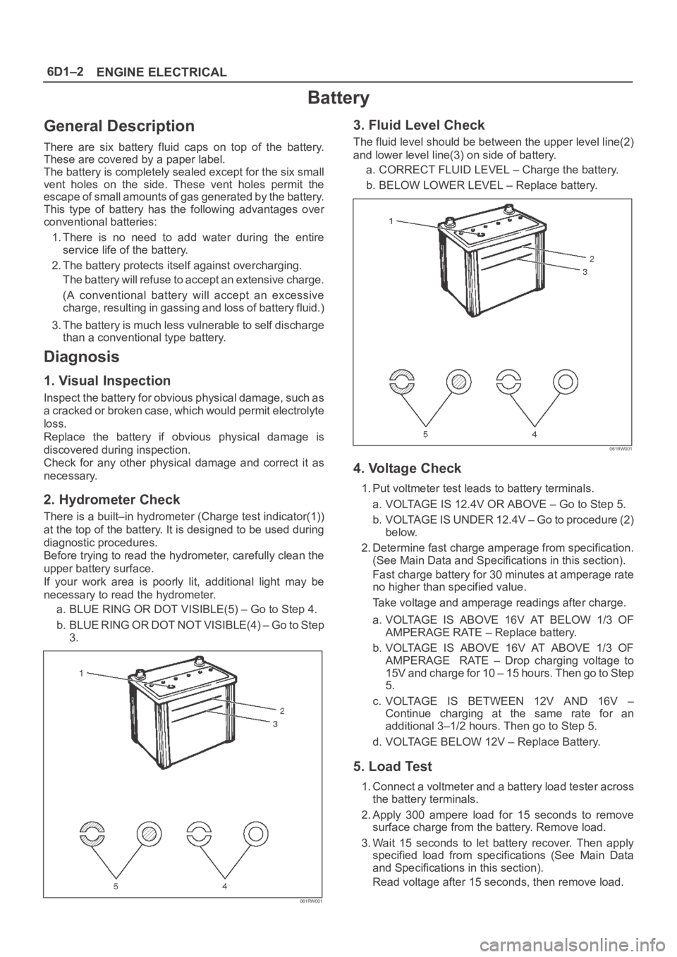
There is a built–in hydrometer (Charge test indicator(1))
at the top of the battery. It is designed to be used during
diagnostic procedures.
Before trying to read the hydrometer, carefully clean the
upper battery surface.
If your work area is poorly lit, additional light may be
necessary to read the hydrometer.
a. BLUE RING OR DOT VISIBLE(5) – Go to Step 4.
b . B L U E R I N G O R D O T N O T V I S I B L E ( 4 ) – G o t o S t e p
3.
061RW001
3. Fluid Level Check
The fluid level should be between the upper level line(2)
and lower level line(3) on side of battery.
a. CORRECT FLUID LEVEL – Charge the battery.
b. BELOW LOWER LEVEL – Replace battery.
061RW001
4. Voltage Check
1. Put voltmeter test leads to battery terminals.
a. VOLTAGE IS 12.4V OR ABOVE – Go to Step 5.
b. VOLTAGE IS UNDER 12.4V – Go to procedure (2)
below.
2. Determine fast charge amperage from specification.
(See Main Data and Specifications in this section).
Fast charge battery for 30 minutes at amperage rate
no higher than specified value.
Take voltage and amperage readings after charge.
a. VOLTAGE IS ABOVE 16V AT BELOW 1/3 OF
AMPERAGE RATE – Replace battery.
b. VOLTAGE IS ABOVE 16V AT ABOVE 1/3 OF
AMPERAGE RATE – Drop charging voltage to
15V and charge for 10 – 15 hours. Then go to Step
5.
c. VOLTAGE IS BETWEEN 12V AND 16V –
Continue charging at the same rate for an
additional 3–1/2 hours. Then go to Step 5.
d. VOLTAGE BELOW 12V – Replace Battery.
5. Load Test
1. Connect a voltmeter and a battery load tester across
the battery terminals.
2. Apply 300 ampere load for 15 seconds to remove
surface charge from the battery. Remove load.
3. Wait 15 seconds to let battery recover. Then apply
specified load from specifications (See Main Data
and Specifications in this section).
Read voltage after 15 seconds, then remove load.
Page 4697 of 6000
6E–40
ENGINE DRIVEABILITY AND EMISSIONS
Common OBD Terms
Diagnostic
When used as a noun, the word diagnostic refers to any
on-board test run by the vehicle’s Diagnostic
Management System. A diagnostic is simply a test run on
a system or component to determine if the system or
component is operating according to specification. There
are many diagnostics, shown in the following list:
Oxygen sensors
Oxygen sensor heaters
EGR
Catalyst monitoring
Enable Criteria
The term “enable criteria” is engineering language for the
conditions necessary for a given diagnostic test to run.
Each diagnostic has a specific list of conditions which
must be met before the diagnostic will run. “Enable
criteria” is another way of saying “conditions required”.
The enable criteria for each diagnostic is listed on the first
page of the DTC description under the heading
“Conditions for Setting the DTC”. Enable criteria varies
with each diagnostic, and typically includes, but is not
limited to the following items:
engine speed
vehicle speed
ECT
MAF/MAP
barometric pressure
IAT
TP
fuel trim
TCC enabled
A/C on
Tr i p
Technically, a trip is a key on-run-key off cycle in which all
the enable criteria for a given diagnostic are met, allowing
the diagnostic to run. Unfortunately, this concept is not
quite that simple. A trip is official when all the enable
criteria for a given diagnostic are met. But because the
enable criteria vary from one diagnostic to another, the
definition of trip varies as well. Some diagnostic are run
when the vehicle is at operating temperature, some when
the vehicle first start up; some require that the vehicle be
cruising at a steady highway speed, some run only when
the vehicle is idle; some diagnostics function with the
TCC disables. Some run only immediately following a
cold engine start-up.
A trip then, is defined as a key on-run-key off cycle in
which the vehicle was operated in such a way as to satisfy
the enables criteria for a given diagnostic, and this
diagnostic will consider this cycle to be one trip. However,
another diagnostic with a different set of enable criteria
(which were not met) during this driving event, would not
consider it a trip. No trip will occur for that particular
diagnostic until the vehicle is driven in such a way as to
meet all the enable criteria.
The Diagnostic Executive
The Diagnostic Executive is a unique segment of
software which is designed to coordinate and prioritize
the diagnostic procedures as well as define the protocol
for recording and displaying their results. The main
responsibilities of the Diagnostic Executive are listed as
following:
Commanding the MIL (“Check Engine” lamp) on and
off
DTC logging and clearing
Freeze Frame data for the first emission related DTC
recorded
Non-emission related Service Lamp (future)
Operating conditions Failure Records buffer, (the
number of records will vary)
Current status information on each diagnostic
The Diagnostic Executive records DTCs and turns on the
MIL when emission-related faults occur. It can also turn
off the MIL if the conditions cease which caused the DTC
to set.
Diagnostic Information
The diagnostic charts and functional checks are designed
to locate a faulty circuit or component through a process
of logical decisions. The charts are prepared with the
requirement that the vehicle functioned correctly at the
time of assembly and that there are not multiple faults
present.
There is a continuous self-diagnosis on certain control
functions. This diagnostic capability is complemented by
the diagnostic procedures contained in this manual. The
language of communicating the source of the malfunction
is a system of diagnostic trouble codes. When a
malfunction is detected by the control module, a
diagnostic trouble code is set and the Malfunction
Indicator Lamp (MIL) (“Check Engine” lamp) is
illuminated.
Malfunction Indicator Lamp (MIL)
The Malfunction Indicator Lamp (MIL) looks the same as
the MIL you are already familiar with (“Check Engine”
lamp). However, OBD requires that the it illuminate under
a strict set of guide lines.
Basically, the MIL is turned on when the PCM detects a
DTC that will impact the vehicle emissions.
The MIL is under the control of the Diagnostic Executive.
The MIL will be turned on if an emissions-related
diagnostic test indicates a malfunction has occurred. It
will stay on until the system or component passes the
same test, for three consecutive trips, with no
emissionsrelated faults.
Extinguishing the MIL
When the MIL is on, the Diagnostic Executive will turn off
the MIL after
three consecutive trips that a “test passed”
has been reported for the diagnostic test that originally
caused the MIL to illuminate.
Although the MIL has been turned off, the DTC will remain
in the PCM memory (both Freeze Frame and Failure
Records) until
forty(40) warm-up cycles after no faults
have been completed.
Page 4699 of 6000
6E–42
ENGINE DRIVEABILITY AND EMISSIONS
Intermittent Malfunction Indicator Lamp
In the case of an “intermittent” fault, the MIL (“Check
Engine” lamp) may illuminate and then (after three trips)
go “OFF”. However, the corresponding diagnostic trouble
code will be stored in the memory. When unexpected
diagnostic trouble codes appear, check for an intermittent
malfunction.
A diagnostic trouble code may reset. Consult the
“Diagnostic Aids” associated with the diagnostic trouble
code. A physical inspection of the applicable sub-system
most often will resolve the problem.
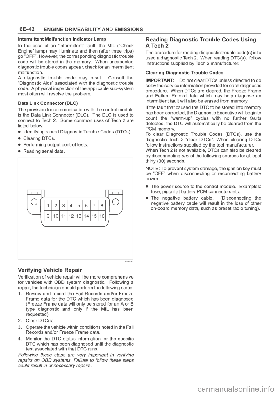
Data Link Connector (DLC)
The provision for communication with the control module
is the Data Link Connector (DLC). The DLC is used to
connect to Tech 2. Some common uses of Tech 2 are
listed below:
Identifying stored Diagnostic Trouble Codes (DTCs).
Clearing DTCs.
Performing output control tests.
Reading serial data.
TS24064
Verifying Vehicle Repair
Verification of vehicle repair will be more comprehensive
for vehicles with OBD system diagnostic. Following a
repair, the technician should perform the following steps:
1. Review and record the Fail Records and/or Freeze
Frame data for the DTC which has been diagnosed
(Freeze Frame data will only be stored for an A or B
type diagnostic and only if the MIL has been
requested).
2. Clear DTC(s).
3. Operate the vehicle within conditions noted in the Fail
Records and/or Freeze Frame data.
4. Monitor the DTC status information for the specific
DTC which has been diagnosed until the diagnostic
test associated with that DTC runs.
Following these steps are very important in verifying
repairs on OBD systems. Failure to follow these steps
could result in unnecessary repairs.
Reading Diagnostic Trouble Codes Using
A Tech 2
The procedure for reading diagnostic trouble code(s) is to
used a diagnostic Tech 2. When reading DTC(s), follow
instructions supplied by Tech 2 manufacturer.
Clearing Diagnostic Trouble Codes
IMPORTANT:Do not clear DTCs unless directed to do
so by the service information provided for each diagnostic
procedure. When DTCs are cleared, the Freeze Frame
and Failure Record data which may help diagnose an
intermittent fault will also be erased from memory.
If the fault that caused the DTC to be stored into memory
has been corrected, the Diagnostic Executive will begin to
count the “warm-up” cycles with no further faults
detected, the DTC will automatically be cleared from the
PCM memory.
To clear Diagnostic Trouble Codes (DTCs), use the
diagnostic Tech 2 “clear DTCs”. When clearing DTCs
follow instructions supplied by the tool manufacturer.
When Tech 2 is not available, DTCs can also be cleared
by disconnecting
one of the following sources for at least
thirty (30) seconds.
NOTE: To prevent system damage, the ignition key must
be “OFF” when disconnecting or reconnecting battery
power.
The power source to the control module. Examples:
fuse, pigtail at battery PCM connectors etc.
The negative battery cable. (Disconnecting the
negative battery cable will result in the loss of other
on-board memory data, such as preset radio tuning).