1998 OPEL FRONTERA service indicator
[x] Cancel search: service indicatorPage 5430 of 6000
6E–1 4JX1–TC ENGINE DRIVEABILITY AND EMISSIONS
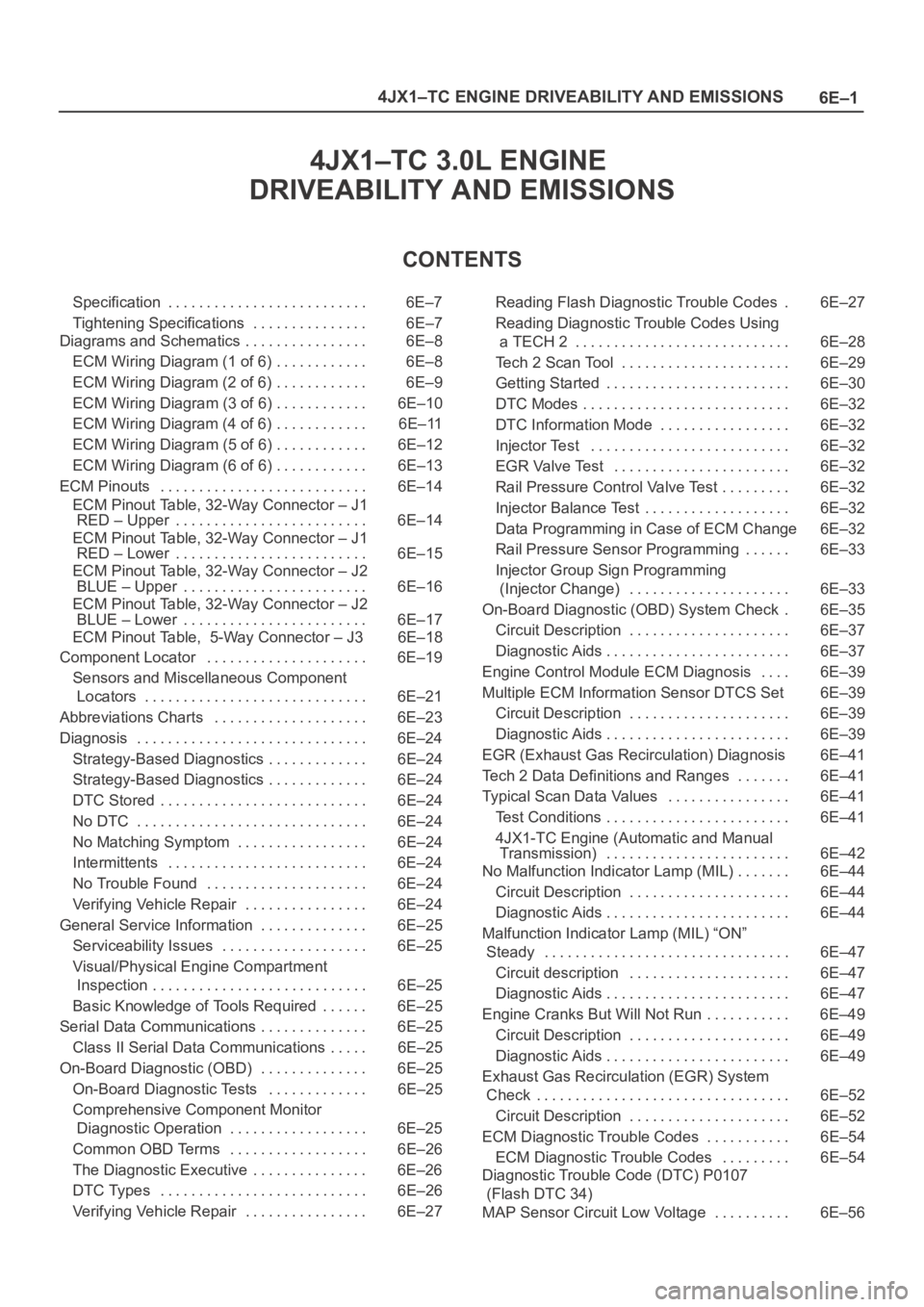
4JX1–TC 3.0L ENGINE
DRIVEABILITY AND EMISSIONS
CONTENTS
Specification 6E–7. . . . . . . . . . . . . . . . . . . . . . . . . .
Tightening Specifications 6E–7. . . . . . . . . . . . . . .
Diagrams and Schematics 6E–8. . . . . . . . . . . . . . . .
ECM Wiring Diagram (1 of 6) 6E–8. . . . . . . . . . . .
ECM Wiring Diagram (2 of 6) 6E–9. . . . . . . . . . . .
ECM Wiring Diagram (3 of 6) 6E–10. . . . . . . . . . . .
ECM Wiring Diagram (4 of 6) 6E–11. . . . . . . . . . . .
ECM Wiring Diagram (5 of 6) 6E–12. . . . . . . . . . . .
ECM Wiring Diagram (6 of 6) 6E–13. . . . . . . . . . . .
ECM Pinouts 6E–14. . . . . . . . . . . . . . . . . . . . . . . . . . .
ECM Pinout Table, 32-Way Connector – J1
RED – Upper 6E–14. . . . . . . . . . . . . . . . . . . . . . . . .
ECM Pinout Table, 32-Way Connector – J1
RED – Lower 6E–15. . . . . . . . . . . . . . . . . . . . . . . . .
ECM Pinout Table, 32-Way Connector – J2
BLUE – Upper 6E–16. . . . . . . . . . . . . . . . . . . . . . . .
ECM Pinout Table, 32-Way Connector – J2
BLUE – Lower 6E–17. . . . . . . . . . . . . . . . . . . . . . . .
ECM Pinout Table, 5-Way Connector – J3 6E–18
Component Locator 6E–19. . . . . . . . . . . . . . . . . . . . .
Sensors and Miscellaneous Component
Locators 6E–21. . . . . . . . . . . . . . . . . . . . . . . . . . . . .
Abbreviations Charts 6E–23. . . . . . . . . . . . . . . . . . . .
Diagnosis 6E–24. . . . . . . . . . . . . . . . . . . . . . . . . . . . . .
Strategy-Based Diagnostics 6E–24. . . . . . . . . . . . .
Strategy-Based Diagnostics 6E–24. . . . . . . . . . . . .
DTC Stored 6E–24. . . . . . . . . . . . . . . . . . . . . . . . . . .
No DTC 6E–24. . . . . . . . . . . . . . . . . . . . . . . . . . . . . .
No Matching Symptom 6E–24. . . . . . . . . . . . . . . . .
Intermittents 6E–24. . . . . . . . . . . . . . . . . . . . . . . . . .
No Trouble Found 6E–24. . . . . . . . . . . . . . . . . . . . .
Verifying Vehicle Repair 6E–24. . . . . . . . . . . . . . . .
General Service Information 6E–25. . . . . . . . . . . . . .
Serviceability Issues 6E–25. . . . . . . . . . . . . . . . . . .
Visual/Physical Engine Compartment
Inspection 6E–25. . . . . . . . . . . . . . . . . . . . . . . . . . . .
Basic Knowledge of Tools Required 6E–25. . . . . .
Serial Data Communications 6E–25. . . . . . . . . . . . . .
Class II Serial Data Communications 6E–25. . . . .
On-Board Diagnostic (OBD) 6E–25. . . . . . . . . . . . . .
On-Board Diagnostic Tests 6E–25. . . . . . . . . . . . .
Comprehensive Component Monitor
Diagnostic Operation 6E–25. . . . . . . . . . . . . . . . . .
Common OBD Terms 6E–26. . . . . . . . . . . . . . . . . .
The Diagnostic Executive 6E–26. . . . . . . . . . . . . . .
DTC Types 6E–26. . . . . . . . . . . . . . . . . . . . . . . . . . .
Verifying Vehicle Repair 6E–27. . . . . . . . . . . . . . . . Reading Flash Diagnostic Trouble Codes 6E–27.
Reading Diagnostic Trouble Codes Using
a TECH 2 6E–28. . . . . . . . . . . . . . . . . . . . . . . . . . . .
Tech 2 Scan Tool 6E–29. . . . . . . . . . . . . . . . . . . . . .
Getting Started 6E–30. . . . . . . . . . . . . . . . . . . . . . . .
DTC Modes 6E–32. . . . . . . . . . . . . . . . . . . . . . . . . . .
DTC Information Mode 6E–32. . . . . . . . . . . . . . . . .
Injector Test 6E–32. . . . . . . . . . . . . . . . . . . . . . . . . .
EGR Valve Test 6E–32. . . . . . . . . . . . . . . . . . . . . . .
Rail Pressure Control Valve Test 6E–32. . . . . . . . .
Injector Balance Test 6E–32. . . . . . . . . . . . . . . . . . .
Data Programming in Case of ECM Change 6E–32
Rail Pressure Sensor Programming 6E–33. . . . . .
Injector Group Sign Programming
(Injector Change) 6E–33. . . . . . . . . . . . . . . . . . . . .
On-Board Diagnostic (OBD) System Check 6E–35.
Circuit Description 6E–37. . . . . . . . . . . . . . . . . . . . .
Diagnostic Aids 6E–37. . . . . . . . . . . . . . . . . . . . . . . .
Engine Control Module ECM Diagnosis 6E–39. . . .
Multiple ECM Information Sensor DTCS Set 6E–39
Circuit Description 6E–39. . . . . . . . . . . . . . . . . . . . .
Diagnostic Aids 6E–39. . . . . . . . . . . . . . . . . . . . . . . .
EGR (Exhaust Gas Recirculation) Diagnosis 6E–41
Tech 2 Data Definitions and Ranges 6E–41. . . . . . .
Typical Scan Data Values 6E–41. . . . . . . . . . . . . . . .
Test Conditions 6E–41. . . . . . . . . . . . . . . . . . . . . . . .
4JX1-TC Engine (Automatic and Manual
Transmission) 6E–42. . . . . . . . . . . . . . . . . . . . . . . .
No Malfunction Indicator Lamp (MIL) 6E–44. . . . . . .
Circuit Description 6E–44. . . . . . . . . . . . . . . . . . . . .
Diagnostic Aids 6E–44. . . . . . . . . . . . . . . . . . . . . . . .
Malfunction Indicator Lamp (MIL) “ON”
Steady 6E–47. . . . . . . . . . . . . . . . . . . . . . . . . . . . . . . .
Circuit description 6E–47. . . . . . . . . . . . . . . . . . . . .
Diagnostic Aids 6E–47. . . . . . . . . . . . . . . . . . . . . . . .
Engine Cranks But Will Not Run 6E–49. . . . . . . . . . .
Circuit Description 6E–49. . . . . . . . . . . . . . . . . . . . .
Diagnostic Aids 6E–49. . . . . . . . . . . . . . . . . . . . . . . .
Exhaust Gas Recirculation (EGR) System
Check 6E–52. . . . . . . . . . . . . . . . . . . . . . . . . . . . . . . . .
Circuit Description 6E–52. . . . . . . . . . . . . . . . . . . . .
ECM Diagnostic Trouble Codes 6E–54. . . . . . . . . . .
ECM Diagnostic Trouble Codes 6E–54. . . . . . . . .
Diagnostic Trouble Code (DTC) P0107
(Flash DTC 34)
MAP Sensor Circuit Low Voltage 6E–56. . . . . . . . . .
Page 5434 of 6000
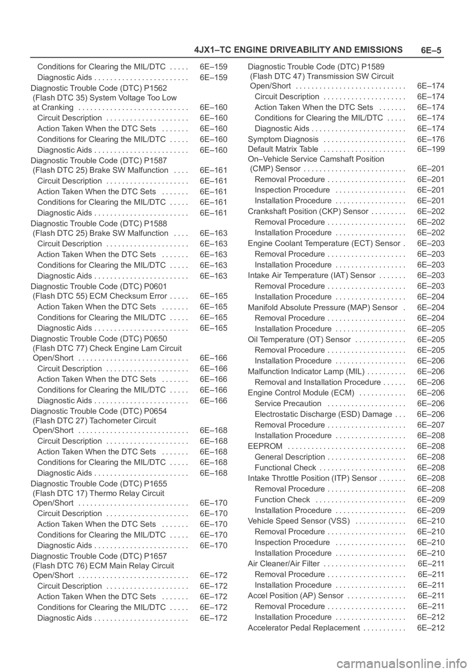
6E–5 4JX1–TC ENGINE DRIVEABILITY AND EMISSIONS
Conditions for Clearing the MIL/DTC 6E–159. . . . .
Diagnostic Aids 6E–159. . . . . . . . . . . . . . . . . . . . . . . .
Diagnostic Trouble Code (DTC) P1562
(Flash DTC 35) System Voltage Too Low
at Cranking 6E–160. . . . . . . . . . . . . . . . . . . . . . . . . . . .
Circuit Description 6E–160. . . . . . . . . . . . . . . . . . . . .
Action Taken When the DTC Sets 6E–160. . . . . . .
Conditions for Clearing the MIL/DTC 6E–160. . . . .
Diagnostic Aids 6E–160. . . . . . . . . . . . . . . . . . . . . . . .
Diagnostic Trouble Code (DTC) P1587
(Flash DTC 25) Brake SW Malfunction 6E–161. . . .
Circuit Description 6E–161. . . . . . . . . . . . . . . . . . . . .
Action Taken When the DTC Sets 6E–161. . . . . . .
Conditions for Clearing the MIL/DTC 6E–161. . . . .
Diagnostic Aids 6E–161. . . . . . . . . . . . . . . . . . . . . . . .
Diagnostic Trouble Code (DTC) P1588
(Flash DTC 25) Brake SW Malfunction 6E–163. . . .
Circuit Description 6E–163. . . . . . . . . . . . . . . . . . . . .
Action Taken When the DTC Sets 6E–163. . . . . . .
Conditions for Clearing the MIL/DTC 6E–163. . . . .
Diagnostic Aids 6E–163. . . . . . . . . . . . . . . . . . . . . . . .
Diagnostic Trouble Code (DTC) P0601
(Flash DTC 55) ECM Checksum Error 6E–165. . . . .
Action Taken When the DTC Sets 6E–165. . . . . . .
Conditions for Clearing the MIL/DTC 6E–165. . . . .
Diagnostic Aids 6E–165. . . . . . . . . . . . . . . . . . . . . . . .
Diagnostic Trouble Code (DTC) P0650
(Flash DTC 77) Check Engine Lam Circuit
Open/Short 6E–166. . . . . . . . . . . . . . . . . . . . . . . . . . . .
Circuit Description 6E–166. . . . . . . . . . . . . . . . . . . . .
Action Taken When the DTC Sets 6E–166. . . . . . .
Conditions for Clearing the MIL/DTC 6E–166. . . . .
Diagnostic Aids 6E–166. . . . . . . . . . . . . . . . . . . . . . . .
Diagnostic Trouble Code (DTC) P0654
(Flash DTC 27) Tachometer Circuit
Open/Short 6E–168. . . . . . . . . . . . . . . . . . . . . . . . . . . .
Circuit Description 6E–168. . . . . . . . . . . . . . . . . . . . .
Action Taken When the DTC Sets 6E–168. . . . . . .
Conditions for Clearing the MIL/DTC 6E–168. . . . .
Diagnostic Aids 6E–168. . . . . . . . . . . . . . . . . . . . . . . .
Diagnostic Trouble Code (DTC) P1655
(Flash DTC 17) Thermo Relay Circuit
Open/Short 6E–170. . . . . . . . . . . . . . . . . . . . . . . . . . . .
Circuit Description 6E–170. . . . . . . . . . . . . . . . . . . . .
Action Taken When the DTC Sets 6E–170. . . . . . .
Conditions for Clearing the MIL/DTC 6E–170. . . . .
Diagnostic Aids 6E–170. . . . . . . . . . . . . . . . . . . . . . . .
Diagnostic Trouble Code (DTC) P1657
(Flash DTC 76) ECM Main Relay Circuit
Open/Short 6E–172. . . . . . . . . . . . . . . . . . . . . . . . . . . .
Circuit Description 6E–172. . . . . . . . . . . . . . . . . . . . .
Action Taken When the DTC Sets 6E–172. . . . . . .
Conditions for Clearing the MIL/DTC 6E–172. . . . .
Diagnostic Aids 6E–172. . . . . . . . . . . . . . . . . . . . . . . . Diagnostic Trouble Code (DTC) P1589
(Flash DTC 47) Transmission SW Circuit
Open/Short 6E–174. . . . . . . . . . . . . . . . . . . . . . . . . . . .
Circuit Description 6E–174. . . . . . . . . . . . . . . . . . . . .
Action Taken When the DTC Sets 6E–174. . . . . . .
Conditions for Clearing the MIL/DTC 6E–174. . . . .
Diagnostic Aids 6E–174. . . . . . . . . . . . . . . . . . . . . . . .
Symptom Diagnosis 6E–176. . . . . . . . . . . . . . . . . . . . .
Default Matrix Table 6E–199. . . . . . . . . . . . . . . . . . . . .
On–Vehicle Service Camshaft Position
(CMP) Sensor 6E–201. . . . . . . . . . . . . . . . . . . . . . . . . .
Removal Procedure 6E–201. . . . . . . . . . . . . . . . . . . .
Inspection Procedure 6E–201. . . . . . . . . . . . . . . . . .
Installation Procedure 6E–201. . . . . . . . . . . . . . . . . .
Crankshaft Position (CKP) Sensor 6E–202. . . . . . . . .
Removal Procedure 6E–202. . . . . . . . . . . . . . . . . . . .
Installation Procedure 6E–202. . . . . . . . . . . . . . . . . .
Engine Coolant Temperature (ECT) Sensor 6E–203.
Removal Procedure 6E–203. . . . . . . . . . . . . . . . . . . .
Installation Procedure 6E–203. . . . . . . . . . . . . . . . . .
Intake Air Temperature (IAT) Sensor 6E–203. . . . . . .
Removal Procedure 6E–203. . . . . . . . . . . . . . . . . . . .
Installation Procedure 6E–204. . . . . . . . . . . . . . . . . .
Manifold Absolute Pressure (MAP) Sensor 6E–204.
Removal Procedure 6E–204. . . . . . . . . . . . . . . . . . . .
Installation Procedure 6E–205. . . . . . . . . . . . . . . . . .
Oil Temperature (OT) Sensor 6E–205. . . . . . . . . . . . .
Removal Procedure 6E–205. . . . . . . . . . . . . . . . . . . .
Installation Procedure 6E–206. . . . . . . . . . . . . . . . . .
Malfunction Indicator Lamp (MIL) 6E–206. . . . . . . . . .
Removal and Installation Procedure 6E–206. . . . . .
Engine Control Module (ECM) 6E–206. . . . . . . . . . . .
Service Precaution 6E–206. . . . . . . . . . . . . . . . . . . .
Electrostatic Discharge (ESD) Damage 6E–206. . .
Removal Procedure 6E–207. . . . . . . . . . . . . . . . . . . .
Installation Procedure 6E–208. . . . . . . . . . . . . . . . . .
EEPROM 6E–208. . . . . . . . . . . . . . . . . . . . . . . . . . . . . .
General Description 6E–208. . . . . . . . . . . . . . . . . . . .
Functional Check 6E–208. . . . . . . . . . . . . . . . . . . . . .
Intake Throttle Position (ITP) Sensor 6E–208. . . . . . .
Removal Procedure 6E–208. . . . . . . . . . . . . . . . . . . .
Function Check 6E–209. . . . . . . . . . . . . . . . . . . . . . .
Installation Procedure 6E–209. . . . . . . . . . . . . . . . . .
Vehicle Speed Sensor (VSS) 6E–210. . . . . . . . . . . . .
Removal Procedure 6E–210. . . . . . . . . . . . . . . . . . . .
Inspection Procedure 6E–210. . . . . . . . . . . . . . . . . .
Installation Procedure 6E–210. . . . . . . . . . . . . . . . . .
Air Cleaner/Air Filter 6E–211. . . . . . . . . . . . . . . . . . . . .
Removal Procedure 6E–211. . . . . . . . . . . . . . . . . . . .
Installation Procedure 6E–211. . . . . . . . . . . . . . . . . .
Accel Position (AP) Sensor 6E–211. . . . . . . . . . . . . . .
Removal Procedure 6E–211. . . . . . . . . . . . . . . . . . . .
Installation Procedure 6E–212. . . . . . . . . . . . . . . . . .
Accelerator Pedal Replacement 6E–212. . . . . . . . . . .
Page 5470 of 6000
6E–41 4JX1–TC ENGINE DRIVEABILITY AND EMISSIONS
EGR (Exhaust Gas Recirculation)
Diagnosis
A diagnosis of the EGR system is covered by DTC
P1403.
EGR VSV circuit diagnosis is covered by DTC P1404.
EGR pressure sensor diagnosis is covered by DTC
P405 and/or P406.
EGR EVRV circuit diagnosis is covered by DTC
P1405. Refer to the DTC charts.
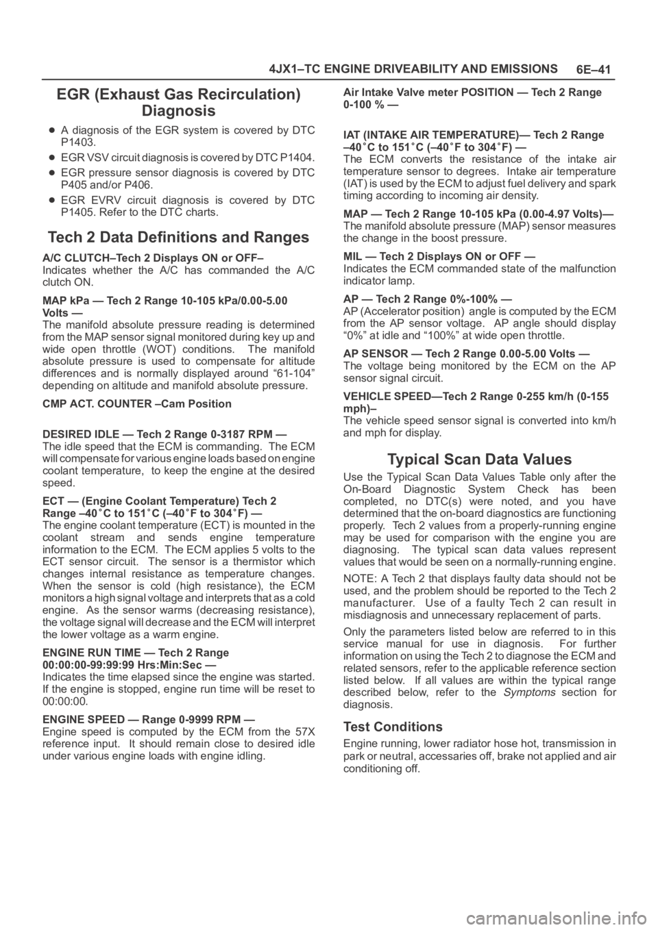
Tech 2 Data Definitions and Ranges
A/C CLUTCH–Tech 2 Displays ON or OFF–
Indicates whether the A/C has commanded the A/C
clutch ON.
MAP kPa — Tech 2 Range 10-105 kPa/0.00-5.00
Vo l t s —
The manifold absolute pressure reading is determined
from the MAP sensor signal monitored during key up and
wide open throttle (WOT) conditions. The manifold
absolute pressure is used to compensate for altitude
differences and is normally displayed around “61-104”
depending on altitude and manifold absolute pressure.
CMP ACT. COUNTER –Cam Position
DESIRED IDLE — Tech 2 Range 0-3187 RPM —
The idle speed that the ECM is commanding. The ECM
will compensate for various engine loads based on engine
coolant temperature, to keep the engine at the desired
speed.
ECT — (Engine Coolant Temperature) Tech 2
Range –40
C to 151C (–40F to 304F) —
The engine coolant temperature (ECT) is mounted in the
coolant stream and sends engine temperature
information to the ECM. The ECM applies 5 volts to the
ECT sensor circuit. The sensor is a thermistor which
changes internal resistance as temperature changes.
When the sensor is cold (high resistance), the ECM
monitors a high signal voltage and interprets that as a cold
engine. As the sensor warms (decreasing resistance),
the voltage signal will decrease and the ECM will interpret
the lower voltage as a warm engine.
ENGINE RUN TIME — Tech 2 Range
00:00:00-99:99:99 Hrs:Min:Sec —
Indicates the time elapsed since the engine was started.
If the engine is stopped, engine run time will be reset to
00:00:00.
ENGINE SPEED — Range 0-9999 RPM —
Engine speed is computed by the ECM from the 57X
reference input. It should remain close to desired idle
under various engine loads with engine idling.Air Intake Valve meter POSITION — Tech 2 Range
0-100 % —
IAT (INTAKE AIR TEMPERATURE)— Tech 2 Range
–40
C to 151C (–40F to 304F) —
The ECM converts the resistance of the intake air
temperature sensor to degrees. Intake air temperature
(IAT) is used by the ECM to adjust fuel delivery and spark
timing according to incoming air density.
MAP — Tech 2 Range 10-105 kPa (0.00-4.97 Volts)—
The manifold absolute pressure (MAP) sensor measures
the change in the boost pressure.
MIL — Tech 2 Displays ON or OFF —
Indicates the ECM commanded state of the malfunction
indicator lamp.
AP — Tech 2 Range 0%-100% —
AP (Accelerator position) angle is computed by the ECM
from the AP sensor voltage. AP angle should display
“0%” at idle and “100%” at wide open throttle.
AP SENSOR — Tech 2 Range 0.00-5.00 Volts —
The voltage being monitored by the ECM on the AP
sensor signal circuit.
VEHICLE SPEED—Tech 2 Range 0-255 km/h (0-155
mph)–
The vehicle speed sensor signal is converted into km/h
and mph for display.
Typical Scan Data Values
Use the Typical Scan Data Values Table only after the
On-Board Diagnostic System Check has been
completed, no DTC(s) were noted, and you have
determined that the on-board diagnostics are functioning
properly. Tech 2 values from a properly-running engine
may be used for comparison with the engine you are
diagnosing. The typical scan data values represent
values that would be seen on a normally-running engine.
NOTE: A Tech 2 that displays faulty data should not be
used, and the problem should be reported to the Tech 2
manufacturer. Use of a faulty Tech 2 can result in
misdiagnosis and unnecessary replacement of parts.
Only the parameters listed below are referred to in this
service manual for use in diagnosis. For further
information on using the Tech 2 to diagnose the ECM and
related sensors, refer to the applicable reference section
listed below. If all values are within the typical range
described below, refer to the
Symptoms section for
diagnosis.
Test Conditions
Engine running, lower radiator hose hot, transmission in
park or neutral, accessaries off, brake not applied and air
conditioning off.
Page 5477 of 6000
6E–48
4JX1–TC ENGINE DRIVEABILITY AND EMISSIONS
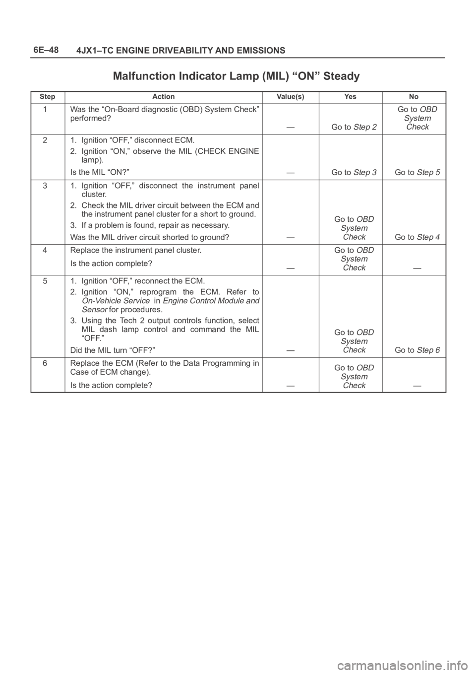
Malfunction Indicator Lamp (MIL) “ON” Steady
StepActionVa l u e ( s )Ye sNo
1Was the “On-Board diagnostic (OBD) System Check”
performed?
—Go to Step 2
Go to OBD
System
Check
21. Ignition “OFF,” disconnect ECM.
2. Ignition “ON,” observe the MIL (CHECK ENGINE
lamp).
Is the MIL “ON?”
—Go to Step 3Go to Step 5
31. Ignition “OFF,” disconnect the instrument panel
cluster.
2. Check the MIL driver circuit between the ECM and
the instrument panel cluster for a short to ground.
3. If a problem is found, repair as necessary.
Was the MIL driver circuit shorted to ground?
—
Go to OBD
System
Check
Go to Step 4
4Replace the instrument panel cluster.
Is the action complete?
—
Go to OBD
System
Check
—
51. Ignition “OFF,” reconnect the ECM.
2. Ignition “ON,” reprogram the ECM. Refer to
On-Vehicle Service in Engine Control Module and
Sensor
for procedures.
3. Using the Tech 2 output controls function, select
MIL dash lamp control and command the MIL
“OFF.”
Did the MIL turn “OFF?”
—
Go to OBD
System
Check
Go to Step 6
6Replace the ECM (Refer to the Data Programming in
Case of ECM change).
Is the action complete?
—
Go to OBD
System
Check
—
Page 5635 of 6000
6E–206
4JX1–TC ENGINE DRIVEABILITY AND EMISSIONS
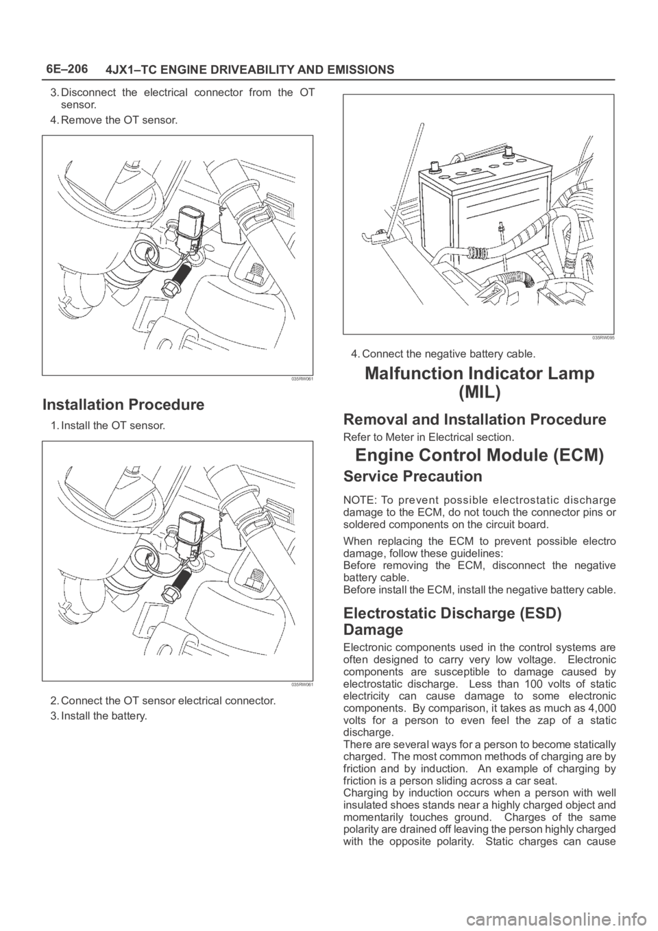
3. Disconnect the electrical connector from the OT
sensor.
4. Remove the OT sensor.
035RW061
Installation Procedure
1. Install the OT sensor.
035RW061
2. Connect the OT sensor electrical connector.
3. Install the battery.
035RW095
4. Connect the negative battery cable.
Malfunction Indicator Lamp
(MIL)
Removal and Installation Procedure
Refer to Meter in Electrical section.
Engine Control Module (ECM)
Service Precaution
NOTE: To prevent possible electrostatic discharge
damage to the ECM, do not touch the connector pins or
soldered components on the circuit board.
When replacing the ECM to prevent possible electro
damage, follow these guidelines:
Before removing the ECM, disconnect the negative
battery cable.
Before install the ECM, install the negative battery cable.
Electrostatic Discharge (ESD)
Damage
Electronic components used in the control systems are
often designed to carry very low voltage. Electronic
components are susceptible to damage caused by
electrostatic discharge. Less than 100 volts of static
electricity can cause damage to some electronic
components. By comparison, it takes as much as 4,000
volts for a person to even feel the zap of a static
discharge.
There are several ways for a person to become statically
charged. The most common methods of charging are by
friction and by induction. An example of charging by
friction is a person sliding across a car seat.
Charging by induction occurs when a person with well
insulated shoes stands near a highly charged object and
momentarily touches ground. Charges of the same
polarity are drained off leaving the person highly charged
with the opposite polarity. Static charges can cause
Page 5656 of 6000
6E–227 4JX1–TC ENGINE DRIVEABILITY AND EMISSIONS
QOS
Diagnostics
– Malfunction Indicator Lamp (Service Engine
Soon lamp)
– Data Link Connector (DLC)
– Data Output
ECM Service Precautions
The ECM is designed to withstand normal current draws
associated with vehicle operation. Avoid overloading any
circuit. When testing for opens and shorts, do not ground
or apply voltage to any of the ECM’s circuits unless
instructed to do so. These circuits should only be tested
using digital voltmeter. The ECM should remain
connected to the ECM or to a recommended breakout
box.
Intake Throttle Position (ITP) Sensor
ITP sensor is a potentiometer type and installed to the
intake throttle valve body. A voltage of 5V is applied
constantly from ECM to ITP sensor thereby to determine
by change in voltage the opening of the intake throttle
valve during warming up.
Transmission Range Switch
IMPORTANT:The vehicle should not be driven with the
transmission range switch disconnected; idle quality will
be affected.
The four inputs from the transmission range switch
indicate to the ECM which position is selected by the
transmission selector lever.
For more information on the transmission on the
transmission range switch, refer to
Automatic
Tr a n s m i s s i o n
.
Accelerator Position Sensor (AP)
AP sensor is a potentiometer type and installed to
accelerator pedal bracket. A voltage of 5V constantly
applied from ECM to the sensor thereby to determine the
accelerator pedaling angle by change in voltage. Further,
this sensor is provided with an accelerator switch, which
is set off only when the accelerator pedal is stepped on.
Aftermarket Electrical and Vacuum
Equipment
Aftermarket (add-on) electrical and vacuum equipment is
defined as any equipment which connects to the vehicle’s
electrical or vacuum systems that is installed on a vehicle
after it leaves the factory. No allowances have been
made in the vehicle design for this type of equipment.
NOTE: No add-on vacuum equipment should be added
to this vehicle.
NOTE: Add-on electrical equipment must only be
connected to the vehicle’s electrical system at the battery
(power and ground).
Add-on electrical equipment, even when installed to
these guidelines, may still cause the powertrain system to
malfunction. This may also include equipment not
connected to the vehicle electrical system such asportable telephones and radios. Therefore, the first step
in diagnosing any powertrain problem is to eliminate all
aftermarket electrical equipment from the vehicle. After
this is done, if the problem still exists, it may be diagnosed
in the normal manner.
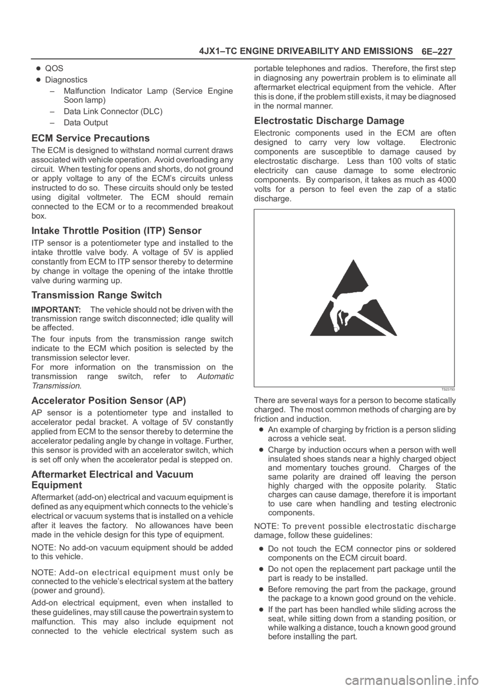
Electrostatic Discharge Damage
Electronic components used in the ECM are often
designed to carry very low voltage. Electronic
components are susceptible to damage caused by
electrostatic discharge. Less than 100 volts of static
electricity can cause damage to some electronic
components. By comparison, it takes as much as 4000
volts for a person to feel even the zap of a static
discharge.
TS23793
There are several ways for a person to become statically
charged. The most common methods of charging are by
friction and induction.
An example of charging by friction is a person sliding
across a vehicle seat.
Charge by induction occurs when a person with well
insulated shoes stands near a highly charged object
and momentary touches ground. Charges of the
same polarity are drained off leaving the person
highly charged with the opposite polarity. Static
charges can cause damage, therefore it is important
to use care when handling and testing electronic
components.
NOTE: To prevent possible electrostatic discharge
damage, follow these guidelines:
Do not touch the ECM connector pins or soldered
components on the ECM circuit board.
Do not open the replacement part package until the
part is ready to be installed.
Before removing the part from the package, ground
the package to a known good ground on the vehicle.
If the part has been handled while sliding across the
seat, while sitting down from a standing position, or
while walking a distance, touch a known good ground
before installing the part.
Page 5682 of 6000
INDUCTION 6J – 5
INSPECTION AND REPAIR
Make the necessary adjustments, repairs and part
replacements if excessive wear or damage is
discovered during inspection.
Minor servicing operations are described in this section.
Contact the nearest IHI SERVICE FACILITY for major
repairs and maintenance.
Refer to IHI SERVICE NETWORK at the end of this
section for the location of your area’s IHI SERVICE
FACILITY.
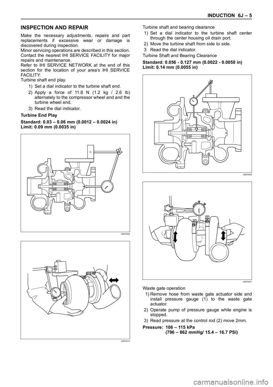
Turbine shaft end play.
1) Set a dial indicator to the turbine shaft end.
2) Apply a force of 11.8 N (1.2 kg / 2.6 lb)
alternately to the compressor wheel and and the
turbine wheel end.
3) Read the dial indicator.
Turbine End Play
Standard: 0.03 – 0.06 mm (0.0012 – 0.0024 in)
Limit: 0.09 mm (0.0035 in)Turbine shaft and bearing clearance
1) Set a dial indicator to the turbine shaft center
through the center housing oil drain port.
2) Move the turbine shaft from side to side.
3 Read the dial indicator.
Turbine Shaft and Bearing Clearance
Standard: 0.056 - 0.127 mm (0.0022 - 0.0050 in)
Limit: 0.14 mm (0.0055 in)
Waste gate operation
1) Remove hose from waste gate actuator side and
install pressure gauge (1) to the waste gate
actuator.
2) Operate pump of pressure gauge while engine is
stopped.
3) Read pressure at the control rod (2) move 2mm.
Pressure: 106 – 115 kPa
(796 – 862 mmHg/ 15.4 – 16.7 PSi)
036RW008
036RW010
036RW009
036RW007
Page 5690 of 6000
7A–1 AUTOMATIC TRANSMISSION (4L30–E)
TRANSMISSION
AUTOMATIC TRANSMISSION (4L30–E)
CONTENTS
Service Precaution 7A–3. . . . . . . . . . . . . . . . . . . . . .
Construction 7A–3. . . . . . . . . . . . . . . . . . . . . . . . . . . .
Range Reference Chart 7A–4. . . . . . . . . . . . . . . . . .
Normal Operation Of 2000 4L30–E
Transmission 7A–5. . . . . . . . . . . . . . . . . . . . . . . . . . .
Diagnosis 7A–5. . . . . . . . . . . . . . . . . . . . . . . . . . . . . .
Driver Information 7A–5. . . . . . . . . . . . . . . . . . . . . . .
General Diagnosis Procedure 7A–8. . . . . . . . . . . . .
Preliminary Inspection Chart 7A–9. . . . . . . . . . . . . .
Checking Transmission Fluid Level and
Condition 7A–10. . . . . . . . . . . . . . . . . . . . . . . . . . . . . .
Test Driving 7A–11. . . . . . . . . . . . . . . . . . . . . . . . . . . . .
Mechanical / Hydraulic Diagnosis Check Trans
Indicator Chart 7A–12. . . . . . . . . . . . . . . . . . . . . . . . . .
Mechanical / Hydraulic Diagnosis
Symptoms Index 7A–13. . . . . . . . . . . . . . . . . . . . . . . .
Stall Test 7A–23. . . . . . . . . . . . . . . . . . . . . . . . . . . . . . .
Line Pressure Test 7A–23. . . . . . . . . . . . . . . . . . . . . .
Shift Speed Chart (V6 3.2L 6VD1 Model) 7A–24. . .
Shift Speed Chart (V6 3.5L 6VE1 Model) 7A–26. .
Lockup Speed Chart (V6 3.2L 6VD1 Model) 7A–28
Lockup Speed Chart (V6 3.5L 6VE1 Model) 7A–28
Changing Transmission Fluid 7A–29. . . . . . . . . . . . .
Selector Lever 7A–29. . . . . . . . . . . . . . . . . . . . . . . . . .
Inspection 7A–29. . . . . . . . . . . . . . . . . . . . . . . . . . . .
Removal 7A–30. . . . . . . . . . . . . . . . . . . . . . . . . . . . .
Installation 7A–30. . . . . . . . . . . . . . . . . . . . . . . . . . . .
Mode Switch 7A–31. . . . . . . . . . . . . . . . . . . . . . . . . . . .
Removal 7A–31. . . . . . . . . . . . . . . . . . . . . . . . . . . . .
Installation 7A–31. . . . . . . . . . . . . . . . . . . . . . . . . . . .
Transmission (With Transfer Case) 7A–33. . . . . . . .
Transmission And Associated Parts 7A–33. . . . . .
Removal 7A–33. . . . . . . . . . . . . . . . . . . . . . . . . . . . .
Installation 7A–35. . . . . . . . . . . . . . . . . . . . . . . . . . . .
Solenoid (Main Case Valve Body) 7A–39. . . . . . . . .
Removal 7A–39. . . . . . . . . . . . . . . . . . . . . . . . . . . . .
Installation 7A–39. . . . . . . . . . . . . . . . . . . . . . . . . . . .
Solenoid (Adapter Case Valve Body) 7A–40. . . . . . .
Removal 7A–40. . . . . . . . . . . . . . . . . . . . . . . . . . . . .
Installation 7A–40. . . . . . . . . . . . . . . . . . . . . . . . . . . .
Valve Body Assembly (Main Case) 7A–41. . . . . . . .
Removal 7A–41. . . . . . . . . . . . . . . . . . . . . . . . . . . . .
Installation 7A–41. . . . . . . . . . . . . . . . . . . . . . . . . . . .
Valve Body Assembly (Adapter Case) 7A–43. . . . . .
Removal 7A–43. . . . . . . . . . . . . . . . . . . . . . . . . . . . . Installation 7A–43. . . . . . . . . . . . . . . . . . . . . . . . . . . .
Powertrain Control Module (PCM) 7A–43. . . . . . . . .
Removal 7A–43. . . . . . . . . . . . . . . . . . . . . . . . . . . . .
Installation 7A–43. . . . . . . . . . . . . . . . . . . . . . . . . . . .
Speed Sensor (Extension Housing) 7A–44. . . . . . . .
Removal 7A–44. . . . . . . . . . . . . . . . . . . . . . . . . . . . .
Installation 7A–44. . . . . . . . . . . . . . . . . . . . . . . . . . . .
Transmission Oil Temperature Sensor
(Adapter Case) 7A–44. . . . . . . . . . . . . . . . . . . . . . . . .
Removal 7A–44. . . . . . . . . . . . . . . . . . . . . . . . . . . . .
Installation 7A–45. . . . . . . . . . . . . . . . . . . . . . . . . . . .
Front Oil Seal (Converter Housing) 7A–45. . . . . . . .
Removal 7A–45. . . . . . . . . . . . . . . . . . . . . . . . . . . . .
Installation 7A–45. . . . . . . . . . . . . . . . . . . . . . . . . . . .
Rear Oil Seal (Extension Housing) 7A–46. . . . . . . . .
Removal 7A–46. . . . . . . . . . . . . . . . . . . . . . . . . . . . .
Installation 7A–46. . . . . . . . . . . . . . . . . . . . . . . . . . . .
Transmission (4L30–E) 7A–46. . . . . . . . . . . . . . . . . .
Disassembly 7A–46. . . . . . . . . . . . . . . . . . . . . . . . . .
Reassembly 7A–50. . . . . . . . . . . . . . . . . . . . . . . . . .
Converter Housing And Oil Pump Assembly 7A–60
Disassembled View 7A–60. . . . . . . . . . . . . . . . . . . .
Disassembly 7A–60. . . . . . . . . . . . . . . . . . . . . . . . . .
Inspection And Repair 7A–60. . . . . . . . . . . . . . . . . .
Reassembly 7A–60. . . . . . . . . . . . . . . . . . . . . . . . . .
Oil Pump 7A–61. . . . . . . . . . . . . . . . . . . . . . . . . . . . . . .
Disassembled View 7A–61. . . . . . . . . . . . . . . . . . . .
Disassembly 7A–61. . . . . . . . . . . . . . . . . . . . . . . . . .
Inspection And Repair 7A–61. . . . . . . . . . . . . . . . . .
Reassembly 7A–61. . . . . . . . . . . . . . . . . . . . . . . . . .
Main Case Valve Body 7A–62. . . . . . . . . . . . . . . . . . .
Disassembled View 7A–62. . . . . . . . . . . . . . . . . . . .
Disassembly 7A–62. . . . . . . . . . . . . . . . . . . . . . . . . .
Inspection And Repair 7A–63. . . . . . . . . . . . . . . . . .
Reassembly 7A–63. . . . . . . . . . . . . . . . . . . . . . . . . .
Adapter Case Valve Body 7A–64. . . . . . . . . . . . . . . .
Disassembled View 7A–64. . . . . . . . . . . . . . . . . . . .
Disassembly 7A–64. . . . . . . . . . . . . . . . . . . . . . . . . .
Inspection And Repair 7A–64. . . . . . . . . . . . . . . . . .
Reassembly 7A–64. . . . . . . . . . . . . . . . . . . . . . . . . .
Third Clutch And Sprag Unit 7A–65. . . . . . . . . . . . . .
Disassembled View 7A–65. . . . . . . . . . . . . . . . . . . .
Disassembly 7A–65. . . . . . . . . . . . . . . . . . . . . . . . . .
Inspection And Repair 7A–66. . . . . . . . . . . . . . . . . .