1998 OPEL FRONTERA oil pressure
[x] Cancel search: oil pressurePage 1059 of 6000
6B–6
ENGINE COOLING
Draining and Refilling Cooling
System
Before draining the cooling system, inspect the system
and perform any necessary service to ensure that it is
clean, does not leak and is in proper working order. The
engine coolant (EC) level should be between the “MIN”
and “MAX” lines of reserve tank when the engine is cold.
If low, check for leakage and add EC up to the “MAX” line.
There should not be any excessive deposit of rust or
scales around the radiator cap or radiator filler hole, and
the EC should also be free from oil.
Replace the EC if excessively dirty.
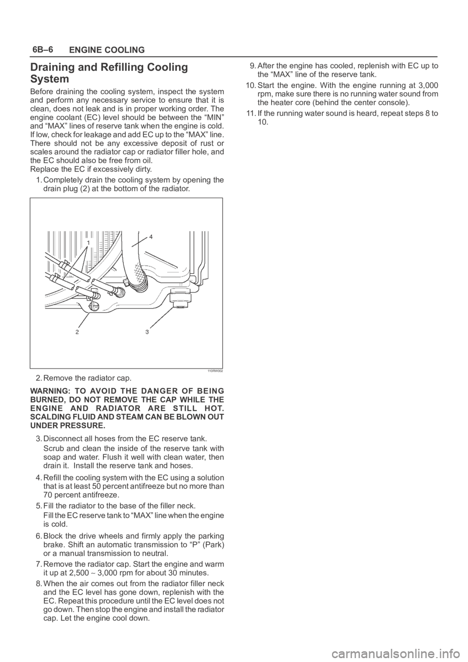
1. Completely drain the cooling system by opening the
drain plug (2) at the bottom of the radiator.
110RW002
2. Remove the radiator cap.
WARNING: TO AVOID THE DANGER OF BEING
BURNED, DO NOT REMOVE THE CAP WHILE THE
ENGINE AND RADIATOR ARE STILL HOT.
SCALDING FLUID AND STEAM CAN BE BLOWN OUT
UNDER PRESSURE.
3. Disconnect all hoses from the EC reserve tank.
Scrub and clean the inside of the reserve tank with
soap and water. Flush it well with clean water, then
drain it. Install the reserve tank and hoses.
4. Refill the cooling system with the EC using a solution
that is at least 50 percent antifreeze but no more than
70 percent antifreeze.
5. Fill the radiator to the base of the filler neck.
Fill the EC reserve tank to “MAX” line when the engine
is cold.
6. Block the drive wheels and firmly apply the parking
brake. Shift an automatic transmission to “P” (Park)
or a manual transmission to neutral.
7. Remove the radiator cap. Start the engine and warm
it up at 2,500
3,000 rpm for about 30 minutes.
8. When the air comes out from the radiator filler neck
and the EC level has gone down, replenish with the
EC. Repeat this procedure until the EC level does not
go down. Then stop the engine and install the radiator
cap. Let the engine cool down.9. After the engine has cooled, replenish with EC up to
the “MAX” line of the reserve tank.
10. Start the engine. With the engine running at 3,000
rpm, make sure there is no running water sound from
the heater core (behind the center console).
11. If the running water sound is heard, repeat steps 8 to
10.
Page 1064 of 6000
ENGINE COOLING6B–11
Cap tester: 5–8840–0277–0
Adapter: 5–8840–2603–0
110RS005
Installation
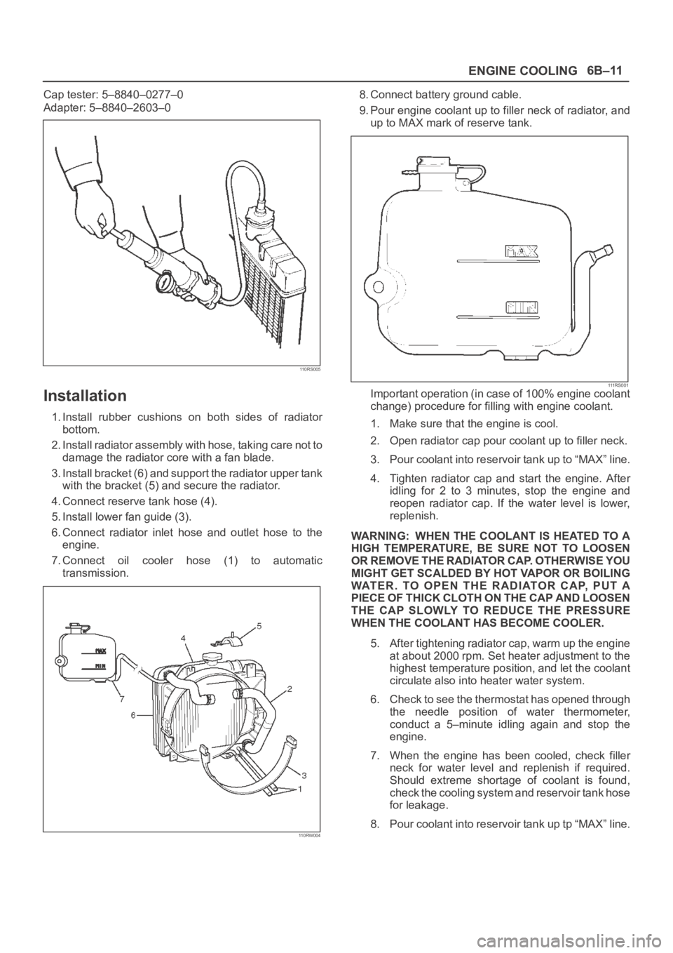
1. Install rubber cushions on both sides of radiator
bottom.
2. Install radiator assembly with hose, taking care not to
damage the radiator core with a fan blade.
3. Install bracket (6) and support the radiator upper tank
with the bracket (5) and secure the radiator.
4. Connect reserve tank hose (4).
5. Install lower fan guide (3).
6. Connect radiator inlet hose and outlet hose to the
engine.
7. Connect oil cooler hose (1) to automatic
transmission.
110RW004
8. Connect battery ground cable.
9. Pour engine coolant up to filler neck of radiator, and
up to MAX mark of reserve tank.
111 R S 0 0 1Important operation (in case of 100% engine coolant
change) procedure for filling with engine coolant.
1. Make sure that the engine is cool.
2. Open radiator cap pour coolant up to filler neck.
3. Pour coolant into reservoir tank up to “MAX” line.
4. Tighten radiator cap and start the engine. After
idling for 2 to 3 minutes, stop the engine and
reopen radiator cap. If the water level is lower,
replenish.
WARNING: WHEN THE COOLANT IS HEATED TO A
HIGH TEMPERATURE, BE SURE NOT TO LOOSEN
OR REMOVE THE RADIATOR CAP. OTHERWISE YOU
MIGHT GET SCALDED BY HOT VAPOR OR BOILING
WATER. TO OPEN THE RADIATOR CAP, PUT A
PIECE OF THICK CLOTH ON THE CAP AND LOOSEN
THE CAP SLOWLY TO REDUCE THE PRESSURE
WHEN THE COOLANT HAS BECOME COOLER.
5. After tightening radiator cap, warm up the engine
at about 2000 rpm. Set heater adjustment to the
highest temperature position, and let the coolant
circulate also into heater water system.
6. Check to see the thermostat has opened through
the needle position of water thermometer,
conduct a 5–minute idling again and stop the
engine.
7. When the engine has been cooled, check filler
neck for water level and replenish if required.
Should extreme shortage of coolant is found,
check the cooling system and reservoir tank hose
for leakage.
8. Pour coolant into reservoir tank up tp “MAX” line.
Page 1070 of 6000
6C–3
ENGINE FUEL
Adhere to all Notices and Cautions.
All gasoline engines are designed to use only unleaded
gasoline. Unleaded gasoline must be used for proper
emission control system operation.
Its use will also minimize spark plug fouling and extend
engine oil life. Using leaded gasoline can damage the
emission control system and could result in loss of
emission warranty coverage.
All cars are equipped with an Evaporative Emission
Control System. The purpose of the system is to minimize
the escape of fuel vapors to the atmosphere.
Fuel Metering
The Engine Control Module (ECM) is in complete control
of this fuel delivery system during normal driving
conditions.
The intake manifold function, like that of a diesel, is used
only to let air into the engine. The fuel is injected by
separate injectors that are mounted over the intake
manifold.
The Manifold Absolute Pressure (MAP) sensor measures
the changes in the intake manifold pressure which result
from engine load and speed changes, which the MAP
sensor converts to a voltage output.
This sensor generates the voltage to change
corresponding to the flow of the air drawn into the engine.
The changing voltage is transformed into an electric
signal and provided to the ECM.
With receipt of the signals sent from the MAP sensor,
Intake Air Temperature sensor and others, the ECM
determines an appropriate fuel injection pulse width
feeding such information to the fuel injector valves to
effect an appropriate air/fuel ratio.
The Multiport Fuel Injection system utilizes an injection
system where the injectors turn on at every crankshaft
re vol u tion . Th e EC M con tro ls t he in je cto r on tim e so t ha t
the correct amount of fuel is metered depending on
driving conditions.
Two interchangeable “O” rings are used on the injector
that must be replaced when the injectors are removed.
The fuel rail is attached to the top of the intake manifold
and supplies fuel to all the injectors.
Fuel is recirculated through the rail continually while the
engine is running. This removes air and vapors from the
fuel as well as keeping the fuel cool during hot weather
operation.
The fuel pressure control valve that is mounted on the fuel
rail maintains a pressure differential across the injectors
under all operating conditions. It is accomplished by
controlling the amount of fuel that is recirculated back to
the fuel tank based on engine demand.
See Section “Driveability and Emission” for more
information and diagnosis.
Page 1077 of 6000
6C–10
ENGINE FUEL
Reuse of Quick–Connector
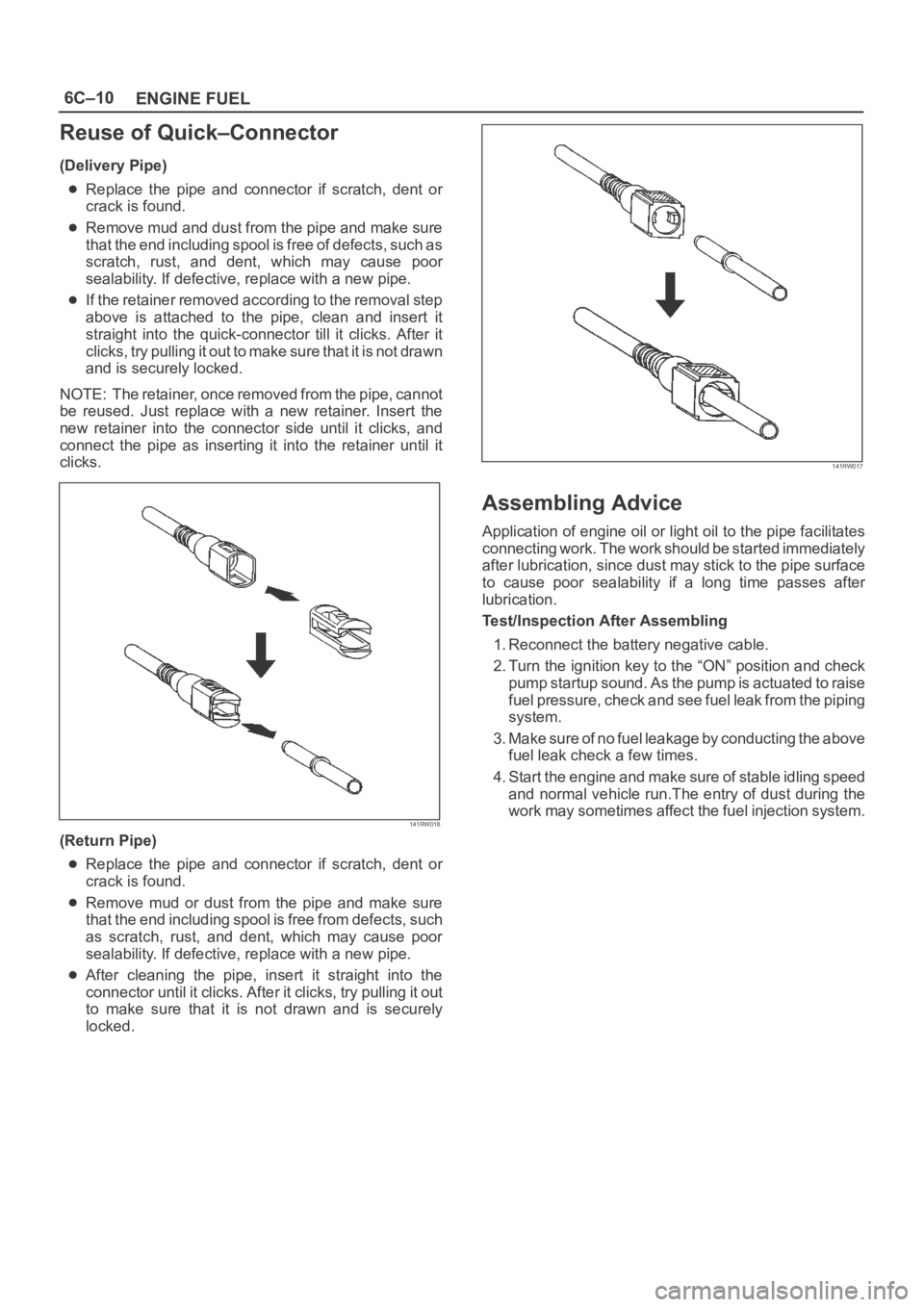
(Delivery Pipe)
Replace the pipe and connector if scratch, dent or
crack is found.
Remove mud and dust from the pipe and make sure
that the end including spool is free of defects, such as
scratch, rust, and dent, which may cause poor
sealability. If defective, replace with a new pipe.
If the retainer removed according to the removal step
above is attached to the pipe, clean and insert it
straight into the quick-connector till it clicks. After it
clicks, try pulling it out to make sure that it is not drawn
and is securely locked.
NOTE: The retainer, once removed from the pipe, cannot
be reused. Just replace with a new retainer. Insert the
new retainer into the connector side until it clicks, and
connect the pipe as inserting it into the retainer until it
clicks.
141RW018
(Return Pipe)
Replace the pipe and connector if scratch, dent or
crack is found.
Remove mud or dust from the pipe and make sure
that the end including spool is free from defects, such
as scratch, rust, and dent, which may cause poor
sealability. If defective, replace with a new pipe.
After cleaning the pipe, insert it straight into the
connector until it clicks. After it clicks, try pulling it out
to make sure that it is not drawn and is securely
locked.
141RW017
Assembling Advice
Application of engine oil or light oil to the pipe facilitates
connecting work. The work should be started immediately
after lubrication, since dust may stick to the pipe surface
to cause poor sealability if a long time passes after
lubrication.
Test/Inspection After Assembling
1. Reconnect the battery negative cable.
2. Turn the ignition key to the “ON” position and check
pump startup sound. As the pump is actuated to raise
fuel pressure, check and see fuel leak from the piping
system.
3. Make sure of no fuel leakage by conducting the above
fuel leak check a few times.
4. Start the engine and make sure of stable idling speed
and normal vehicle run.The entry of dust during the
work may sometimes affect the fuel injection system.
Page 1087 of 6000
6D2–2
IGNITION SYSTEM
General Description
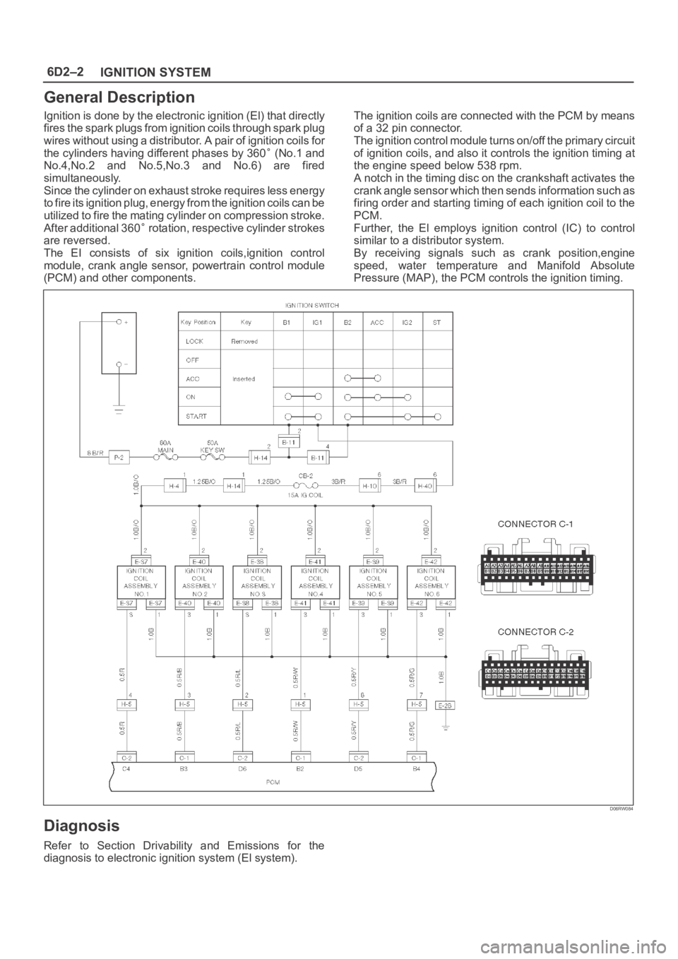
Ignition is done by the electronic ignition (El) that directly
fires the spark plugs from ignition coils through spark plug
wires without using a distributor. A pair of ignition coils for
the cylinders having different phases by 360
(No.1 and
No.4,No.2 and No.5,No.3 and No.6) are fired
simultaneously.
Since the cylinder on exhaust stroke requires less energy
to fire its ignition plug, energy from the ignition coils can be
utilized to fire the mating cylinder on compression stroke.
After additional 360
rotation, respective cylinder strokes
are reversed.
The EI consists of six ignition coils,ignition control
module, crank angle sensor, powertrain control module
(PCM) and other components.The ignition coils are connected with the PCM by means
of a 32 pin connector.
The ignition control module turns on/off the primary circuit
of ignition coils, and also it controls the ignition timing at
the engine speed below 538 rpm.
A notch in the timing disc on the crankshaft activates the
crank angle sensor which then sends information such as
firing order and starting timing of each ignition coil to the
PCM.
Further, the El employs ignition control (IC) to control
similar to a distributor system.
By receiving signals such as crank position,engine
speed, water temperature and Manifold Absolute
Pressure (MAP), the PCM controls the ignition timing.
D06RW084
Diagnosis
Refer to Section Drivability and Emissions for the
diagnosis to electronic ignition system (El system).
Page 1119 of 6000
6E–2
ENGINE DRIVEABILITY AND EMISSIONS
Primary System-Based Diagnostic 6E–50. . . . . . . . .
Primary System-Based Diagnostic 6E–50. . . . . . .
Fuel Control Heated Oxygen Sensor 6E–50. . . . .
HO2S Heater 6E–50. . . . . . . . . . . . . . . . . . . . . . . . .
Fuel Trim System Monitor Diagnostic
Operation 6E–50. . . . . . . . . . . . . . . . . . . . . . . . . . . . . .
Fuel Trim System Monitor Diagnostic
Operation 6E–50. . . . . . . . . . . . . . . . . . . . . . . . . . . .
Fuel Trim Cell Diagnostic Weights 6E–50. . . . . . .
On-Board Diagnostic (OBD) System Check 6E–51.
A/C Clutch Control Circuit Diagnosis 6E–54. . . . . . .
Electronic Ignition System Diagnosis 6E–60. . . . . . .
Fuel Metering System Check 6E–60. . . . . . . . . . . . .
Idle Air Control (IAC) Valve 6E–60. . . . . . . . . . . . . . .
Fuel System Pressure Test 6E–60. . . . . . . . . . . . . . .
Fuel Injector Coil Test Procedure and Fuel
Injector Balance Test Procedure 6E–60. . . . . . . . . .
Knock Sensor Diagnosis 6E–65. . . . . . . . . . . . . . . . .
Powertrain Control Module (PCM) Diagnosis 6E–65
Multiple PCM Information Sensor DTCS Set 6E–65
Exhaust Gas Recirculation (EGR) Diagnosis
(For except EXPORT and
SOUTH AFRICA) 6E–68. . . . . . . . . . . . . . . . . . . . . . .
Engine Tech 2 Data Definitions and Ranges 6E–68
Typical Scan Data Values 6E–70. . . . . . . . . . . . . . . .
No Malfunction Indicator Lamp (MIL) 6E–74. . . . . . .
Malfunction Indicator Lamp (MIL) “ON”
Steady 6E–77. . . . . . . . . . . . . . . . . . . . . . . . . . . . . . . .
Engine Cranks But Will Not Run 6E–79. . . . . . . . . . .
Fuel System Electrical Test 6E–85. . . . . . . . . . . . . . .
Fuel System Diagnosis 6E–88. . . . . . . . . . . . . . . . . . .
Idle Air Control (IAC) System Check 6E–93. . . . . . .
Knock Sensor (KS) System Check
(Engine Knock, Poor Performance, or Poor
Economy) 6E–95. . . . . . . . . . . . . . . . . . . . . . . . . . . . .
Exhaust Gas Recirculation (EGR) System
Check 6E–97. . . . . . . . . . . . . . . . . . . . . . . . . . . . . . . . .
Manifold Absolute Pressure (MAP) Output
Check 6E–99. . . . . . . . . . . . . . . . . . . . . . . . . . . . . . . . .
PCM Diagnostic Trouble Codes 6E–101. . . . . . . . . . .
Diagnostic Trouble Code (DTC) P0101
MAF System Performance 6E–104. . . . . . . . . . . . . . .
Diagnostic Trouble Code (DTC) P0102
MAF Sensor Circuit Low Frequency 6E–107. . . . . .
Diagnostic Trouble Code (DTC) P0103
MAF Sensor Circuit High Frequency 6E–110. . . . . .
Diagnostic Trouble Code (DTC) P0107
MAP Sensor Circuit Low Voltage 6E–112. . . . . . . . . .
Diagnostic Trouble Code (DTC) P0108
MAP Sensor Circuit High Voltage 6E–115. . . . . . . . .
Diagnostic Trouble Code (DTC) P0112
IAT Sensor Circuit Low Voltage 6E–118. . . . . . . . . . .
Diagnostic Trouble Code (DTC) P0113
IAT Sensor Circuit High Voltage 6E–121. . . . . . . . . . Diagnostic Trouble Code (DTC) P0117
ECT Sensor Circuit Low Voltage 6E–124. . . . . . . . . .
Diagnostic Trouble Code (DTC) P0118
ECT Sensor Circuit High Voltage 6E–127. . . . . . . . .
Diagnostic Trouble Code (DTC) P0121
TP System Performance 6E–130. . . . . . . . . . . . . . . . .
Diagnostic Trouble Code (DTC) P0122
TP Sensor Circuit Low Voltage 6E–133. . . . . . . . . . .
Diagnostic Trouble Code (DTC) P0123
TP Sensor Circuit High Voltage 6E–136. . . . . . . . . .
Diagnostic Trouble Code (DTC) P0131
HO2S Circuit Low Voltage Bank 1
Sensor 1 6E–139. . . . . . . . . . . . . . . . . . . . . . . . . . . . . . .
Diagnostic Trouble Code (DTC) P0132
HO2S Circuit High Voltage Bank 1
Sensor 1 6E–142. . . . . . . . . . . . . . . . . . . . . . . . . . . . . . .
Diagnostic Trouble Code (DTC) P0134
HO2S Circuit Insufficient Activity Bank 1
Sensor 1 6E–145. . . . . . . . . . . . . . . . . . . . . . . . . . . . . .
Diagnostic Trouble Code (DTC) P0151
HO2S Circuit Low Voltage Bank 2
Sensor 1 6E–148. . . . . . . . . . . . . . . . . . . . . . . . . . . . . . .
Diagnostic Trouble Code (DTC) P0152
HO2S Circuit HIGH Voltage Bank 2
Sensor 1 6E–151. . . . . . . . . . . . . . . . . . . . . . . . . . . . . . .
Diagnostic Trouble Code (DTC) P0171
Fuel Trim System Lean Bank 1 6E–154. . . . . . . . . . .
Diagnostic Trouble Code (DTC) P0172
Fuel Trim System Rich Bank 1 6E–158. . . . . . . . . . .
Diagnostic Trouble Code (DTC) P0174
Fuel Trim System Lean Bank 2 6E–162. . . . . . . . . . .
Diagnostic Trouble Code (DTC) P0175
Fuel Trim System Rich Bank 2 6E–166. . . . . . . . . . .
Diagnostic Trouble Code (DTC) P0201
Injector 1 Control Circuit 6E–170. . . . . . . . . . . . . . . . .
Diagnostic Trouble Code (DTC) P0202
Injector 2 Control Circuit 6E–173. . . . . . . . . . . . . . . . .
Diagnostic Trouble Code (DTC) P0203
Injector 3 Control Circuit 6E–176. . . . . . . . . . . . . . . . .
Diagnostic Trouble Code (DTC) P0204
Injector 4 Control Circuit 6E–179. . . . . . . . . . . . . . . . .
Diagnostic Trouble Code (DTC) P0205
Injector 5 Control Circuit 6E–182. . . . . . . . . . . . . . . . .
Diagnostic Trouble Code (DTC) P0206
Injector 6 Control Circuit 6E–185. . . . . . . . . . . . . . . . .
Diagnostic Trouble Code (DTC) P0325
KS Module Circuit 6E–188. . . . . . . . . . . . . . . . . . . . . .
Diagnostic Trouble Code (DTC) P0327
KS Sensor Circuit 6E–190. . . . . . . . . . . . . . . . . . . . . . .
Diagnostic Trouble Code (DTC) P0336
58X Reference Signal Circuit 6E–193. . . . . . . . . . . . .
Diagnostic Trouble Code (DTC) P0337
CKP Sensor Circuit Low Frequency 6E–195. . . . . . .
Diagnostic Trouble Code (DTC) P0341
CMP Sensor Circuit Performance 6E–198. . . . . . . . .
Diagnostic Trouble Code (DTC) P0342
CMP Sensor Circuit Low 6E–202. . . . . . . . . . . . . . . . .
Page 1121 of 6000
6E–4
ENGINE DRIVEABILITY AND EMISSIONS
Knock Sensor 6E–337. . . . . . . . . . . . . . . . . . . . . . . . .
Linear Exhaust Gas Recirculation (EGR)
Control 6E–337. . . . . . . . . . . . . . . . . . . . . . . . . . . . . .
Mass Air Flow (MAF) Sensor 6E–337. . . . . . . . . . . .
Manifold Absolute Pressure (MAP) Sensor 6E–338
Powertrain Control Module (PCM) 6E–338. . . . . . .
PCM Function 6E–338. . . . . . . . . . . . . . . . . . . . . . . . .
PCM Components 6E–339. . . . . . . . . . . . . . . . . . . . .
PCM Voltage Description 6E–339. . . . . . . . . . . . . . .
PCM Input/Outputs 6E–339. . . . . . . . . . . . . . . . . . . .
PCM Service Precautions 6E–339. . . . . . . . . . . . . .
Reprogramming The PCM 6E–339. . . . . . . . . . . . . .
Throttle Position (TP) Sensor 6E–339. . . . . . . . . . .
Transmission Fluid Temperature (TFT)
Sensor 6E–340. . . . . . . . . . . . . . . . . . . . . . . . . . . . . .
Transmission Range Switch 6E–340. . . . . . . . . . . . .
Vehicle Speed Sensor (VSS) 6E–340. . . . . . . . . . . .
Use of Circuit Testing Tools 6E–340. . . . . . . . . . . . .
Aftermarket Electrical and Vacuum
Equipment 6E–340. . . . . . . . . . . . . . . . . . . . . . . . . . .
Electrostatic Discharge Damage 6E–341. . . . . . . . .
Upshift Lamp 6E–341. . . . . . . . . . . . . . . . . . . . . . . . .
General Description (Air Induction) 6E–341. . . . . . . .
Air Induction System 6E–341. . . . . . . . . . . . . . . . . . .
General Description (Fuel Metering) 6E–341. . . . . . .
Acceleration Mode 6E–341. . . . . . . . . . . . . . . . . . . . .
Accelerator Controls 6E–341. . . . . . . . . . . . . . . . . . .
Battery Voltage Correction Mode 6E–341. . . . . . . .
CMP Signal 6E–341. . . . . . . . . . . . . . . . . . . . . . . . . . .
Clear Flood Mode 6E–342. . . . . . . . . . . . . . . . . . . . .
Deceleration Mode 6E–342. . . . . . . . . . . . . . . . . . . .
Engine Speed/Vehicle Speed/Fuel
Disable Mode 6E–342. . . . . . . . . . . . . . . . . . . . . . . .
Fuel Cutoff Mode 6E–342. . . . . . . . . . . . . . . . . . . . . .
Fuel Injector 6E–342. . . . . . . . . . . . . . . . . . . . . . . . . .
Fuel Metering System Components 6E–342. . . . . . Fuel Metering System Purpose 6E–342. . . . . . . . . .
Fuel Pressure Regulator 6E–343. . . . . . . . . . . . . . . .
Fuel Pump Electrical Circuit 6E–343. . . . . . . . . . . . .
Fuel Rail 6E–343. . . . . . . . . . . . . . . . . . . . . . . . . . . . .
Idle Air Control (IAC) Valve 6E–343. . . . . . . . . . . . .
Run Mode 6E–344. . . . . . . . . . . . . . . . . . . . . . . . . . . .
Starting Mode 6E–344. . . . . . . . . . . . . . . . . . . . . . . . .
Throttle Body Unit 6E–344. . . . . . . . . . . . . . . . . . . . .
General Description (Electronic Ignition
System) 6E–344. . . . . . . . . . . . . . . . . . . . . . . . . . . . . . .
Camshaft Position (CMP) Sensor 6E–344. . . . . . . .
Crankshaft Position (CKP) Sensor 6E–345. . . . . . .
Electronic Ignition 6E–345. . . . . . . . . . . . . . . . . . . . .
Ignition Coils 6E–345. . . . . . . . . . . . . . . . . . . . . . . . . .
Ignition Control 6E–345. . . . . . . . . . . . . . . . . . . . . . . .
Ignition Control PCM Output 6E–347. . . . . . . . . . . .
Knock Sensor (KS) PCM Input 6E–347
. . . . . . . . . .
Powertrain Control Module (PCM) 6E–347. . . . . . .
Spark Plug 6E–347. . . . . . . . . . . . . . . . . . . . . . . . . . . .
A/C Clutch Diagnosis 6E–349. . . . . . . . . . . . . . . . . . . .
A/C Clutch Circuit Operation 6E–349. . . . . . . . . . . .
A/C Clutch Circuit Purpose 6E–349. . . . . . . . . . . . .
A/C Request Signal 6E–349. . . . . . . . . . . . . . . . . . . .
General Description (Exhaust Gas
Recirculation (EGR) System) 6E–349. . . . . . . . . . . . .
EGR Purpose 6E–349. . . . . . . . . . . . . . . . . . . . . . . . .
Linear EGR Valve 6E–349. . . . . . . . . . . . . . . . . . . . .
Linear EGR Control 6E–349. . . . . . . . . . . . . . . . . . . .
Linear EGR Valve Operation and Results
of Incorrect Operation 6E–349. . . . . . . . . . . . . . . . .
EGR Pintle Position Sensor 6E–350. . . . . . . . . . . . .
General Description (Positive Crankcase
Ventilation (PCV) System) 6E–350. . . . . . . . . . . . . . .
Crankcase Ventilation System Purpose 6E–350. . .
Crankcase Ventilation System Operation 6E–350.
Page 1136 of 6000
6E–19 ENGINE DRIVEABILITY AND EMISSIONS
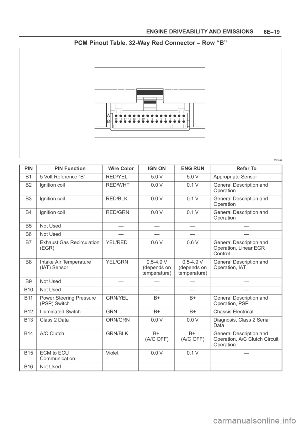
PCM Pinout Table, 32-Way Red Connector – Row “B”
TS23344
PINPIN FunctionWire ColorIGN ONENG RUNRefer To
B15 Volt Reference “B”RED/YEL5.0 V5.0 VAppropriate Sensor
B2lgnition coilRED/WHT0.0 V0.1 VGeneral Description and
Operation
B3lgnition coilRED/BLK0.0 V0.1 VGeneral Description and
Operation
B4lgnition coilRED/GRN0.0 V0.1 VGeneral Description and
Operation
B5Not Used————
B6Not Used————
B7Exhaust Gas Recirculation
(EGR)YEL/RED0.6 V0.6 VGeneral Description and
Operation, Linear EGR
Control
B8Intake Air Temperature
(IAT) SensorYEL/GRN0.5-4.9 V
(depends on
temperature)0.5-4.9 V
(depends on
temperature)General Description and
Operation, IAT
B9Not Used————
B10Not Used————
B11Power Steering Pressure
(PSP) SwitchGRN/YELB+B+General Description and
Operation, PSP
B12Illuminated SwitchGRNB+B+Chassis Electrical
B13Class 2 DataORN/GRN0.0 V0.0 VDiagnosis, Class 2 Serial
Data
B14A/C ClutchGRN/BLKB+
(A/C OFF)B+
(A/C OFF)General Description and
Operation, A/C Clutch Circuit
Operation
B15ECM to ECU
CommunicationViolet0.0 V0.1 V—
B16Not Used————