1998 OPEL FRONTERA oil pressure
[x] Cancel search: oil pressurePage 1394 of 6000
6E–277 ENGINE DRIVEABILITY AND EMISSIONS
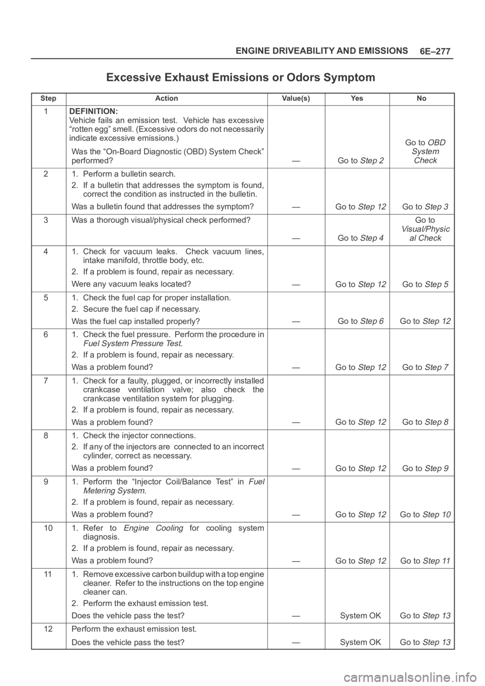
Excessive Exhaust Emissions or Odors Symptom
StepActionVa l u e ( s )Ye sNo
1DEFINITION:
Vehicle fails an emission test. Vehicle has excessive
“rotten egg” smell. (Excessive odors do not necessarily
indicate excessive emissions.)
Was the “On-Board Diagnostic (OBD) System Check”
performed?
—Go to Step 2
Go to OBD
System
Check
21. Perform a bulletin search.
2. If a bulletin that addresses the symptom is found,
correct the condition as instructed in the bulletin.
Was a bulletin found that addresses the symptom?
—Go to Step 12Go to Step 3
3Was a thorough visual/physical check performed?
—Go to Step 4
Go to
Visual/Physic
al Check
41. Check for vacuum leaks. Check vacuum lines,
intake manifold, throttle body, etc.
2. If a problem is found, repair as necessary.
Were any vacuum leaks located?
—Go to Step 12Go to Step 5
51. Check the fuel cap for proper installation.
2. Secure the fuel cap if necessary.
Was the fuel cap installed properly?
—Go to Step 6Go to Step 12
61. Check the fuel pressure. Perform the procedure in
Fuel System Pressure Test.
2. If a problem is found, repair as necessary.
Was a problem found?
—Go to Step 12Go to Step 7
71. Check for a faulty, plugged, or incorrectly installed
crankcase ventilation valve; also check the
crankcase ventilation system for plugging.
2. If a problem is found, repair as necessary.
Was a problem found?
—Go to Step 12Go to Step 8
81. Check the injector connections.
2. If any of the injectors are connected to an incorrect
cylinder, correct as necessary.
Was a problem found?
—Go to Step 12Go to Step 9
91. Perform the “Injector Coil/Balance Test” in Fuel
Metering System
.
2. If a problem is found, repair as necessary.
Was a problem found?
—Go to Step 12Go to Step 10
101. Refer to Engine Cooling for cooling system
diagnosis.
2. If a problem is found, repair as necessary.
Was a problem found?
—Go to Step 12Go to Step 11
111. Remove excessive carbon buildup with a top engine
cleaner. Refer to the instructions on the top engine
cleaner can.
2. Perform the exhaust emission test.
Does the vehicle pass the test?
—System OKGo to Step 13
12Perform the exhaust emission test.
Does the vehicle pass the test?
—System OKGo to Step 13
Page 1397 of 6000
6E–280
ENGINE DRIVEABILITY AND EMISSIONS
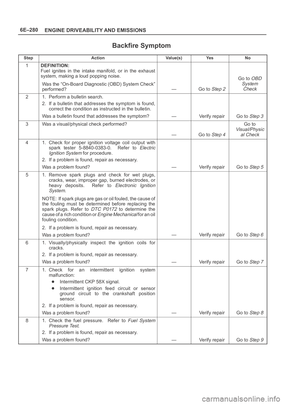
Backfire Symptom
StepActionVa l u e ( s )Ye sNo
1DEFINITION:
Fuel ignites in the intake manifold, or in the exhaust
system, making a loud popping noise.
Was the “On-Board Diagnostic (OBD) System Check”
performed?
—Go to Step 2
Go to OBD
System
Check
21. Perform a bulletin search.
2. If a bulletin that addresses the symptom is found,
correct the condition as instructed in the bulletin.
Was a bulletin found that addresses the symptom?
—Verify repairGo to Step 3
3Was a visual/physical check performed?
—Go to Step 4
Go to
Visual/Physic
al Check
41. Check for proper ignition voltage coil output with
spark tester 5-8840-0383-0. Refer to
Electric
Ignition System
for procedure.
2. If a problem is found, repair as necessary.
Was a problem found?
—Verify repairGo to Step 5
51. Remove spark plugs and check for wet plugs,
cracks, wear, improper gap, burned electrodes, or
heavy deposits. Refer to
Electronic Ignition
System
.
NOTE: If spark plugs are gas or oil fouled, the cause of
the fouling must be determined before replacing the
spark plugs. Refer to
DTC P0172 to determine the
cause of a rich condition or
Engine Mechanical for an oil
fouling condition.
2. If a problem is found, repair as necessary.
Was a problem found?
—Verify repairGo to Step 6
61. Visually/physically inspect the ignition coils for
cracks.
2. If a problem is found, repair as necessary.
Was a problem found?
—Verify repairGo to Step 7
71. Check for an intermittent ignition system
malfunction:
Intermittent CKP 58X signal.
Intermittent ignition feed circuit or sensor
ground circuit to the crankshaft position
sensor.
2. If a problem is found, repair as necessary.
Was a problem found?
—Verify repairGo to Step 8
81. Check the fuel pressure. Refer to Fuel System
Pressure Test
.
2. If a problem is found, repair as necessary.
Was a problem found?
—Verify repairGo to Step 9
Page 1400 of 6000
6E–283 ENGINE DRIVEABILITY AND EMISSIONS
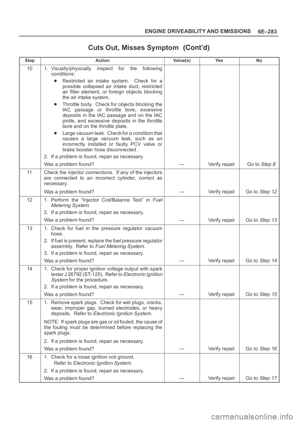
Cuts Out, Misses Symptom
StepNo Ye s Va l u e ( s ) Action
101. Visually/physically inspect for the following
conditions:
Restricted air intake system. Check for a
possible collapsed air intake duct, restricted
air filter element, or foreign objects blocking
the air intake system.
Throttle body. Check for objects blocking the
IAC passage or throttle bore, excessive
deposits in the IAC passage and on the IAC
pintle, and excessive deposits in the throttle
bore and on the throttle plate.
Large vacuum leak. Check for a condition that
causes a large vacuum leak, such as an
incorrectly installed or faulty PCV valve or
brake booster hose disconnected .
2. If a problem is found, repair as necessary.
Was a problem found?
—Verify repairGo to Step 8
11Check the injector connections. If any of the injectors
are connected to an incorrect cylinder, correct as
necessary.
Was a problem found?
—Verify repairGo to Step 12
121. Perform the “Injector Coil/Balance Test” in Fuel
Metering System
.
2. If a problem is found, repair as necessary.
Was a problem found?
—Verify repairGo to Step 13
131. Check for fuel in the pressure regulator vacuum
hose.
2. If fuel is present, replace the fuel pressure regulator
assembly. Refer to
Fuel Metering System.
3. If a problem is found, repair as necessary.
Was a problem found?
—Verify repairGo to Step 14
141. Check for proper ignition voltage output with spark
tester J 26792 (ST-125). Refer to
Electronic Ignition
System
for the procedure.
2. If a problem is found, repair as necessary.
Was a problem found?
—Verify repairGo to Step 15
151. Remove spark plugs. Check for wet plugs, cracks,
wear, improper gap, burned electrodes, or heavy
deposits. Refer to
Electronic Ignition System.
NOTE: If spark plugs are gas or oil fouled, the cause of
the fouling must be determined before replacing the
spark plugs.
2. If a problem is found, repair as necessary.
Was a problem found?
—Verify repairGo to Step 16
161. Check for a loose ignition coil ground.
Refer to
Electronic Ignition System.
2. If a problem is found, repair as necessary.
Was a problem found?
—Verify repairGo to Step 17
Page 1432 of 6000
6E–315 ENGINE DRIVEABILITY AND EMISSIONS
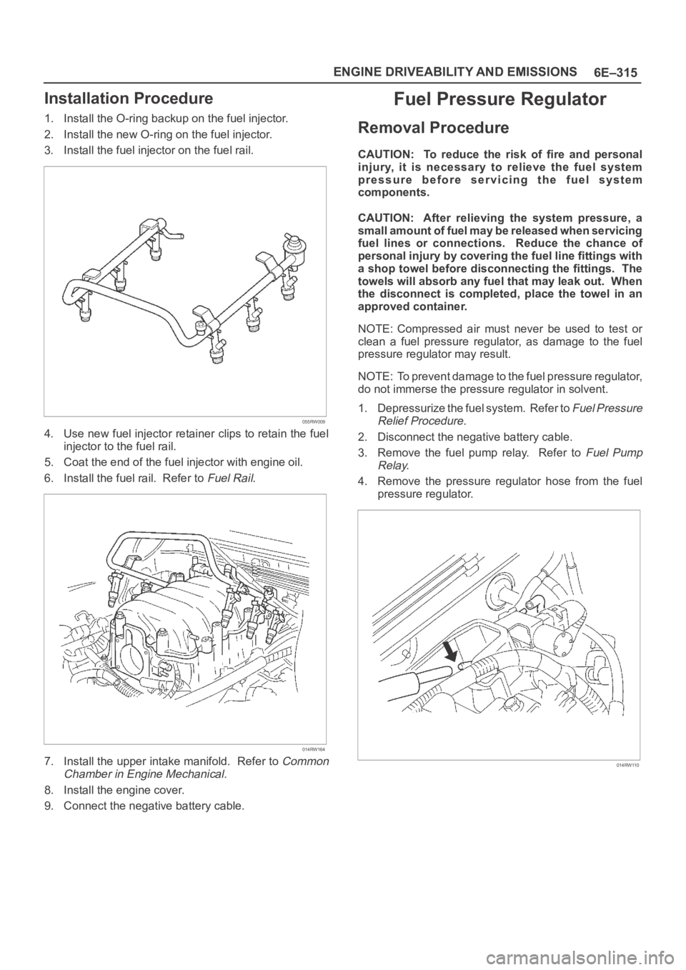
Installation Procedure
1. Install the O-ring backup on the fuel injector.
2. Install the new O-ring on the fuel injector.
3. Install the fuel injector on the fuel rail.
055RW009
4. Use new fuel injector retainer clips to retain the fuel
injector to the fuel rail.
5. Coat the end of the fuel injector with engine oil.
6. Install the fuel rail. Refer to
Fuel Rail.
014RW164
7. Install the upper intake manifold. Refer to Common
Chamber in Engine Mechanical.
8. Install the engine cover.
9. Connect the negative battery cable.
Fuel Pressure Regulator
Removal Procedure
CAUTION: To reduce the risk of fire and personal
injury, it is necessary to relieve the fuel system
pressure before servicing the fuel system
components.
CAUTION: After relieving the system pressure, a
small amount of fuel may be released when servicing
fuel lines or connections. Reduce the chance of
personal injury by covering the fuel line fittings with
a shop towel before disconnecting the fittings. The
towels will absorb any fuel that may leak out. When
the disconnect is completed, place the towel in an
approved container.
NOTE: Compressed air must never be used to test or
clean a fuel pressure regulator, as damage to the fuel
pressure regulator may result.
NOTE: To prevent damage to the fuel pressure regulator,
do not immerse the pressure regulator in solvent.
1. Depressurize the fuel system. Refer to
Fuel Pressure
Relief Procedure
.
2. Disconnect the negative battery cable.
3. Remove the fuel pump relay. Refer to
Fuel Pump
Relay
.
4. Remove the pressure regulator hose from the fuel
pressure regulator.
014RW110
Page 1466 of 6000
6E–349 ENGINE DRIVEABILITY AND EMISSIONS
Damage during re-gapping can happen if the gapping
tool is pushed against the center electrode or the
insulator around it, causing the insulator to crack.
When re-gapping a spark plug, make the adjustment
by bending only the ground side terminal, keeping the
tool clear of other parts.
”Heat shock” breakage in the lower insulator tip
generally occurs during several engine operating
conditions (high speeds or heavy loading) and may be
caused by over-advanced timing or low grade fuels.
Heat shock refers to a rapid increase in the tip
temperature that causes the insulator material to
crack.
Spark plugs with less than the recommended amount of
service can sometimes be cleaned and re-gapped , then
returned to service. However, if there is any doubt about
the serviceability of a spark plug, replace it. Spark plugs
with cracked or broken insulators should always be
replaced.
A/C Clutch Diagnosis
A/C Clutch Circuit Operation
A 12-volt signal is supplied to the A/C request input of the
PCM when the A/C is selected through the A/C control
switch.
The A/C compressor clutch relay is controlled through the
PCM. This allows the PCM to modify the idle air control
position prior to the A/C clutch engagement for better idle
quality. If the engine operating conditions are within their
specified calibrated acceptable ranges, the PCM will
enable the A/C compressor relay. This is done by
providing a ground path for the A/C relay coil within the
PCM. When the A/C compressor relay is enabled,
battery voltage is supplied to the compressor clutch coil.
The PCM will enable the A/C compressor clutch
whenever the engine is running and the A/C has been
requested. The PCM will not enable the A/C compressor
clutch if any of the following conditions are met:
The throttle is greater than 90%.
The engine speed is greater than 6315 RPM.
The ECT is greater than 119C (246F).
The IAT is less than 5C (41F).
The throttle is more than 80% open.
A/C Clutch Circuit Purpose
The A/C compressor operation is controlled by the
powertrain control module (PCM) for the following
reasons:
It improvises idle quality during compressor clutch
engagement.
It improvises wide open throttle (WOT) performance.
It provides A/C compressor protection from operation
with incorrect refrigerant pressures.
The A/C electrical system consists of the following
components:
The A/C control head.
The A/C refrigerant pressure switches.
The A/C compressor clutch.
The A/C compressor clutch relay.
The PCM.
A/C Request Signal
This signal tells the PCM when the A/C mode is selected
at the A/C control head. The PCM uses this to adjust the
idle speed before turning on the A/C clutch. The A/C
compressor will be inoperative if this signal is not
available to the PCM.
Refer to
A/C Clutch Circuit Diagnosis for A/C wiring
diagrams and diagnosis for A/C electrical system.
General Description (Exhaust Gas
Recirculation (EGR) System)
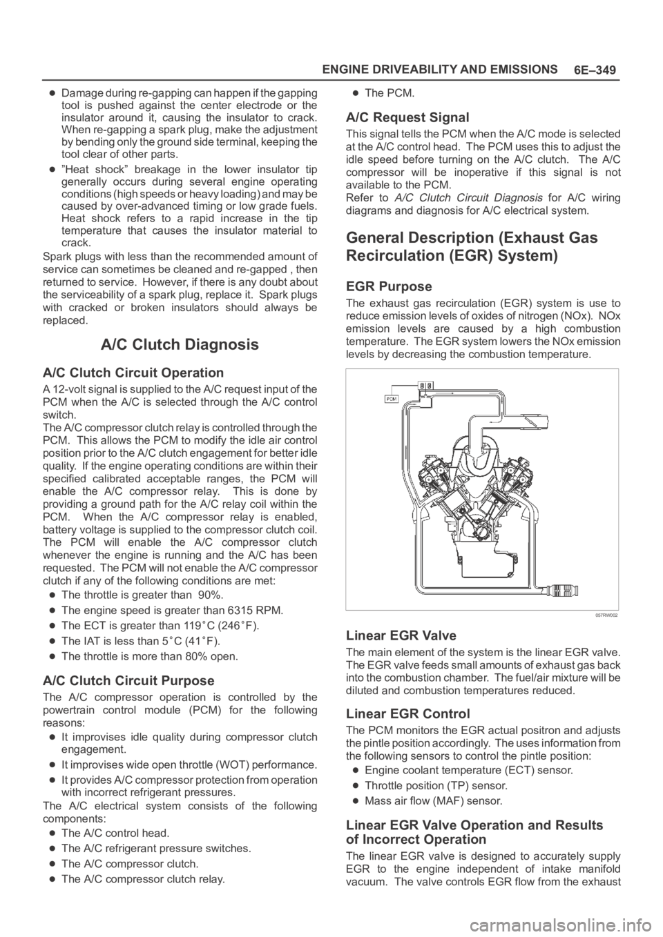
EGR Purpose
The exhaust gas recirculation (EGR) system is use to
reduce emission levels of oxides of nitrogen (NOx). NOx
emission levels are caused by a high combustion
temperature. The EGR system lowers the NOx emission
levels by decreasing the combustion temperature.
057RW002
Linear EGR Valve
The main element of the system is the linear EGR valve.
The EGR valve feeds small amounts of exhaust gas back
into the combustion chamber. The fuel/air mixture will be
diluted and combustion temperatures reduced.
Linear EGR Control
The PCM monitors the EGR actual positron and adjusts
the pintle position accordingly. The uses information from
the following sensors to control the pintle position:
Engine coolant temperature (ECT) sensor.
Throttle position (TP) sensor.
Mass air flow (MAF) sensor.
Linear EGR Valve Operation and Results
of Incorrect Operation
The linear EGR valve is designed to accurately supply
EGR to the engine independent of intake manifold
vacuum. The valve controls EGR flow from the exhaust
Page 1481 of 6000
6G–2
ENGINE LUBRICATION
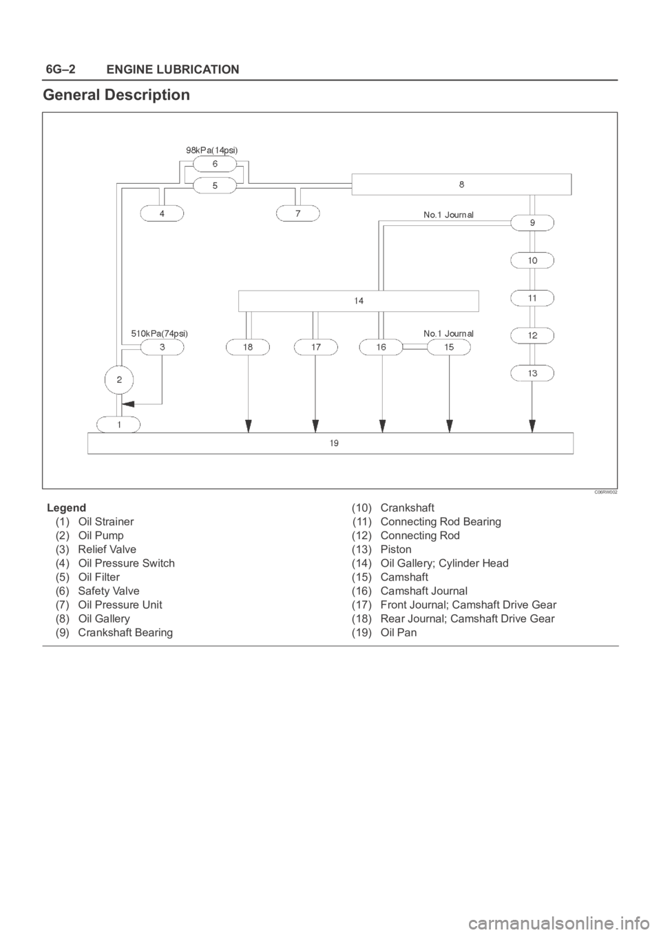
General Description
C06RW002
Legend
(1) Oil Strainer
(2) Oil Pump
(3) Relief Valve
(4) Oil Pressure Switch
(5) Oil Filter
(6) Safety Valve
(7) Oil Pressure Unit
(8) Oil Gallery
(9) Crankshaft Bearing(10) Crankshaft
(11) Connecting Rod Bearing
(12) Connecting Rod
(13) Piston
(14) Oil Gallery; Cylinder Head
(15) Camshaft
(16) Camshaft Journal
(17) Front Journal; Camshaft Drive Gear
(18) Rear Journal; Camshaft Drive Gear
(19) Oil Pan
Page 1736 of 6000

ENGINE MECHANICAL 6A – 3
SERVICE INFORMATION
MAIN DATA AND SPECIFICATION
Engine type Diesel, four cycle water cooled inline
Camshaft type DOHC
Number of cylinders 4
Bore x stroke (mm) 95.4 x 104.9
Total piston displacement (cc) 2999
Compression ratio (to 1) 19.0
For Europe : 18.5
Engine weight (dry) N (kg/lb) 2492 (254/560) (A/T)
For Europe : 2422 (247/545) (A/T)
2649 (270/593) (M/T)
For Europe : 2697 (275/606) (M/T)
Engine idling speed (Reference) RPM 720
Compression pressure kpa (kg/cm
2/psi)-rpm 3040 (31/441)-200
Firing order 1–3–4–2
VALVE SYSTEM
Intake valves open at: B.T.D.C. 3°
close at: A.B.D.C. 57.6°
Exhaust valves open at: B.B.D.C. 56.5°
close at: A.T.D.C. 5°
Valve clearance (at cold) mm (in)
intake: 0.15 (0.006)
exhaust: 0.25 (0.01)
Oil filter Full flow and bypass combined type
Oil capacity (Original factory fill or rebuilt engine) 9.0 liters (7.9 US quarts)
Oil capacity (Service change)
with filter change 6.0 liters (6.3 US quarts)
without filter change 5.0 liters (5.3 US quarts)
Oil cooler Water cooled type
Inter cooler Air cooled type
Turbocharger method
Control method Wastegate control
Lubrication Pressurized control
Cooling method Coolant cooled
Crankshaft
As tufftriding (Nitrizing treatment) is applied to increase
crankshaft strength, crankpins and journals should not
be reground.
Piston Cooling
An oiling jet device for piston cooling is provided in the
lubricating oil circuit from the cylinder block oil gallery
via a check valve.
Take care not to damage any oiling jet when removing
and installing piston and connecting assembly.
Fuel Injection System
The injection system is oil rail type.
Quick On Start 4 System
QOS4 preheating system which features a quick-on
glow plug with thermometer control of the glowing time
and the afterglow time function, is applied.
Page 1753 of 6000
6A – 20 ENGINE MECHANICAL
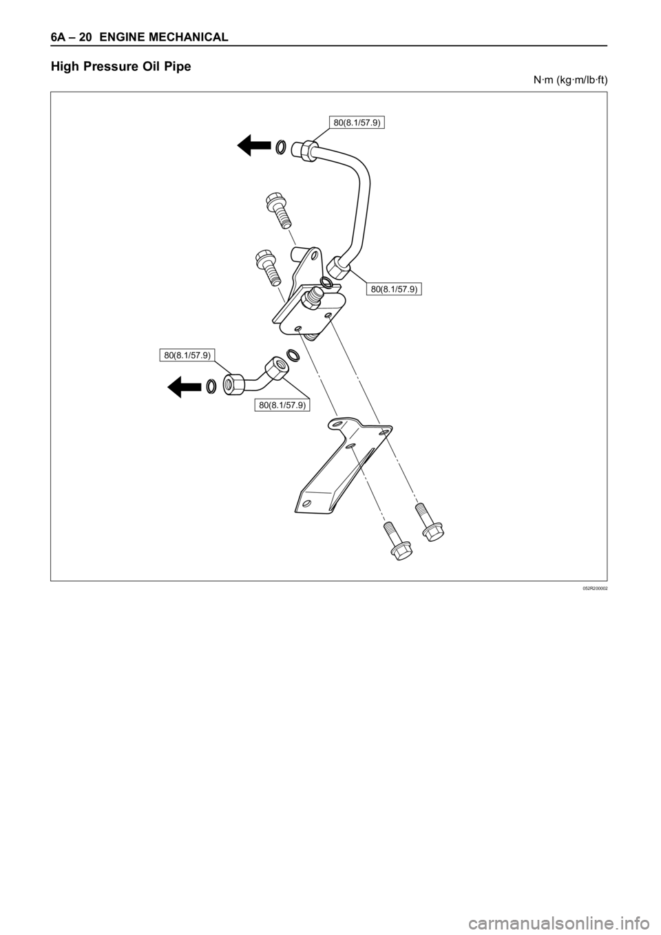
High Pressure Oil Pipe
Nꞏm (kgꞏm/lbꞏft)
80(8.1/57.9)
80(8.1/57.9)
80(8.1/57.9)
80(8.1/57.9)
052R200002