1998 OPEL FRONTERA sensor
[x] Cancel search: sensorPage 1420 of 6000
6E–303 ENGINE DRIVEABILITY AND EMISSIONS
4. Check the transfer case oil level. Add fluid if
necessary.
5. Connect the negative battery cable.
Air Cleaner/Air Filter
Removal Procedure
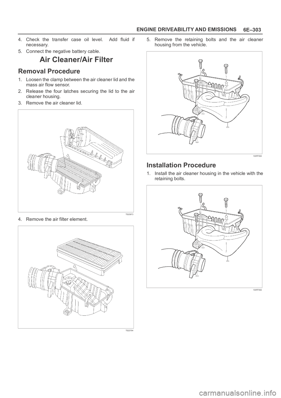
1. Loosen the clamp between the air cleaner lid and the
mass air flow sensor.
2. Release the four latches securing the lid to the air
cleaner housing.
3. Remove the air cleaner lid.
TS23973
4. Remove the air filter element.
TS23794
5. Remove the retaining bolts and the air cleaner
housing from the vehicle.
130RT002
Installation Procedure
1. Install the air cleaner housing in the vehicle with the
retaining bolts.
130RT002
Page 1421 of 6000
6E–304
ENGINE DRIVEABILITY AND EMISSIONS
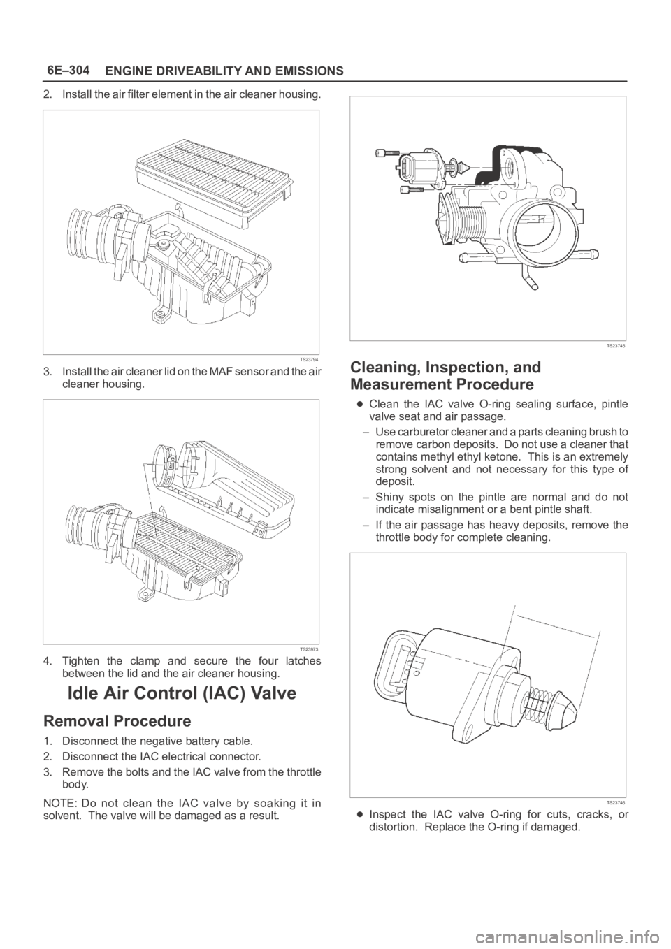
2. Install the air filter element in the air cleaner housing.
TS23794
3. Install the air cleaner lid on the MAF sensor and the air
cleaner housing.
TS23973
4. Tighten the clamp and secure the four latches
between the lid and the air cleaner housing.
Idle Air Control (IAC) Valve
Removal Procedure
1. Disconnect the negative battery cable.
2. Disconnect the IAC electrical connector.
3. Remove the bolts and the IAC valve from the throttle
body.
NOTE: Do not clean the IAC valve by soaking it in
solvent. The valve will be damaged as a result.
TS23745
Cleaning, Inspection, and
Measurement Procedure
Clean the IAC valve O-ring sealing surface, pintle
valve seat and air passage.
– Use carburetor cleaner and a parts cleaning brush to
remove carbon deposits. Do not use a cleaner that
contains methyl ethyl ketone. This is an extremely
strong solvent and not necessary for this type of
deposit.
– Shiny spots on the pintle are normal and do not
indicate misalignment or a bent pintle shaft.
– If the air passage has heavy deposits, remove the
throttle body for complete cleaning.
TS23746
Inspect the IAC valve O-ring for cuts, cracks, or
distortion. Replace the O-ring if damaged.
Page 1437 of 6000
6E–320
ENGINE DRIVEABILITY AND EMISSIONS
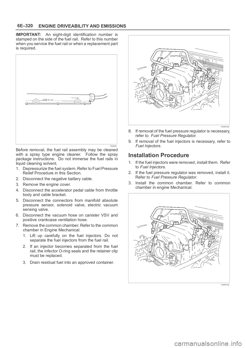
IMPORTANT:An eight-digit identification number is
stamped on the side of the fuel rail. Refer to this number
when you service the fuel rail or when a replacement part
is required.
TS24022
Before removal, the fuel rail assembly may be cleaned
with a spray type engine cleaner. Follow the spray
package instructions. Do not immerse the fuel rails in
liquid cleaning solvent.
1. Depressurize the fuel system. Refer to Fuel Pressure
Relief Procedure in this Section.
2. Disconnect the negative battery cable.
3. Remove the engine cover.
4. Disconnect the accelerator pedal cable from throttle
body and cable bracket.
5. Disconnect the connectors from manifold absolute
pressure sensor, solenoid valve, electric vacuum
sensing valve.
6. Disconnect the vacuum hose on canister VSV and
positive crankcase ventilation hose.
7. Remove the common chamber. Refer to the common
chamber in Engine Mechanical.
1. Lift up carefully on the fuel injectors. Do not
separate the fuel injectors from the fuel rail.
2. If an injector becomes separated from the fuel
rail, the infector O-ring seals and the retainer clip
must be replaced.
3. Drain residual fuel into an approved container.
014RW164
8. If removal of the fuel pressure regulator is necessary,
refer to
Fuel Pressure Regulator.
9. If removal of the fuel injectors is necessary, refer to
Fuel Injectors.
Installation Procedure
1. If the fuel injectors were removed, install them. Refer
to
Fuel Injectors.
2. If the fuel pressure regulator was removed, install it.
Refer to
Fuel Pressure Regulator.
3. Install the common chamber. Refer to common
chamber in engine Mechanical.
014RW164
Page 1438 of 6000
6E–321 ENGINE DRIVEABILITY AND EMISSIONS
4. Connect the vacuum hose on Canister VSV and
positive crankcase ventilation hose.
5. Connect the connectors to manifold absolute
pressure sensor, solenoid valve, electric vacuum
sensing valve.
6. Connect the accelerator pedal cable to throttle body
and cable bracket.
7. Install the engine cover.
8. Connect the negative battery cable.
9. Crank the engine until it starts. Cranking the engine
may take longer than usual due to trapped air in the
fuel rail and in the injectors.
Fuel Tank
Removal Procedure
1. Disconnect the negative battery cable.
2. Loosen the fuel filler cap.
3. Drain the fuel from the tank into an approved
container.
4. Install and tighten the drain plug.
Tighten
Tighten the drain plug to 20 Nꞏm (14 lb ft.).
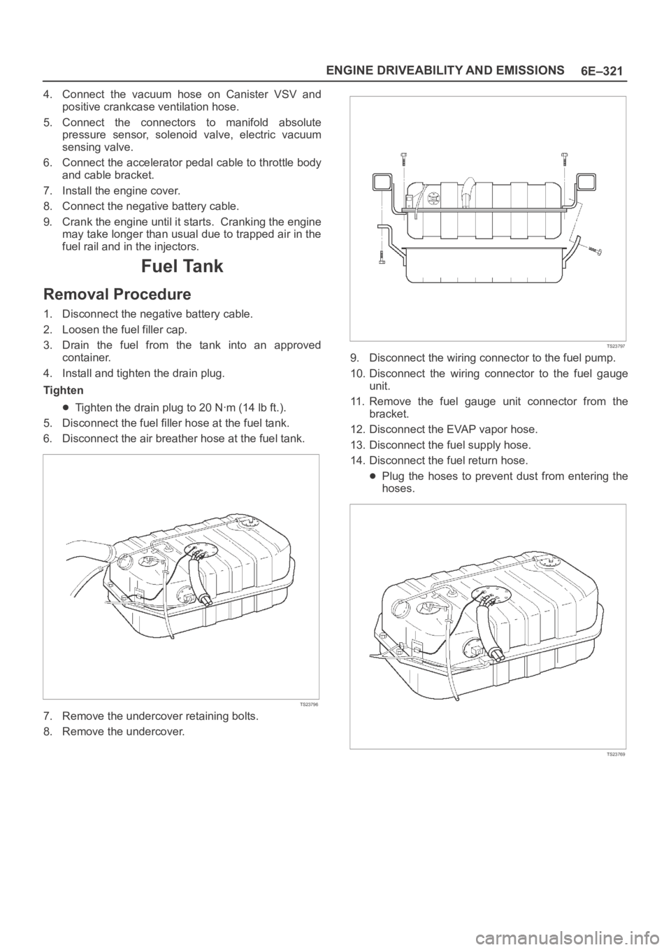
5. Disconnect the fuel filler hose at the fuel tank.
6. Disconnect the air breather hose at the fuel tank.
TS23796
7. Remove the undercover retaining bolts.
8. Remove the undercover.
TS23797
9. Disconnect the wiring connector to the fuel pump.
10. Disconnect the wiring connector to the fuel gauge
unit.
11. Remove the fuel gauge unit connector from the
bracket.
12. Disconnect the EVAP vapor hose.
13. Disconnect the fuel supply hose.
14. Disconnect the fuel return hose.
Plug the hoses to prevent dust from entering the
hoses.
TS23769
Page 1440 of 6000
6E–323 ENGINE DRIVEABILITY AND EMISSIONS
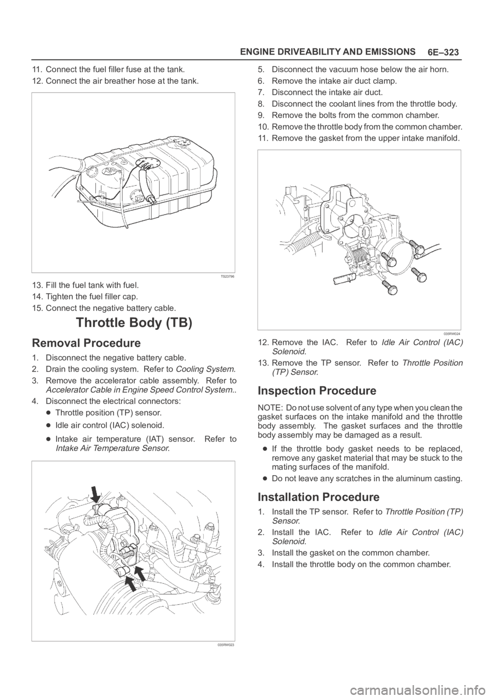
11. Connect the fuel filler fuse at the tank.
12. Connect the air breather hose at the tank.
TS23796
13. Fill the fuel tank with fuel.
14. Tighten the fuel filler cap.
15. Connect the negative battery cable.
Throttle Body (TB)
Removal Procedure
1. Disconnect the negative battery cable.
2. Drain the cooling system. Refer to
Cooling System.
3. Remove the accelerator cable assembly. Refer to
Accelerator Cable in Engine Speed Control System..
4. Disconnect the electrical connectors:
Throttle position (TP) sensor.
Idle air control (IAC) solenoid.
Intake air temperature (IAT) sensor. Refer to
Intake Air Temperature Sensor.
035RW023
5. Disconnect the vacuum hose below the air horn.
6. Remove the intake air duct clamp.
7. Disconnect the intake air duct.
8. Disconnect the coolant lines from the throttle body.
9. Remove the bolts from the common chamber.
10. Remove the throttle body from the common chamber.
11. Remove the gasket from the upper intake manifold.
035RW024
12. Remove the IAC. Refer to Idle Air Control (IAC)
Solenoid
.
13. Remove the TP sensor. Refer to
Throttle Position
(TP) Sensor
.
Inspection Procedure
NOTE: Do not use solvent of any type when you clean the
gasket surfaces on the intake manifold and the throttle
body assembly. The gasket surfaces and the throttle
body assembly may be damaged as a result.
If the throttle body gasket needs to be replaced,
remove any gasket material that may be stuck to the
mating surfaces of the manifold.
Do not leave any scratches in the aluminum casting.
Installation Procedure
1. Install the TP sensor. Refer to Throttle Position (TP)
Sensor
.
2. Install the IAC. Refer to
Idle Air Control (IAC)
Solenoid
.
3. Install the gasket on the common chamber.
4. Install the throttle body on the common chamber.
Page 1441 of 6000
6E–324
ENGINE DRIVEABILITY AND EMISSIONS
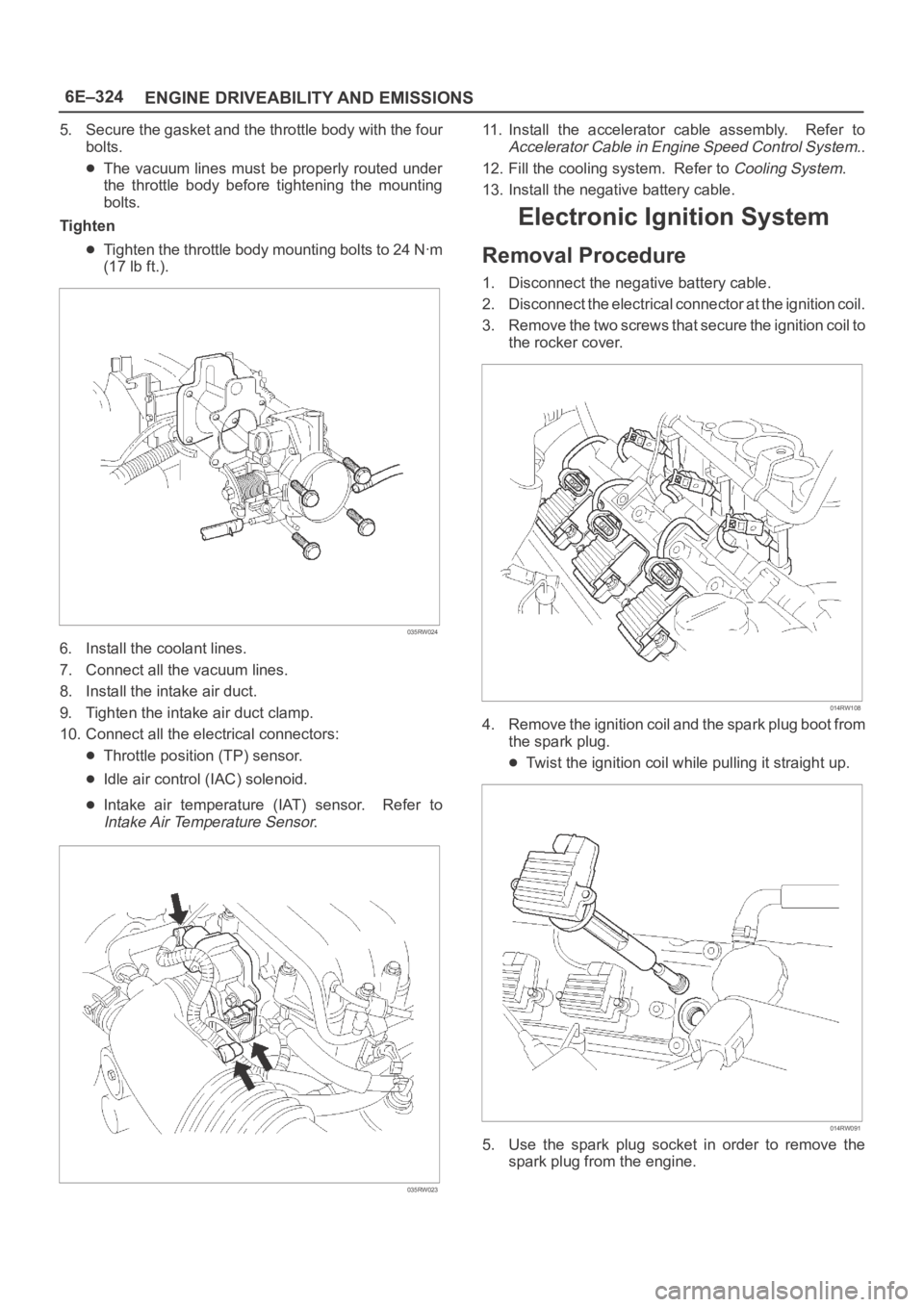
5. Secure the gasket and the throttle body with the four
bolts.
The vacuum lines must be properly routed under
the throttle body before tightening the mounting
bolts.
Tighten
Tighten the throttle body mounting bolts to 24 Nꞏm
(17 lb ft.).
035RW024
6. Install the coolant lines.
7. Connect all the vacuum lines.
8. Install the intake air duct.
9. Tighten the intake air duct clamp.
10. Connect all the electrical connectors:
Throttle position (TP) sensor.
Idle air control (IAC) solenoid.
Intake air temperature (IAT) sensor. Refer to
Intake Air Temperature Sensor.
035RW023
11. Install the accelerator cable assembly. Refer to
Accelerator Cable in Engine Speed Control System..
12. Fill the cooling system. Refer to
Cooling System.
13. Install the negative battery cable.
Electronic Ignition System
Removal Procedure
1. Disconnect the negative battery cable.
2. Disconnect the electrical connector at the ignition coil.
3. Remove the two screws that secure the ignition coil to
the rocker cover.
014RW108
4. Remove the ignition coil and the spark plug boot from
the spark plug.
Twist the ignition coil while pulling it straight up.
014RW091
5. Use the spark plug socket in order to remove the
spark plug from the engine.
Page 1447 of 6000
6E–330
ENGINE DRIVEABILITY AND EMISSIONS
Wiring and Connectors
Wiring Harness Service
The control module harness electrically connects the
control module to the various solenoids, switches and
sensors in the vehicle engine compartment and
passenger compartment.
Replace wire harnesses with the proper part number
replacement.
Because of the low amperage and voltage levels utilized
in powertrain control systems, it is essential that all wiring
in environmentally exposed areas be repaired with crimp
and seal splice sleeves.
The following wire harness repair information is intended
as a general guideline only. Refer to
Chassis Electrical f o r
all wire harness repair procedures.
Connectors and Terminals
Use care when probing a connector and when replacing
terminals. It is possible to short between opposite
terminals. Damage to components could result. Always
use jumper wires between connectors for circuit
checking. NEVER probe through Weather-Pack seals.
Use an appropriate connector test adapter kit which
contains an assortment of flexible connectors used to
probe terminals during diagnosis. Use an appropriate
fuse remover and test tool for removing a fuse and to
adapt the fuse holder to a meter for diagnosis.
Open circuits are often difficult to locate by sight because
oxidation or terminal misalignment are hidden by the
connectors. Merely wiggling a connector on a sensor, or
in the wiring harness, may temporarily correct the open
circuit. Intermittent problems may also be caused by
oxidized or loose connections.
Be certain of the type of connector/terminal before
making any connector or terminal repair. Weather-Pack
and Com-Pack III terminals look similar, but are serviced
differently.
PCM Connectors and Terminals
Removal Procedure
1. Remove the connector terminal retainer.
2. Push the wire connected to the affected terminal
through the connector face so that the terminal is
exposed.
3. Service the terminal as necessary.
Installation Procedure
1. Bend the tab on the connector to allow the terminal to
be pulled into position within the connector.
2. Pull carefully on the wire to install the connector
terminal retainer.
Wire Harness Repair: Twisted
Shielded Cable
Removal Procedure
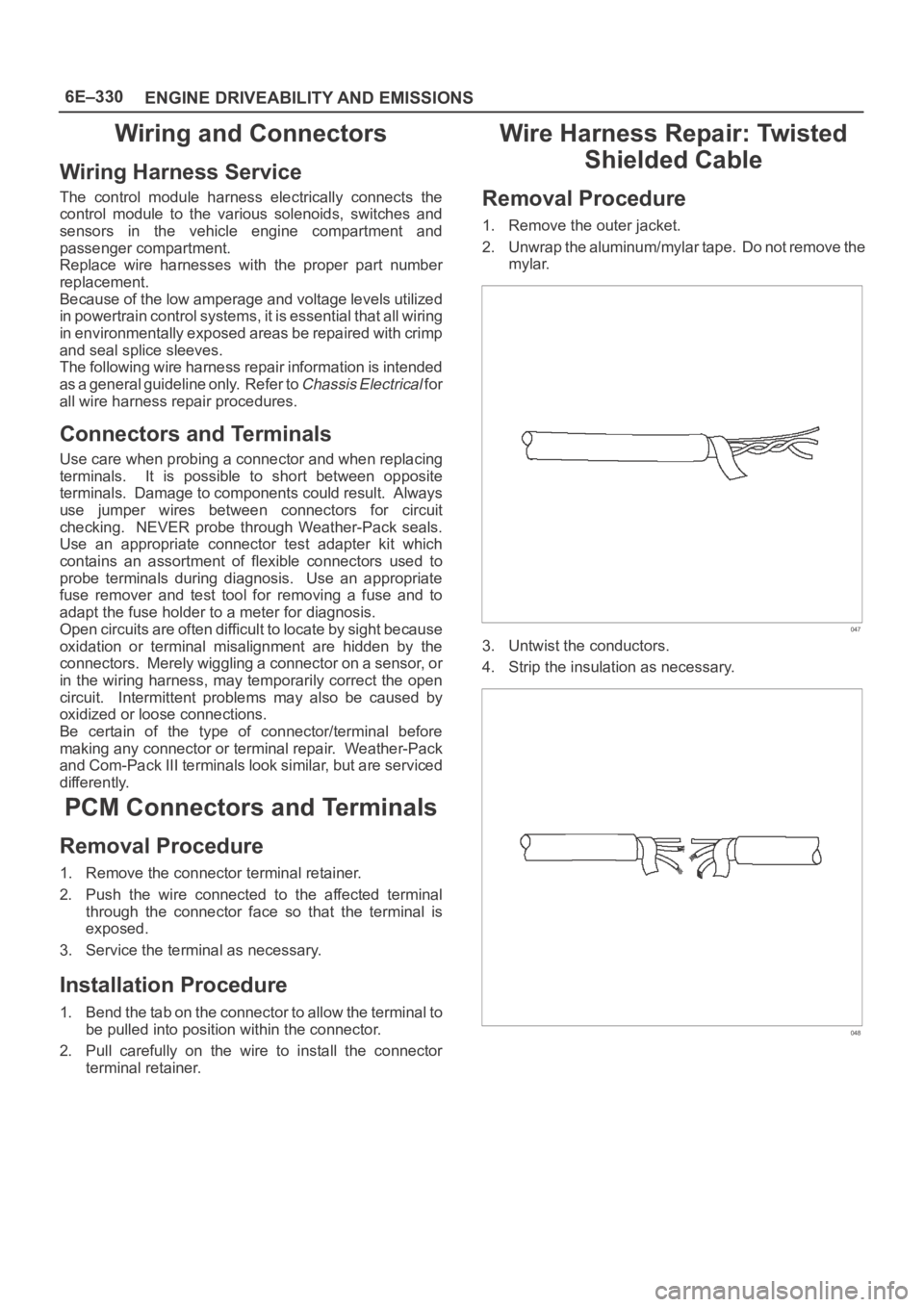
1. Remove the outer jacket.
2. Unwrap the aluminum/mylar tape. Do not remove the
mylar.
047
3. Untwist the conductors.
4. Strip the insulation as necessary.
048
Page 1451 of 6000

6E–334
ENGINE DRIVEABILITY AND EMISSIONS
Removal Procedure
S o m e c o n n e c t o r s u s e t e r m i n a l s c a l l e d M e t r i - P a c k S e r i e s
150. These may be used at the engine coolant
temperature (ECT) sensor.
1. Slide the seal (1) back on the wire.
2. Insert the J 35689 tool or equivalent (3) in order to
release the terminal locking tang (2).
060
3. Push the wire and the terminal out through the
connector. If you reuse the terminal, reshape the
locking tang.
Installation Procedure
Metri-Pack terminals are also referred to as “pull-to-seat”
terminals.
1. In order to install a terminal on a wire, the wire must be
inserted through the seal (2) and through the
connector (3).
2. The terminal (1) is then crimped onto the wire.
061
3. Then the terminal is pulled back into the connector to
seat it in place.