1998 OPEL FRONTERA sensor
[x] Cancel search: sensorPage 1793 of 6000
6A – 60 ENGINE MECHANICAL
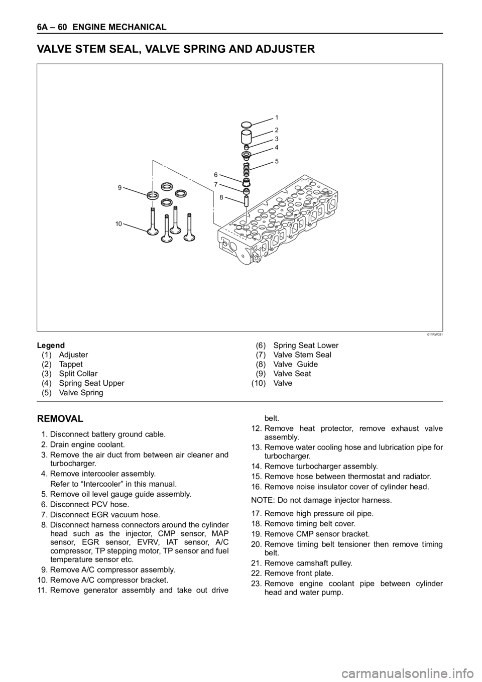
VALVE STEM SEAL, VALVE SPRING AND ADJUSTER
REMOVAL
1. Disconnect battery ground cable.
2. Drain engine coolant.
3. Remove the air duct from between air cleaner and
turbocharger.
4. Remove intercooler assembly.
Refer to “Intercooler” in this manual.
5. Remove oil level gauge guide assembly.
6. Disconnect PCV hose.
7. Disconnect EGR vacuum hose.
8. Disconnect harness connectors around the cylinder
head such as the injector, CMP sensor, MAP
sensor, EGR sensor, EVRV, IAT sensor, A/C
compressor, TP stepping motor, TP sensor and fuel
temperature sensor etc.
9. Remove A/C compressor assembly.
10. Remove A/C compressor bracket.
11. Remove generator assembly and take out drivebelt.
12. Remove heat protector, remove exhaust valve
assembly.
13. Remove water cooling hose and lubrication pipe for
turbocharger.
14. Remove turbocharger assembly.
15. Remove hose between thermostat and radiator.
16. Remove noise insulator cover of cylinder head.
NOTE: Do not damage injector harness.
17. Remove high pressure oil pipe.
18. Remove timing belt cover.
19. Remove CMP sensor bracket.
20. Remove timing belt tensioner then remove timing
belt.
21. Remove camshaft pulley.
22. Remove front plate.
23. Remove engine coolant pipe between cylinder
head and water pump.
1
2
3
4
5
6
9
10
7
8
011RW031
Legend
(1) Adjuster
(2) Tappet
(3) Split Collar
(4) Spring Seat Upper
(5) Valve Spring(6) Spring Seat Lower
(7) Valve Stem Seal
(8) Valve Guide
(9) Valve Seat
(10) Valve
Page 1794 of 6000
ENGINE MECHANICAL 6A – 61
24. Remove fuel pipe between fuel pump and intake
manifold.
25. Remove fuel return pipe from rear of cylinder head.
26. Remove intake manifold assembly.
27. Disconnect glow plug harness and remove glow
plug.
28. Remove cylinder head cover.
29. Remove injector harness connector.
30. Disconnect harness connector from oil pressure
sensor and oil temperature sensor on the oil rail.
31. Remove injector harness assembly.
32. Remove injector clamp.
33. Remove injector is fixed bolts.
34. Remove injector assembly.
35. Remove oil rail.
36. Remove camshaft carrier assembly with camshaft.
37. Remove cylinder head assembly.
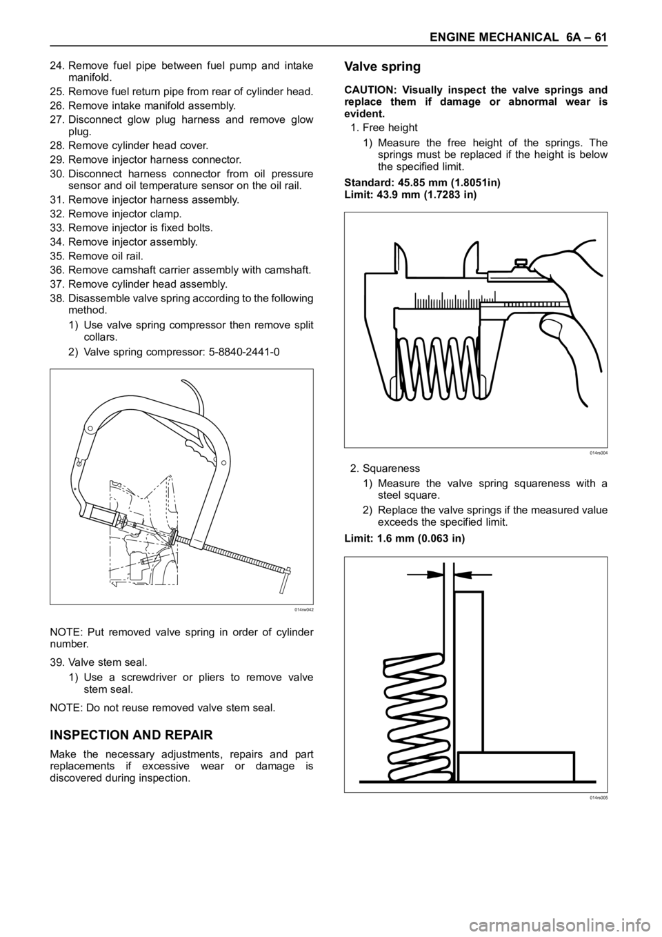
38. Disassemble valve spring according to the following
method.
1) Use valve spring compressor then remove split
collars.
2) Valve spring compressor: 5-8840-2441-0
NOTE: Put removed valve spring in order of cylinder
number.
39. Valve stem seal.
1) Use a screwdriver or pliers to remove valve
stem seal.
NOTE: Do not reuse removed valve stem seal.
INSPECTION AND REPAIR
Make the necessary adjustments, repairs and part
replacements if excessive wear or damage is
discovered during inspection.
Va l v e s p r i n g
CAUTION: Visually inspect the valve springs and
replace them if damage or abnormal wear is
evident.
1. Free height
1) Measure the free height of the springs. The
springs must be replaced if the height is below
the specified limit.
Standard: 45.85 mm (1.8051in)
Limit: 43.9 mm (1.7283 in)
2. Squareness
1) Measure the valve spring squareness with a
steel square.
2) Replace the valve springs if the measured value
exceeds the specified limit.
Limit: 1.6 mm (0.063 in)
014rw042
014rs004
014rs005
Page 1799 of 6000
6A – 66 ENGINE MECHANICAL
INSTALLATION
1. Valve stem seal
1) Use the special tool to install the stem seal to the
valve guide.
Stem Seal Installer: 5-8840-2033-0
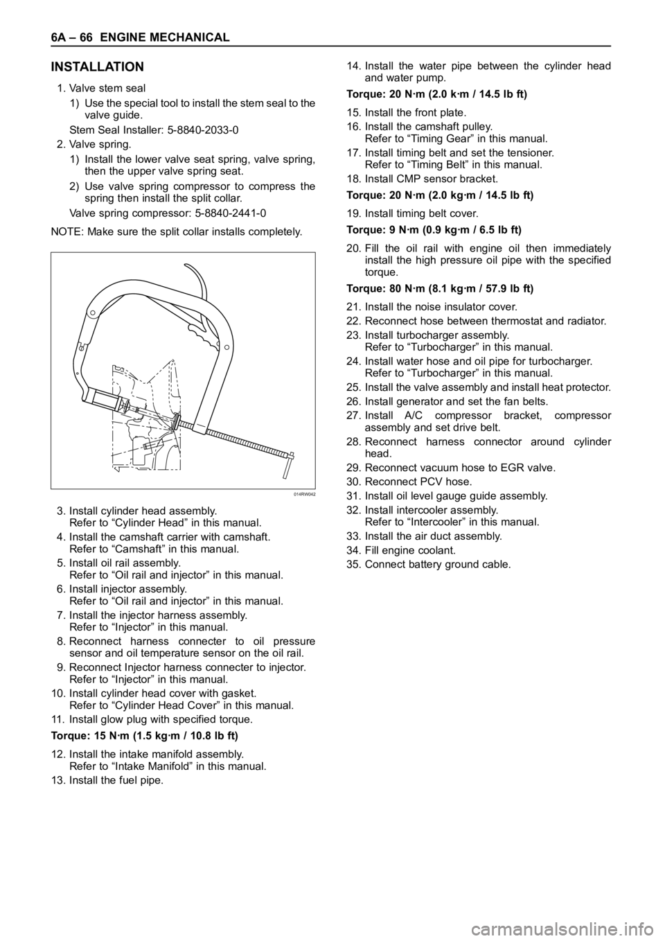
2. Valve spring.
1) Install the lower valve seat spring, valve spring,
then the upper valve spring seat.
2) Use valve spring compressor to compress the
spring then install the split collar.
Valve spring compressor: 5-8840-2441-0
NOTE: Make sure the split collar installs completely.
3. Install cylinder head assembly.
Refer to “Cylinder Head” in this manual.
4. Install the camshaft carrier with camshaft.
Refer to “Camshaft” in this manual.
5. Install oil rail assembly.
Refer to “Oil rail and injector” in this manual.
6. Install injector assembly.
Refer to “Oil rail and injector” in this manual.
7. Install the injector harness assembly.
Refer to “Injector” in this manual.
8. Reconnect harness connecter to oil pressure
sensor and oil temperature sensor on the oil rail.
9. Reconnect Injector harness connecter to injector.
Refer to “Injector” in this manual.
10. Install cylinder head cover with gasket.
Refer to “Cylinder Head Cover” in this manual.
11. Install glow plug with specified torque.
Torque: 15 Nꞏm (1.5 kgꞏm / 10.8 lb ft)
12. Install the intake manifold assembly.
Refer to “Intake Manifold” in this manual.
13. Install the fuel pipe.14. Install the water pipe between the cylinder head
and water pump.
Torque: 20 Nꞏm (2.0 kꞏm / 14.5 lb ft)
15. Install the front plate.
16. Install the camshaft pulley.
Refer to “Timing Gear” in this manual.
17. Install timing belt and set the tensioner.
Refer to “Timing Belt” in this manual.
18. Install CMP sensor bracket.
Torque: 20 Nꞏm (2.0 kgꞏm / 14.5 lb ft)
19. Install timing belt cover.
Torque: 9 Nꞏm (0.9 kgꞏm / 6.5 lb ft)
20. Fill the oil rail with engine oil then immediately
install the high pressure oil pipe with the specified
torque.
Torque: 80 Nꞏm (8.1 kgꞏm / 57.9 lb ft)
21. Install the noise insulator cover.
22. Reconnect hose between thermostat and radiator.
23. Install turbocharger assembly.
Refer to “Turbocharger” in this manual.
24. Install water hose and oil pipe for turbocharger.
Refer to “Turbocharger” in this manual.
25. Install the valve assembly and install heat protector.
26. Install generator and set the fan belts.
27. Install A/C compressor bracket, compressor
assembly and set drive belt.
28. Reconnect harness connector around cylinder
head.
29. Reconnect vacuum hose to EGR valve.
30. Reconnect PCV hose.
31. Install oil level gauge guide assembly.
32. Install intercooler assembly.
Refer to “Intercooler” in this manual.
33. Install the air duct assembly.
34. Fill engine coolant.
35. Connect battery ground cable.
014RW042
Page 1846 of 6000

ENGINE FUEL 6C – 1
ENGINE FUEL
CONTENTS
GENERAL DESCRIPTION
General Description . . . . . . . . . . . . . . . . . . 6C–1
On-Vehicle Service . . . . . . . . . . . . . . . . . . 6C–7
Fuel Filter Assembly . . . . . . . . . . . . . . . . 6C–7
Fuel Filter Cartridge . . . . . . . . . . . . . . . . 6C–7
Injector . . . . . . . . . . . . . . . . . . . . . . . . . . 6C–9
Fuel Pump Pipe . . . . . . . . . . . . . . . . . . . 6C–13High Pressure Oil Pump . . . . . . . . . . . . . 6C–15
Fuel Tank . . . . . . . . . . . . . . . . . . . . . . . . 6C–20
Fuel Gauge Unit . . . . . . . . . . . . . . . . . . . 6C–21
Fuel Filler Cap . . . . . . . . . . . . . . . . . . . . 6C–21
To realize the compatibility between low exhaust
emission and high engine output, an HEUI
(Hydraulically actuated Electronically controlled Unit
Injector) system, has been introduced. This system is
comprised of a hydraulic system, fuel system, and
electronic control system, using a high-pressure oil
pump in place of the conventional fuel injection pump.
The oil pressurized by means of this pump and by
signals from the ECM (Electronic Control Module)
actuates the fuel injector provided for each cylinder.
Inside of the fuel injector, fuel pressure is increased due
to the high-pressure oil. The ECM detects the driving
state of the vehicle, forms, signals sent by engine and
other part sensors, which determines the optimum fuel
injection amount and timing, thus controlling the fuel
injectors. Thus high engine output, good fuel economy,
and low exhaust emission are realized.When working on the fuel system, there are several
things to keep in mind:
1) Any time the fuel system is being worked on,
disconnect the negative battery cable except for
those tests where battery voltage is required.
2) Always keep a dry chemical (Class B) fire
extinguisher near the work area.
3) Replace all pipes with the same pipe and fittings
that were removed.
Clean and inspect “O” rings. Replace where
required.
4) Always relieve the line pressure before servicing
any fuel system components.
5) Do not attempt repairs on the fuel system until you
have read the instructions and checked the pictures
relating to that repair.
6) After maintenance work, push priming pump and
send enough fuel to the fuel system before starting
the engine.
NOTE: In comparison with the conventional engine,
the capacity of fuel passage in the 4JX1 engine is
larger. It takes the priming pump more time to fill the
engine with fuel.
Page 1860 of 6000
ENGINE FUEL 6C – 15
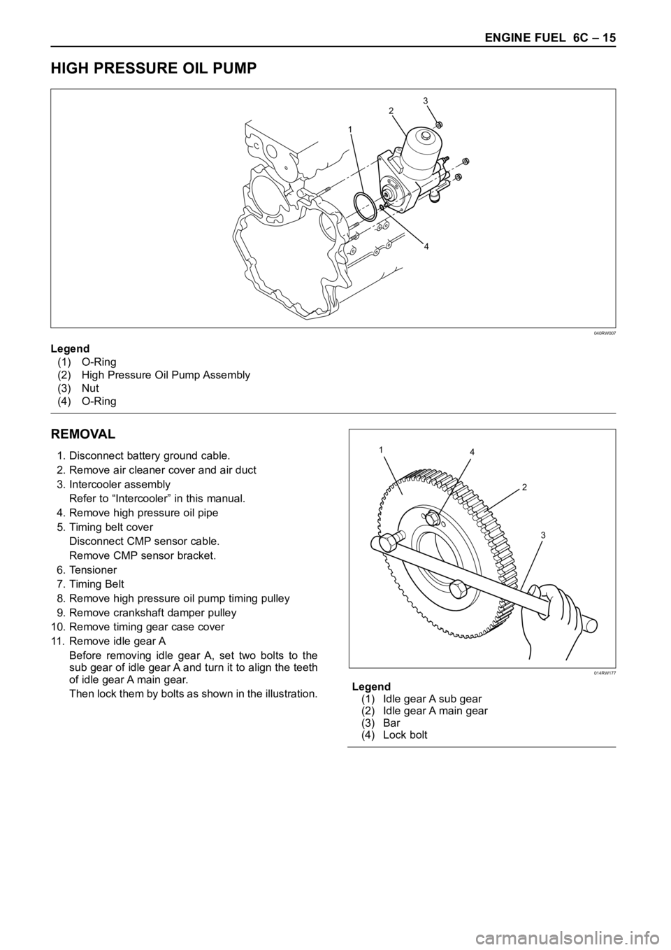
HIGH PRESSURE OIL PUMP
REMOVAL
1. Disconnect battery ground cable.
2. Remove air cleaner cover and air duct
3. Intercooler assembly
Refer to “Intercooler” in this manual.
4. Remove high pressure oil pipe
5. Timing belt cover
Disconnect CMP sensor cable.
Remove CMP sensor bracket.
6. Tensioner
7. Timing Belt
8. Remove high pressure oil pump timing pulley
9. Remove crankshaft damper pulley
10. Remove timing gear case cover
11. Remove idle gear A
Before removing idle gear A, set two bolts to the
sub gear of idle gear A and turn it to align the teeth
of idle gear A main gear.
Then lock them by bolts as shown in the illustration.Legend
(1) Idle gear A sub gear
(2) Idle gear A main gear
(3) Bar
(4) Lock bolt
1
2
43
Legend
(1) O-Ring
(2) High Pressure Oil Pump Assembly
(3) Nut
(4) O-Ring
040RW007
4 1
2
3
014RW177
Page 1863 of 6000
6C – 18 ENGINE FUEL
4. Remove lock bolt of idle gear A.
5. Install timing gear case cover.
Refer to “Timing gear” in this manual.
6. Install front plate.
Torque: 20 Nꞏm (2.0 kgꞏm/14.5 lb ft)
7. Install timing pulley of high pressure oil pump.
Torque: 10 Nꞏm (1.0 kgꞏm/7.2 lb ft)
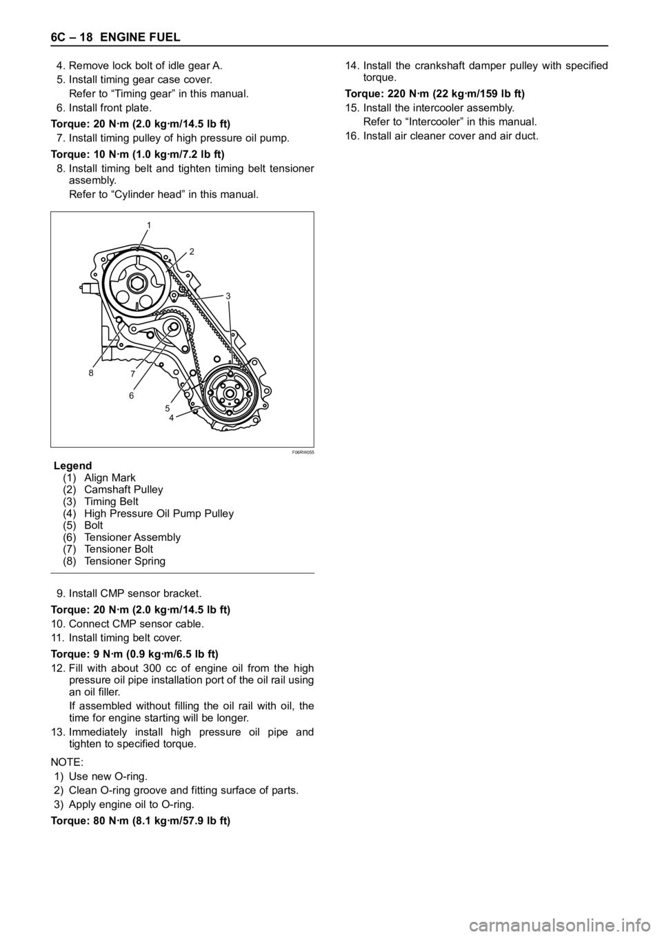
8. Install timing belt and tighten timing belt tensioner
assembly.
Refer to “Cylinder head” in this manual.
Legend
(1) Align Mark
(2) Camshaft Pulley
(3) Timing Belt
(4) High Pressure Oil Pump Pulley
(5) Bolt
(6) Tensioner Assembly
(7) Tensioner Bolt
(8) Tensioner Spring
9. Install CMP sensor bracket.
Torque: 20 Nꞏm (2.0 kgꞏm/14.5 lb ft)
10. Connect CMP sensor cable.
11. Install timing belt cover.
Torque: 9 Nꞏm (0.9 kgꞏm/6.5 lb ft)
12. Fill with about 300 cc of engine oil from the high
pressure oil pipe installation port of the oil rail using
an oil filler.
If assembled without filling the oil rail with oil, the
time for engine starting will be longer.
13. Immediately install high pressure oil pipe and
tighten to specified torque.
NOTE:
1) Use new O-ring.
2) Clean O-ring groove and fitting surface of parts.
3) Apply engine oil to O-ring.
Torque: 80 Nꞏm (8.1 kgꞏm/57.9 lb ft)14. Install the crankshaft damper pulley with specified
torque.
Torque: 220 Nꞏm (22 kgꞏm/159 lb ft)
15. Install the intercooler assembly.
Refer to “Intercooler” in this manual.
16. Install air cleaner cover and air duct.
1
2
3
8
67
4 5
F06RW055
Page 1890 of 6000
ENGINE ELECTRICAL 6D – 23
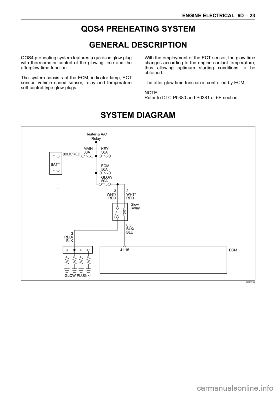
QOS4 PREHEATING SYSTEM
GENERAL DESCRIPTION
QOS4 preheating system features a quick-on glow plug
with thermometer control of the glowing time and the
afterglow time function.
The system consists of the ECM, indicator lamp, ECT
sensor, vehicle speed sensor, relay and temperature
self-control type glow plugs.With the employment of the ECT sensor, the glow time
changes according to the engine coolant temperature,
thus allowing optimum starting conditions to be
obtained.
The after glow time function is controlled by ECM.
NOTE:
Refer to DTC P0380 and P0381 of 6E section.
SYSTEM DIAGRAM
+
-KEY
50A
ECM
50A
GLOW
50A
2
WHT/
RED
0.5
BLK/
BLU
ECM J1-15 3
WHT/
RED
3
RED/
BLKMAIN
80A
8BLK/RED
Glow
Relay
GLOW PLUG 4
BATTHeater & A/C
Relay
060RW132
Page 1891 of 6000
6D – 24 ENGINE ELECTRICAL
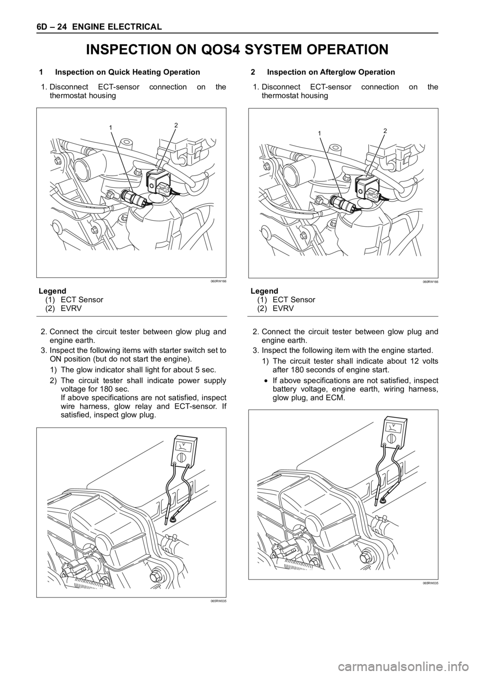
1 Inspection on Quick Heating Operation
1. Disconnect ECT-sensor connection on the
thermostat housing
Legend
(1) ECT Sensor
(2) EVRV
2. Connect the circuit tester between glow plug and
engine earth.
3. Inspect the following items with starter switch set to
ON position (but do not start the engine).
1) The glow indicator shall light for about 5 sec.
2) The circuit tester shall indicate power supply
voltage for 180 sec.
If above specifications are not satisfied, inspect
wire harness, glow relay and ECT-sensor. If
satisfied, inspect glow plug.2 Inspection on Afterglow Operation
1. Disconnect ECT-sensor connection on the
thermostat housing
Legend
(1) ECT Sensor
(2) EVRV
2. Connect the circuit tester between glow plug and
engine earth.
3. Inspect the following item with the engine started.
1) The circuit tester shall indicate about 12 volts
after 180 seconds of engine start.
If above specifications are not satisfied, inspect
battery voltage, engine earth, wiring harness,
glow plug, and ECM.
12
060RW166
065RW035
12
060RW166
065RW035
INSPECTION ON QOS4 SYSTEM OPERATION