Page 1861 of 6000
6C – 16 ENGINE FUEL
12. Remove high pressure oil pump
13. Remove high pressure oil pump assembly
Legend
(1) O-ring
(2) High pressure oil pump
(3) Nut
(4) O-ring
1
2
43
040RW007
Page 1862 of 6000
ENGINE FUEL 6C – 17
INSPECTION AND REPAIR
The high pressure oil pump is made precisely,
therefore, disassembly is not recommended.
INSTALLATION
1. Set O-ring to high pressure oil pump assembly.
Install the pump assembly into the rear of timing
gear case.
Tighten nut to specified torque.
Torque: 20 Nꞏm (2.0 kgꞏm/14.5 lb ft)
Legend
(1) O-ring
(2) High Pressure Oil Pump Assembly
(3) Nuts
(4) O-ring
2. Tighten high pressure oil pump assembly bracket
together with two way valve bracket.
Torque: 27 Nꞏm (2.8 kgꞏm/20.2 lb ft)Legend
(1) High Pressure Oil Pump Assembly
(2) Nut
(3) Two Way Valve Bracket
(4) Bolt
3. Install the pump gear to align timing mark with idle
gear A.
Tighten high pressure pump gear fixing bolt to the
specified torque.
Apply engine oil to thread and seat of bolt.
Torque: 75 Nꞏm (7.6 kgꞏm/55 lb ft)
Legend
(1) O-ring
(2) Pump Gear
(3) Bolt
(4) Timing Mark
1
2
43
040RW007
2
3
4 1
040RW006
4
GEAR:O/PUMP
IDLE GEAR A
1
2
3
040RW005
Page 1863 of 6000

6C – 18 ENGINE FUEL
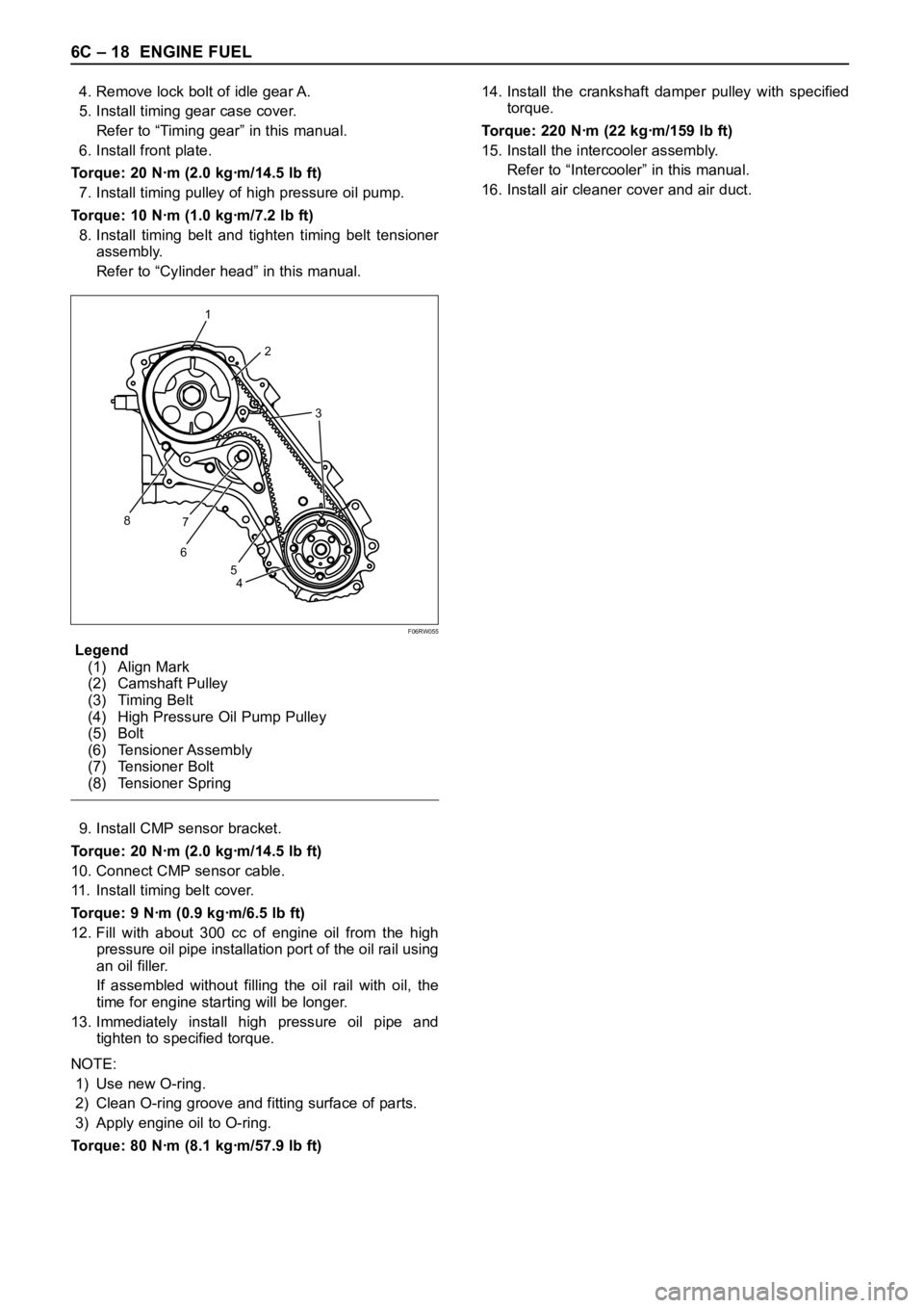
4. Remove lock bolt of idle gear A.
5. Install timing gear case cover.
Refer to “Timing gear” in this manual.
6. Install front plate.
Torque: 20 Nꞏm (2.0 kgꞏm/14.5 lb ft)
7. Install timing pulley of high pressure oil pump.
Torque: 10 Nꞏm (1.0 kgꞏm/7.2 lb ft)
8. Install timing belt and tighten timing belt tensioner
assembly.
Refer to “Cylinder head” in this manual.
Legend
(1) Align Mark
(2) Camshaft Pulley
(3) Timing Belt
(4) High Pressure Oil Pump Pulley
(5) Bolt
(6) Tensioner Assembly
(7) Tensioner Bolt
(8) Tensioner Spring
9. Install CMP sensor bracket.
Torque: 20 Nꞏm (2.0 kgꞏm/14.5 lb ft)
10. Connect CMP sensor cable.
11. Install timing belt cover.
Torque: 9 Nꞏm (0.9 kgꞏm/6.5 lb ft)
12. Fill with about 300 cc of engine oil from the high
pressure oil pipe installation port of the oil rail using
an oil filler.
If assembled without filling the oil rail with oil, the
time for engine starting will be longer.
13. Immediately install high pressure oil pipe and
tighten to specified torque.
NOTE:
1) Use new O-ring.
2) Clean O-ring groove and fitting surface of parts.
3) Apply engine oil to O-ring.
Torque: 80 Nꞏm (8.1 kgꞏm/57.9 lb ft)14. Install the crankshaft damper pulley with specified
torque.
Torque: 220 Nꞏm (22 kgꞏm/159 lb ft)
15. Install the intercooler assembly.
Refer to “Intercooler” in this manual.
16. Install air cleaner cover and air duct.
1
2
3
8
67
4 5
F06RW055
Page 1864 of 6000

ENGINE FUEL 6C – 19
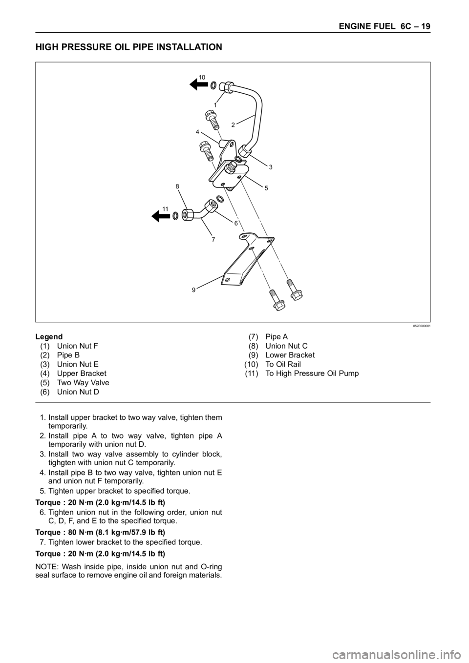
HIGH PRESSURE OIL PIPE INSTALLATION
1. Install upper bracket to two way valve, tighten them
temporarily.
2. Install pipe A to two way valve, tighten pipe A
temporarily with union nut D.
3. Install two way valve assembly to cylinder block,
tighgten with union nut C temporarily.
4. Install pipe B to two way valve, tighten union nut E
and union nut F temporarily.
5. Tighten upper bracket to specified torque.
Torque : 20 Nꞏm (2.0 kgꞏm/14.5 lb ft)
6. Tighten union nut in the following order, union nut
C, D, F, and E to the specified torque.
Torque : 80 Nꞏm (8.1 kgꞏm/57.9 lb ft)
7. Tighten lower bracket to the specified torque.
Torque : 20 Nꞏm (2.0 kgꞏm/14.5 lb ft)
NOTE: Wash inside pipe, inside union nut and O-ring
seal surface to remove engine oil and foreign materials.
6
5
7
9
8
114
1
2
3 10
Legend
(1) Union Nut F
(2) Pipe B
(3) Union Nut E
(4) Upper Bracket
(5) Two Way Valve
(6) Union Nut D(7) Pipe A
(8) Union Nut C
(9) Lower Bracket
(10) To Oil Rail
(11) To High Pressure Oil Pump
052R200001
Page 1879 of 6000
6D – 12 ENGINE ELECTRICAL
2) Inspect the brush springs for wear, damage or other
abnormal conditions.
Standard: 28 – 35 N (2.9 – 3.6 kg/6.4 – 7.9 lb)
Magnetic switch
1) Continuity of shunt coil
Check for continuity between terminals S and coil
case.
Replace, if there is not continuity (i.e., coil is
disconnected.)2) Continuity of series coil
Check for continuity between terminals S and M.
Replace, if there is no continuity (i.e., coil is
disconnected).
3) Continuity of contacts
With the plunger faced downward, push down the
magnetic switch. In this state, check for continuity
between terminals B and M. Replace, if there is no
continuity (i.e., contacts are faulty).
065RW052
065RW017
065RW018
065RW016
Page 1881 of 6000
6D – 14 ENGINE ELECTRICAL
MAGNETIC SWITCH
Pull-out test
Connect the magnetic switch to the battery as shown.
The negative side to the “M” terminal and the magnetic
switch body (housing); the positive side to the “S”
terminal. If the pinion has been ejected, the pull-in coil
is satisfactory.
Legend
(1) Terminal “S”
(2) Terminal “M”
(3) Starter
(4) For Return Test
(5) For Hold-In Test
Hold-in test
1. Next disconnect the “M” terminal.
2. The pinion should remain in the ejected position.
Return test
When the switch body is disconnected, the pinion
should return quickly.
2 1
5
3
4
065RW055
Page 1882 of 6000
ENGINE ELECTRICAL 6D – 15
CHARGING SYSTEM
GENERAL DESCRIPTION
GENERATOR
CHARGING CIRCUIT
The charging system is the IC integral regulator
charging system and its main components are
connected as shown in Figure.
The regulator is a solid state type and it is mounted
along with the brush holder assembly inside the
generator installed on the rear end cover.The generator does not require particular maintenance
such as voltage adjustment. The rectifier connected to
the stator coil has nine diodes to transform A.C. voltage
into D.C. voltage. This D.C. voltage is connected to the
output terminal of generator.
A06RW001
Condenser
GeneratorStator Coil
IC RegulatorStarter
SW
Rotor Coil
Battery
P F
EBS LRelay B
S
L
QOS
065R200028
Page 1883 of 6000
6D – 16 ENGINE ELECTRICAL
DIAGNOSIS
GENERAL ON-VEHICLE INSPECTION
The operating condition of the charging system is
indicated by the charge warning lamp. The warning
lamp comes on when the starter swtich is turned to
“ON” position. The charging system operates normallyif the lamp goes off when the engine starts. If the
warning lamp shows abnormality or if undercharged or
overcharged battery condition is suspected, perform
diagnosis by checking the charging system as follows:
Condenser
GeneratorStator Coil
IC RegulatorStarter
SW
Rotor Coil
Battery
P F
EBS LRelay B
S
L
QOS
065R200028
1. Check visually the belt and wiring connector.
2. With the engine in stop status, turn the starter
switch to “ON” position and observe the warning
lamp.
1) If lamp does not come on:
Disconnect wiring connector from generator,
and ground terminal “L” on connector side.
2) If lamp comes on:
Repair or replace the generator.