1998 OPEL FRONTERA engine oil
[x] Cancel search: engine oilPage 1885 of 6000
6D – 18 ENGINE ELECTRICAL
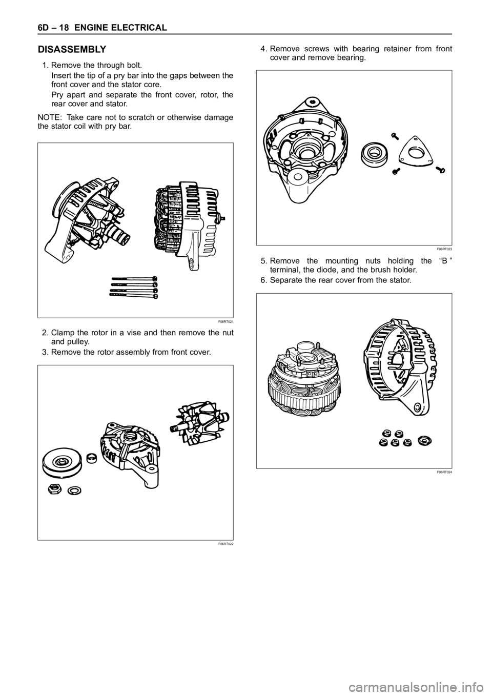
DISASSEMBLY
1. Remove the through bolt.
Insert the tip of a pry bar into the gaps between the
front cover and the stator core.
Pry apart and separate the front cover, rotor, the
rear cover and stator.
NOTE: Take care not to scratch or otherwise damage
the stator coil with pry bar.
2. Clamp the rotor in a vise and then remove the nut
and pulley.
3. Remove the rotor assembly from front cover.4. Remove screws with bearing retainer from front
cover and remove bearing.
5. Remove the mounting nuts holding the “B ”
terminal, the diode, and the brush holder.
6. Separate the rear cover from the stator.
F06RT021
F06RT022
F06RT023
F06RT024
Page 1887 of 6000
6D – 20 ENGINE ELECTRICAL
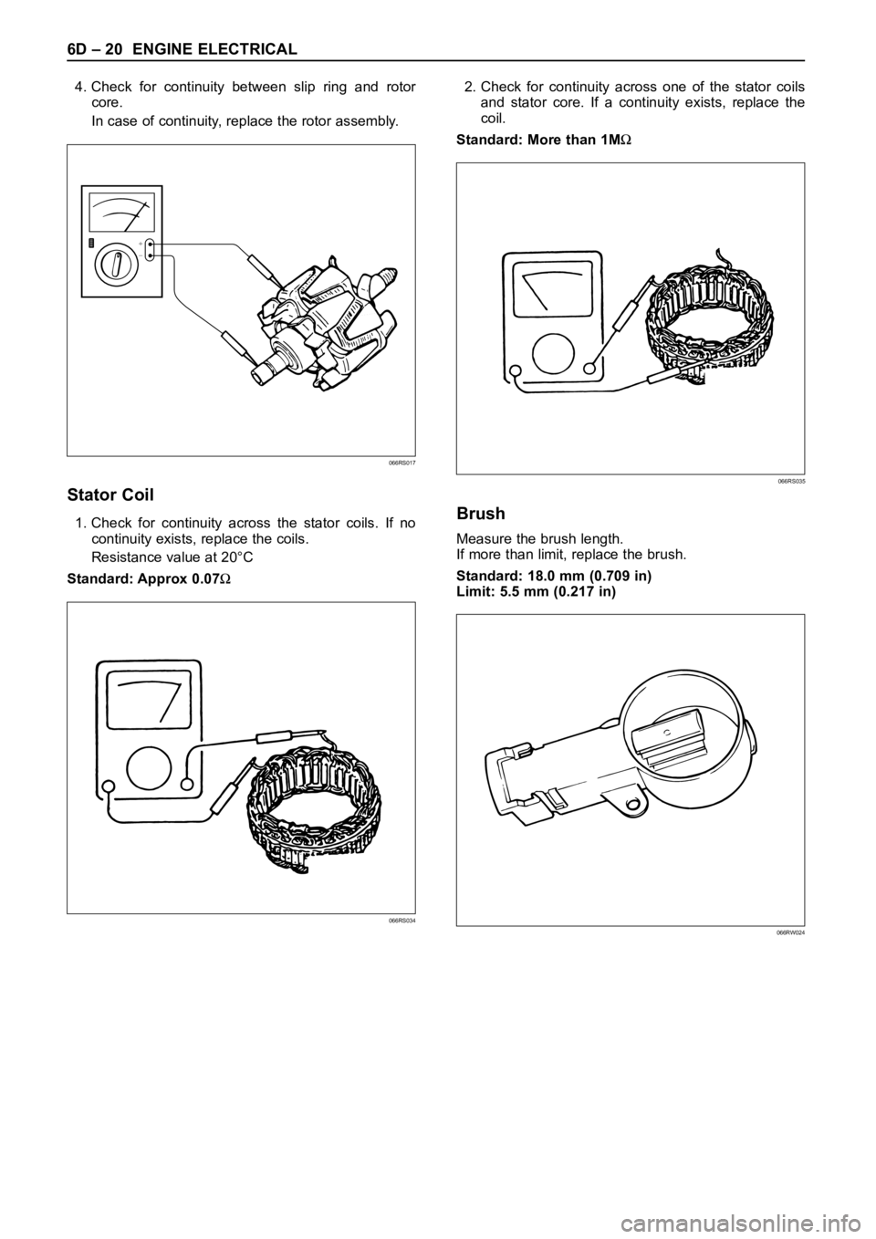
4. Check for continuity between slip ring and rotor
core.
In case of continuity, replace the rotor assembly.
Stator Coil
1. Check for continuity across the stator coils. If no
continuity exists, replace the coils.
Resistance value at 20°C
Standard: Approx 0.07
2. Check for continuity across one of the stator coils
and stator core. If a continuity exists, replace the
coil.
Standard: More than 1M
Brush
Measure the brush length.
If more than limit, replace the brush.
Standard: 18.0 mm (0.709 in)
Limit: 5.5 mm (0.217 in)
+
−
066RS017
066RS035
066RW024066RS034
Page 1888 of 6000
ENGINE ELECTRICAL 6D – 21
Rectifier Assembly
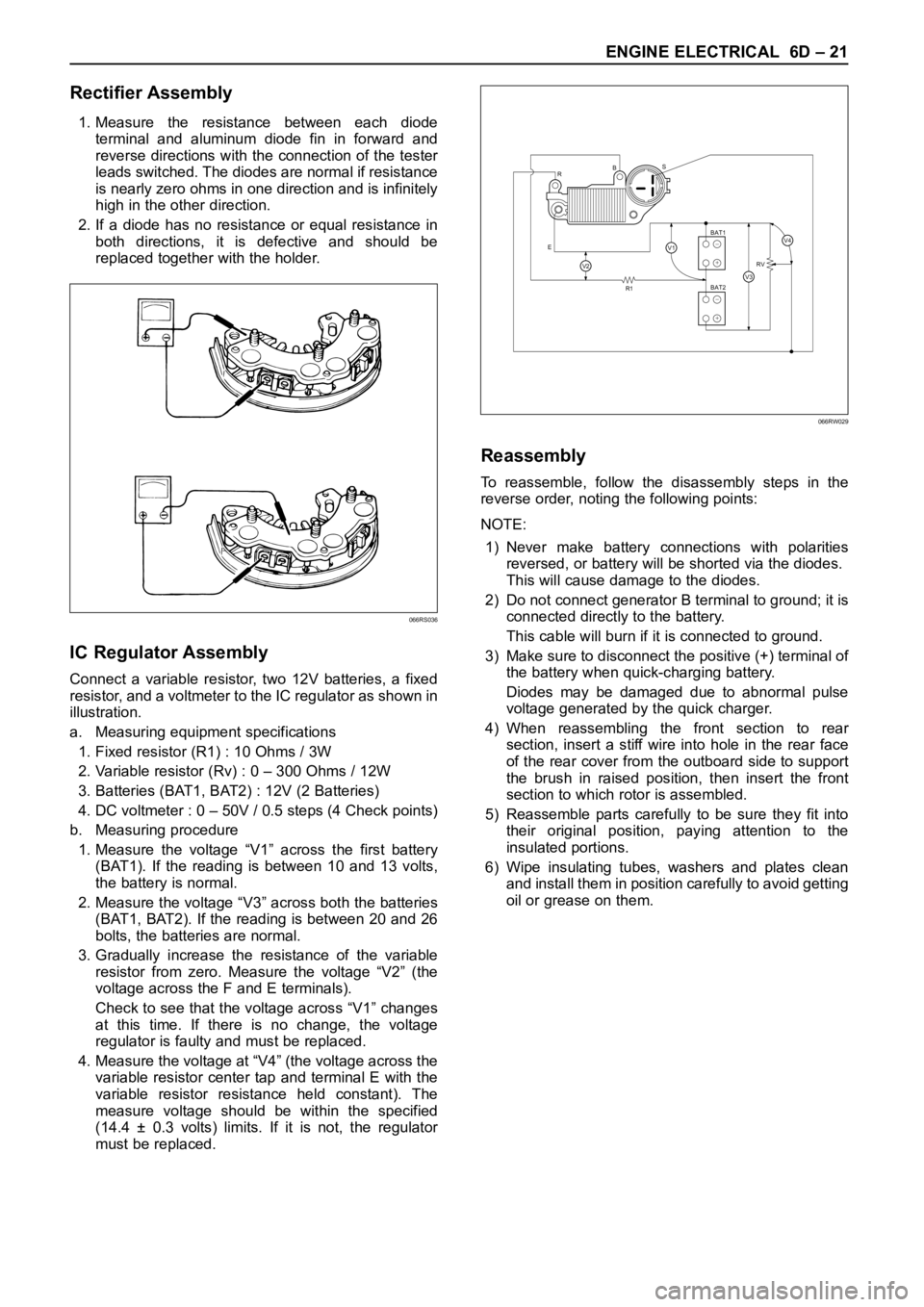
1. Measure the resistance between each diode
terminal and aluminum diode fin in forward and
reverse directions with the connection of the tester
leads switched. The diodes are normal if resistance
is nearly zero ohms in one direction and is infinitely
high in the other direction.
2. If a diode has no resistance or equal resistance in
both directions, it is defective and should be
replaced together with the holder.
IC Regulator Assembly
Connect a variable resistor, two 12V batteries, a fixed
resistor, and a voltmeter to the IC regulator as shown in
illustration.
a. Measuring equipment specifications
1. Fixed resistor (R1) : 10 Ohms / 3W
2. Variable resistor (Rv) : 0 – 300 Ohms / 12W
3. Batteries (BAT1, BAT2) : 12V (2 Batteries)
4. DC voltmeter : 0 – 50V / 0.5 steps (4 Check points)
b. Measuring procedure
1. Measure the voltage “V1” across the first battery
(BAT1). If the reading is between 10 and 13 volts,
the battery is normal.
2. Measure the voltage “V3” across both the batteries
(BAT1, BAT2). If the reading is between 20 and 26
bolts, the batteries are normal.
3. Gradually increase the resistance of the variable
resistor from zero. Measure the voltage “V2” (the
voltage across the F and E terminals).
Check to see that the voltage across “V1” changes
at this time. If there is no change, the voltage
regulator is faulty and must be replaced.
4. Measure the voltage at “V4” (the voltage across the
variable resistor center tap and terminal E with the
variable resistor resistance held constant). The
measure voltage should be within the specified
(14.4 ± 0.3 volts) limits. If it is not, the regulator
must be replaced.
Reassembly
To reassemble, follow the disassembly steps in the
reverse order, noting the following points:
NOTE:
1) Never make battery connections with polarities
reversed, or battery will be shorted via the diodes.
This will cause damage to the diodes.
2) Do not connect generator B terminal to ground; it is
connected directly to the battery.
This cable will burn if it is connected to ground.
3) Make sure to disconnect the positive (+) terminal of
the battery when quick-charging battery.
Diodes may be damaged due to abnormal pulse
voltage generated by the quick charger.
4) When reassembling the front section to rear
section, insert a stiff wire into hole in the rear face
of the rear cover from the outboard side to support
the brush in raised position, then insert the front
section to which rotor is assembled.
5) Reassemble parts carefully to be sure they fit into
their original position, paying attention to the
insulated portions.
6) Wipe insulating tubes, washers and plates clean
and install them in position carefully to avoid getting
oil or grease on them.
066RS036
R
EBS
R1RV
BAT2 BAT1
V2V3
V4V1+
−
+
−
066RW029
Page 1896 of 6000
6E–3 4JX1–TC ENGINE DRIVEABILITY AND EMISSIONS
Action Taken When the DTC Sets 6E–90. . . . . . .
Conditions for Clearing the MIL/DTC 6E–90. . . . .
Diagnostic Aids 6E–90. . . . . . . . . . . . . . . . . . . . . . . .
Diagnostic Trouble Code (DTC) P1196
(Flash DTC 62) Rail Pressure System
High Warning 6E–92. . . . . . . . . . . . . . . . . . . . . . . . . .
Circuit Description 6E–93. . . . . . . . . . . . . . . . . . . . .
Action Taken When the DTC Sets 6E–93. . . . . . .
Conditions for Clearing the MIL/DTC 6E–93. . . . .
Diagnostic Aids 6E–93. . . . . . . . . . . . . . . . . . . . . . . .
Test Description 6E–93. . . . . . . . . . . . . . . . . . . . . . .
Diagnostic Trouble Code (DTC) P0197
(Flash DTC 16) Oil Temp Sensor Low
Voltage 6E–94. . . . . . . . . . . . . . . . . . . . . . . . . . . . . . . .
Circuit Description 6E–94. . . . . . . . . . . . . . . . . . . . .
Action Taken When the DTC Sets 6E–94. . . . . . .
Conditions for Clearing the MIL/DTC 6E–94. . . . .
Diagnostic Aids 6E–94. . . . . . . . . . . . . . . . . . . . . . . .
Test Description 6E–95. . . . . . . . . . . . . . . . . . . . . . .
Engine Oil Temperature Sensor 6E–95. . . . . . . . .
Diagnostic Trouble Code (DTC) P0198
(Flash DTC 16) Oil Temp Sensor High
Voltage 6E–96. . . . . . . . . . . . . . . . . . . . . . . . . . . . . . . .
Circuit Description 6E–96. . . . . . . . . . . . . . . . . . . . .
Action Taken When the DTC Sets 6E–96. . . . . . .
Conditions for Clearing the MIL/DTC 6E–96. . . . .
Diagnostic Aids 6E–96. . . . . . . . . . . . . . . . . . . . . . . .
Test Description 6E–97. . . . . . . . . . . . . . . . . . . . . . .
Engine Oil Temperature Sensor 6E–97. . . . . . . . .
Diagnostic Trouble Code (DTC) P0201
(Flash DTC 51) Injector # 1 Circuit Fault 6E–99. . .
Circuit Description 6E–99. . . . . . . . . . . . . . . . . . . . .
Action Taken When the DTC Sets 6E–99. . . . . . .
Conditions for Clearing the MIL/DTC 6E–99. . . . .
Diagnostic Aids 6E–99. . . . . . . . . . . . . . . . . . . . . . . .
Test Description 6E–99. . . . . . . . . . . . . . . . . . . . . . .
Injector Test 6E–99. . . . . . . . . . . . . . . . . . . . . . . . . .
Diagnostic Trouble Code (DTC) P0202
(Flash DTC 52) Injector # 2 Circuit Fault 6E–101. . .
Circuit Description 6E–101. . . . . . . . . . . . . . . . . . . . .
Action Taken When the DTC Sets 6E–101. . . . . . .
Conditions for Clearing the MIL/DTC 6E–101. . . . .
Diagnostic Aids 6E–101. . . . . . . . . . . . . . . . . . . . . . . .
Test Description 6E–101. . . . . . . . . . . . . . . . . . . . . . .
Injector Test 6E–101. . . . . . . . . . . . . . . . . . . . . . . . . .
Diagnostic Trouble Code (DTC) P0203
(Flash DTC 52) Injector # 3 Circuit Fault 6E–103. . .
Circuit Description 6E–103. . . . . . . . . . . . . . . . . . . . .
Action Taken When the DTC Sets 6E–103. . . . . . .
Conditions for Clearing the MIL/DTC 6E–103. . . . .
Diagnostic Aids 6E–103. . . . . . . . . . . . . . . . . . . . . . . .
Test Description 6E–103. . . . . . . . . . . . . . . . . . . . . . .
Injector Test 6E–103. . . . . . . . . . . . . . . . . . . . . . . . . . Diagnostic Trouble Code (DTC) P0204
(Flash DTC 54) Injector # 4 Circuit Fault 6E–105
. . .
Circuit Description 6E–105. . . . . . . . . . . . . . . . . . . . .
Action Taken When the DTC Sets 6E–105. . . . . . .
Conditions for Clearing the MIL/DTC 6E–105. . . . .
Diagnostic Aids 6E–105. . . . . . . . . . . . . . . . . . . . . . . .
Test Description 6E–105. . . . . . . . . . . . . . . . . . . . . . .
Injector Test 6E–105. . . . . . . . . . . . . . . . . . . . . . . . . .
Diagnostic Trouble Code (DTC) P0217
(Flash DTC 22) High Coolant Temp Waring 6E–107
Circuit Description 6E–107. . . . . . . . . . . . . . . . . . . . .
Action Taken When the DTC Sets 6E–107. . . . . . .
Conditions for Clearing the MIL/DTC 6E–107. . . . .
Diagnostic Aids 6E–107. . . . . . . . . . . . . . . . . . . . . . . .
Test Description 6E–107. . . . . . . . . . . . . . . . . . . . . . .
Diagnostic Trouble Code (DTC) P1217
(Flash DTC 36) High Oil Temp Warning 6E–109. . . .
Circuit Description 6E–109. . . . . . . . . . . . . . . . . . . . .
Action Taken When the DTC Sets 6E–109. . . . . . .
Conditions for Clearing the MIL/DTC 6E–109. . . . .
Diagnostic Aids 6E–109. . . . . . . . . . . . . . . . . . . . . . . .
Diagnostic Trouble Code (DTC) P0219
(Flash DTC 11) Engine Over Speed Warning 6E–111
Circuit Description 6E–111. . . . . . . . . . . . . . . . . . . . .
Action Taken When the DTC Sets 6E–111. . . . . . .
Conditions for Clearing the MIL/DTC 6E–111. . . . .
Diagnostic Aids 6E–111. . . . . . . . . . . . . . . . . . . . . . . .
Diagnostic Trouble Code (DTC) P0336
(Flash DTC 43) CKP (Crank Position)
Sensor Out of Synchro 6E–114. . . . . . . . . . . . . . . . . .
Circuit Description 6E–114. . . . . . . . . . . . . . . . . . . . .
Action Taken When the DTC Sets 6E–114. . . . . . .
Conditions for Clearing the MIL/DTC 6E–114. . . . .
Diagnostic Aids 6E–114. . . . . . . . . . . . . . . . . . . . . . . .
Diagnostic Trouble Code (DTC) P0337
(Flash DTC 43) CKP (Crank Position)
Sensor No Signal 6E–116. . . . . . . . . . . . . . . . . . . . . . .
Circuit Description 6E–116. . . . . . . . . . . . . . . . . . . . .
Action Taken When the DTC Sets 6E–116. . . . . . .
Conditions for Clearing the MIL/DTC 6E–116. . . . .
Diagnostic Aids 6E–116. . . . . . . . . . . . . . . . . . . . . . . .
Diagnostic Trouble Code (DTC) P0341
(Flash DTC 41) CMP (Cam Position)
Sensor Out of Synchro 6E–119. . . . . . . . . . . . . . . . . .
Circuit Description 6E–119. . . . . . . . . . . . . . . . . . . . .
Action Taken When the DTC Sets 6E–119. . . . . . .
Conditions for Clearing the MIL/DTC 6E–119. . . . .
Diagnostic Aids 6E–119. . . . . . . . . . . . . . . . . . . . . . . .
Test Description 6E–119. . . . . . . . . . . . . . . . . . . . . . .
Diagnostic Trouble Code (DTC) P0342
(Flash DTC 41) CMP (Cam Position)
Sensor No Signal 6E–122. . . . . . . . . . . . . . . . . . . . . . .
Circuit Description 6E–122. . . . . . . . . . . . . . . . . . . . .
Action Taken When the DTC Sets 6E–122. . . . . . .
Conditions for Clearing the MIL/DTC 6E–122. . . . .
Page 1898 of 6000
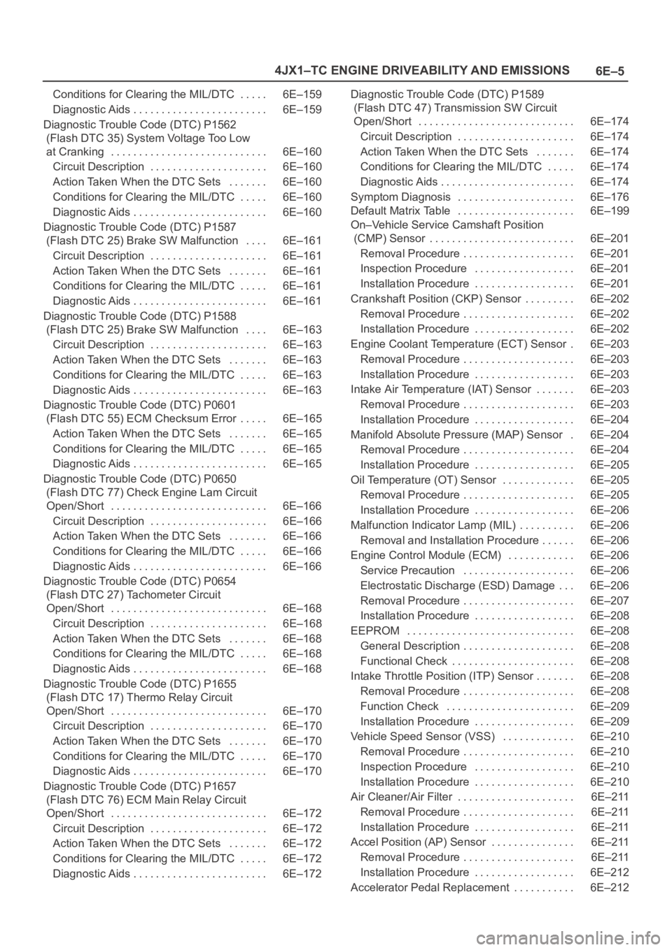
6E–5 4JX1–TC ENGINE DRIVEABILITY AND EMISSIONS
Conditions for Clearing the MIL/DTC 6E–159. . . . .
Diagnostic Aids 6E–159. . . . . . . . . . . . . . . . . . . . . . . .
Diagnostic Trouble Code (DTC) P1562
(Flash DTC 35) System Voltage Too Low
at Cranking 6E–160. . . . . . . . . . . . . . . . . . . . . . . . . . . .
Circuit Description 6E–160. . . . . . . . . . . . . . . . . . . . .
Action Taken When the DTC Sets 6E–160. . . . . . .
Conditions for Clearing the MIL/DTC 6E–160. . . . .
Diagnostic Aids 6E–160. . . . . . . . . . . . . . . . . . . . . . . .
Diagnostic Trouble Code (DTC) P1587
(Flash DTC 25) Brake SW Malfunction 6E–161. . . .
Circuit Description 6E–161. . . . . . . . . . . . . . . . . . . . .
Action Taken When the DTC Sets 6E–161. . . . . . .
Conditions for Clearing the MIL/DTC 6E–161. . . . .
Diagnostic Aids 6E–161. . . . . . . . . . . . . . . . . . . . . . . .
Diagnostic Trouble Code (DTC) P1588
(Flash DTC 25) Brake SW Malfunction 6E–163. . . .
Circuit Description 6E–163. . . . . . . . . . . . . . . . . . . . .
Action Taken When the DTC Sets 6E–163. . . . . . .
Conditions for Clearing the MIL/DTC 6E–163. . . . .
Diagnostic Aids 6E–163. . . . . . . . . . . . . . . . . . . . . . . .
Diagnostic Trouble Code (DTC) P0601
(Flash DTC 55) ECM Checksum Error 6E–165. . . . .
Action Taken When the DTC Sets 6E–165. . . . . . .
Conditions for Clearing the MIL/DTC 6E–165. . . . .
Diagnostic Aids 6E–165. . . . . . . . . . . . . . . . . . . . . . . .
Diagnostic Trouble Code (DTC) P0650
(Flash DTC 77) Check Engine Lam Circuit
Open/Short 6E–166. . . . . . . . . . . . . . . . . . . . . . . . . . . .
Circuit Description 6E–166. . . . . . . . . . . . . . . . . . . . .
Action Taken When the DTC Sets 6E–166. . . . . . .
Conditions for Clearing the MIL/DTC 6E–166. . . . .
Diagnostic Aids 6E–166. . . . . . . . . . . . . . . . . . . . . . . .
Diagnostic Trouble Code (DTC) P0654
(Flash DTC 27) Tachometer Circuit
Open/Short 6E–168. . . . . . . . . . . . . . . . . . . . . . . . . . . .
Circuit Description 6E–168. . . . . . . . . . . . . . . . . . . . .
Action Taken When the DTC Sets 6E–168. . . . . . .
Conditions for Clearing the MIL/DTC 6E–168. . . . .
Diagnostic Aids 6E–168. . . . . . . . . . . . . . . . . . . . . . . .
Diagnostic Trouble Code (DTC) P1655
(Flash DTC 17) Thermo Relay Circuit
Open/Short 6E–170. . . . . . . . . . . . . . . . . . . . . . . . . . . .
Circuit Description 6E–170. . . . . . . . . . . . . . . . . . . . .
Action Taken When the DTC Sets 6E–170. . . . . . .
Conditions for Clearing the MIL/DTC 6E–170. . . . .
Diagnostic Aids 6E–170. . . . . . . . . . . . . . . . . . . . . . . .
Diagnostic Trouble Code (DTC) P1657
(Flash DTC 76) ECM Main Relay Circuit
Open/Short 6E–172. . . . . . . . . . . . . . . . . . . . . . . . . . . .
Circuit Description 6E–172. . . . . . . . . . . . . . . . . . . . .
Action Taken When the DTC Sets 6E–172. . . . . . .
Conditions for Clearing the MIL/DTC 6E–172. . . . .
Diagnostic Aids 6E–172. . . . . . . . . . . . . . . . . . . . . . . . Diagnostic Trouble Code (DTC) P1589
(Flash DTC 47) Transmission SW Circuit
Open/Short 6E–174. . . . . . . . . . . . . . . . . . . . . . . . . . . .
Circuit Description 6E–174. . . . . . . . . . . . . . . . . . . . .
Action Taken When the DTC Sets 6E–174. . . . . . .
Conditions for Clearing the MIL/DTC 6E–174. . . . .
Diagnostic Aids 6E–174. . . . . . . . . . . . . . . . . . . . . . . .
Symptom Diagnosis 6E–176. . . . . . . . . . . . . . . . . . . . .
Default Matrix Table 6E–199. . . . . . . . . . . . . . . . . . . . .
On–Vehicle Service Camshaft Position
(CMP) Sensor 6E–201. . . . . . . . . . . . . . . . . . . . . . . . . .
Removal Procedure 6E–201. . . . . . . . . . . . . . . . . . . .
Inspection Procedure 6E–201. . . . . . . . . . . . . . . . . .
Installation Procedure 6E–201. . . . . . . . . . . . . . . . . .
Crankshaft Position (CKP) Sensor 6E–202. . . . . . . . .
Removal Procedure 6E–202. . . . . . . . . . . . . . . . . . . .
Installation Procedure 6E–202. . . . . . . . . . . . . . . . . .
Engine Coolant Temperature (ECT) Sensor 6E–203.
Removal Procedure 6E–203. . . . . . . . . . . . . . . . . . . .
Installation Procedure 6E–203. . . . . . . . . . . . . . . . . .
Intake Air Temperature (IAT) Sensor 6E–203. . . . . . .
Removal Procedure 6E–203. . . . . . . . . . . . . . . . . . . .
Installation Procedure 6E–204. . . . . . . . . . . . . . . . . .
Manifold Absolute Pressure (MAP) Sensor 6E–204.
Removal Procedure 6E–204. . . . . . . . . . . . . . . . . . . .
Installation Procedure 6E–205. . . . . . . . . . . . . . . . . .
Oil Temperature (OT) Sensor 6E–205. . . . . . . . . . . . .
Removal Procedure 6E–205. . . . . . . . . . . . . . . . . . . .
Installation Procedure 6E–206. . . . . . . . . . . . . . . . . .
Malfunction Indicator Lamp (MIL) 6E–206. . . . . . . . . .
Removal and Installation Procedure 6E–206. . . . . .
Engine Control Module (ECM) 6E–206. . . . . . . . . . . .
Service Precaution 6E–206. . . . . . . . . . . . . . . . . . . .
Electrostatic Discharge (ESD) Damage 6E–206. . .
Removal Procedure 6E–207. . . . . . . . . . . . . . . . . . . .
Installation Procedure 6E–208. . . . . . . . . . . . . . . . . .
EEPROM 6E–208. . . . . . . . . . . . . . . . . . . . . . . . . . . . . .
General Description 6E–208. . . . . . . . . . . . . . . . . . . .
Functional Check 6E–208. . . . . . . . . . . . . . . . . . . . . .
Intake Throttle Position (ITP) Sensor 6E–208. . . . . . .
Removal Procedure 6E–208. . . . . . . . . . . . . . . . . . . .
Function Check 6E–209. . . . . . . . . . . . . . . . . . . . . . .
Installation Procedure 6E–209. . . . . . . . . . . . . . . . . .
Vehicle Speed Sensor (VSS) 6E–210. . . . . . . . . . . . .
Removal Procedure 6E–210. . . . . . . . . . . . . . . . . . . .
Inspection Procedure 6E–210. . . . . . . . . . . . . . . . . .
Installation Procedure 6E–210. . . . . . . . . . . . . . . . . .
Air Cleaner/Air Filter 6E–211. . . . . . . . . . . . . . . . . . . . .
Removal Procedure 6E–211. . . . . . . . . . . . . . . . . . . .
Installation Procedure 6E–211. . . . . . . . . . . . . . . . . .
Accel Position (AP) Sensor 6E–211. . . . . . . . . . . . . . .
Removal Procedure 6E–211. . . . . . . . . . . . . . . . . . . .
Installation Procedure 6E–212. . . . . . . . . . . . . . . . . .
Accelerator Pedal Replacement 6E–212. . . . . . . . . . .
Page 1900 of 6000
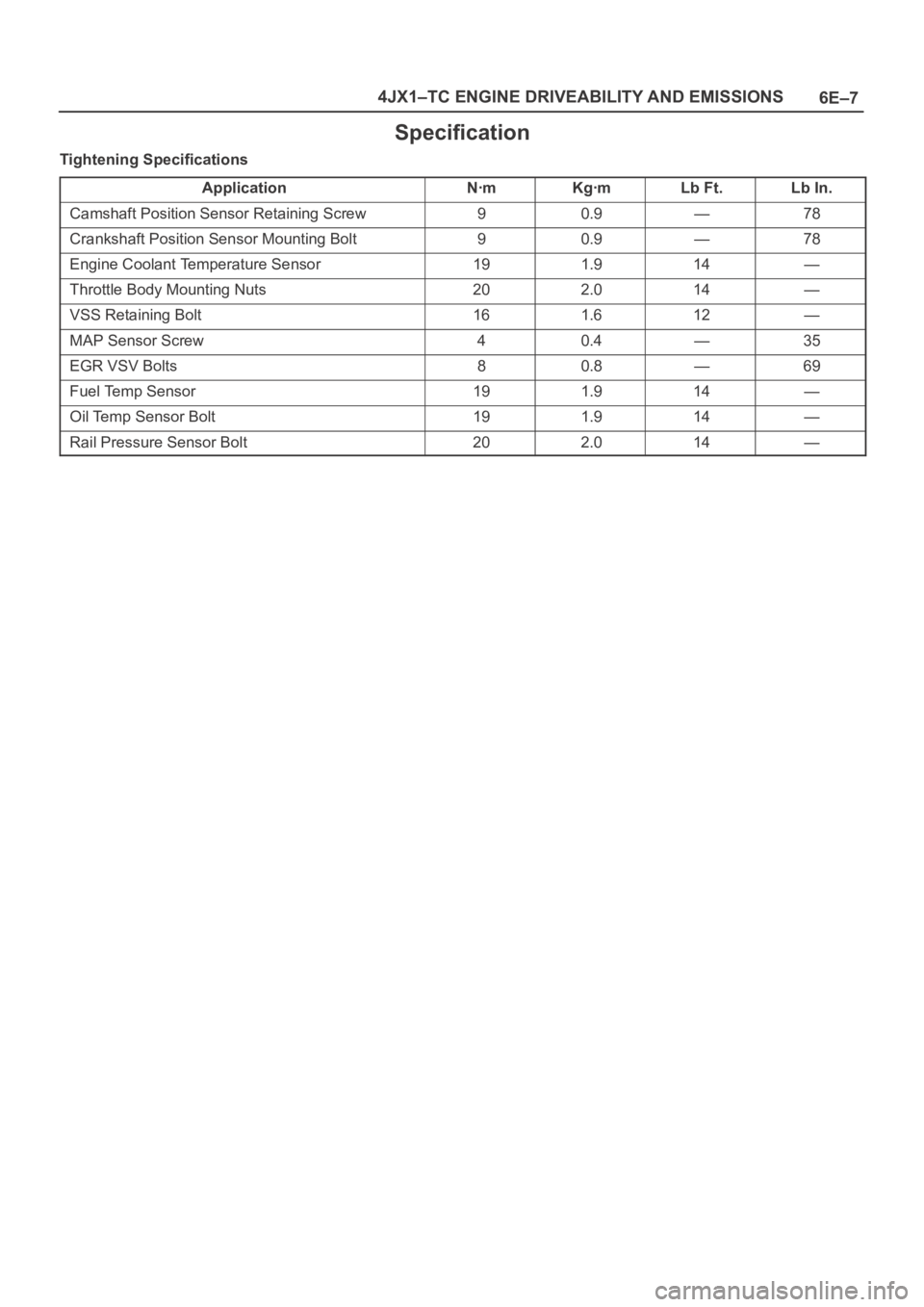
6E–7 4JX1–TC ENGINE DRIVEABILITY AND EMISSIONS
Specification
Tightening Specifications
Application
NꞏmKgꞏmLb Ft.Lb In.
Camshaft Position Sensor Retaining Screw90.9—78
Crankshaft Position Sensor Mounting Bolt90.9—78
Engine Coolant Temperature Sensor191.914—
Throttle Body Mounting Nuts202.014—
VSS Retaining Bolt161.612—
MAP Sensor Screw40.4—35
EGR VSV Bolts80.8—69
Fuel Temp Sensor191.914—
Oil Temp Sensor Bolt191.914—
Rail Pressure Sensor Bolt202.014—
Page 1909 of 6000
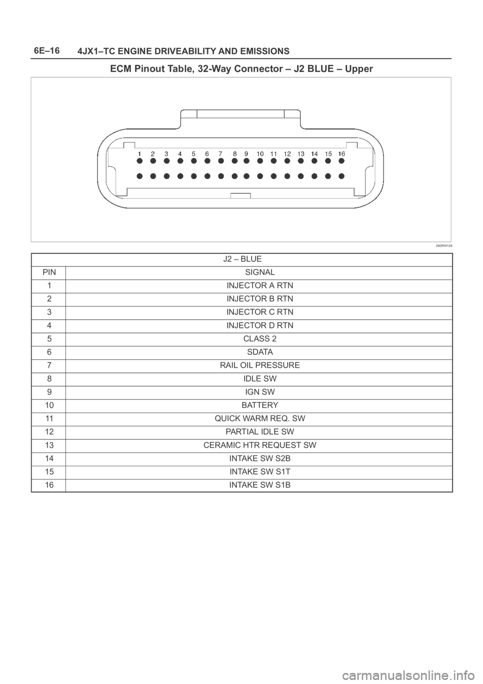
6E–16
4JX1–TC ENGINE DRIVEABILITY AND EMISSIONS
ECM Pinout Table, 32-Way Connector – J2 BLUE – Upper
060RW138
J2 – BLUE
PINSIGNAL
1INJECTOR A RTN
2INJECTOR B RTN
3INJECTOR C RTN
4INJECTOR D RTN
5CLASS 2
6SDATA
7RAIL OIL PRESSURE
8IDLE SW
9IGN SW
10BATTERY
11QUICK WARM REQ. SW
12PARTIAL IDLE SW
13CERAMIC HTR REQUEST SW
14INTAKE SW S2B
15INTAKE SW S1T
16INTAKE SW S1B
Page 1910 of 6000
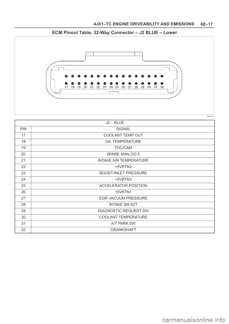
6E–17 4JX1–TC ENGINE DRIVEABILITY AND EMISSIONS
ECM Pinout Table, 32-Way Connector – J2 BLUE – Lower
060RW137
J2 – BLUE
PINSIGNAL
17COOLANT TEMP OUT
18OIL TEMPERATURE
19TDC/CAM
20SPARE ANALOG 2
21INTAKE AIR TEMPERATURE
22+5VRTN2
23BOOST/INLET PRESSURE
24+5VRTN3
25ACCELERATOR POSITION
26+5VRTN1
27EGR VACUUM PRESSURE
28INTAKE SM S2T
29DIAGNOSTIC REQUEST SW
30COOLANT TEMPERATURE
31A/T PARK SW
32CRANKSHAFT