1998 OPEL FRONTERA power steering
[x] Cancel search: power steeringPage 1456 of 6000
6E–339 ENGINE DRIVEABILITY AND EMISSIONS
0005
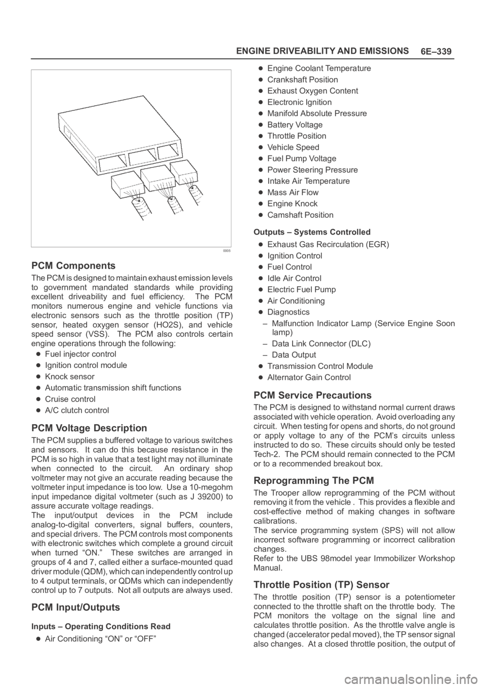
PCM Components
The PCM is designed to maintain exhaust emission levels
to government mandated standards while providing
excellent driveability and fuel efficiency. The PCM
monitors numerous engine and vehicle functions via
electronic sensors such as the throttle position (TP)
sensor, heated oxygen sensor (HO2S), and vehicle
speed sensor (VSS). The PCM also controls certain
engine operations through the following:
Fuel injector control
Ignition control module
Knock sensor
Automatic transmission shift functions
Cruise control
A/C clutch control
PCM Voltage Description
The PCM supplies a buffered voltage to various switches
and sensors. It can do this because resistance in the
PCM is so high in value that a test light may not illuminate
when connected to the circuit. An ordinary shop
voltmeter may not give an accurate reading because the
voltmeter input impedance is too low. Use a 10-megohm
input impedance digital voltmeter (such as J 39200) to
assure accurate voltage readings.
The input/output devices in the PCM include
analog-to-digital converters, signal buffers, counters,
and special drivers. The PCM controls most components
with electronic switches which complete a ground circuit
when turned “ON.” These switches are arranged in
groups of 4 and 7, called either a surface-mounted quad
driver module (QDM), which can independently control up
to 4 output terminals, or QDMs which can independently
control up to 7 outputs. Not all outputs are always used.
PCM Input/Outputs
Inputs – Operating Conditions Read
Air Conditioning “ON” or “OFF”
Engine Coolant Temperature
Crankshaft Position
Exhaust Oxygen Content
Electronic Ignition
Manifold Absolute Pressure
Battery Voltage
Throttle Position
Vehicle Speed
Fuel Pump Voltage
Power Steering Pressure
Intake Air Temperature
Mass Air Flow
Engine Knock
Camshaft Position
Outputs – Systems Controlled
Exhaust Gas Recirculation (EGR)
Ignition Control
Fuel Control
Idle Air Control
Electric Fuel Pump
Air Conditioning
Diagnostics
– Malfunction Indicator Lamp (Service Engine Soon
lamp)
– Data Link Connector (DLC)
– Data Output
Transmission Control Module
Alternator Gain Control
PCM Service Precautions
The PCM is designed to withstand normal current draws
associated with vehicle operation. Avoid overloading any
circuit. When testing for opens and shorts, do not ground
or apply voltage to any of the PCM’s circuits unless
instructed to do so. These circuits should only be tested
Tech-2. The PCM should remain connected to the PCM
or to a recommended breakout box.
Reprogramming The PCM
The Trooper allow reprogramming of the PCM without
removing it from the vehicle . This provides a flexible and
cost-effective method of making changes in software
calibrations.
The service programming system (SPS) will not allow
incorrect software programming or incorrect calibration
changes.
Refer to the UBS 98model year Immobilizer Workshop
Manual.
Throttle Position (TP) Sensor
The throttle position (TP) sensor is a potentiometer
connected to the throttle shaft on the throttle body. The
PCM monitors the voltage on the signal line and
calculates throttle position. As the throttle valve angle is
changed (accelerator pedal moved), the TP sensor signal
also changes. At a closed throttle position, the output of
Page 1785 of 6000
6A – 52 ENGINE MECHANICAL
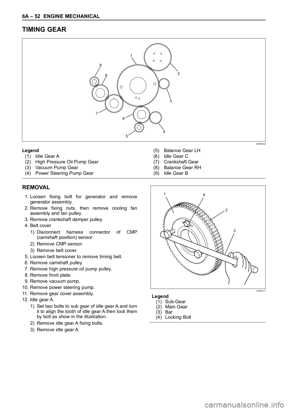
TIMING GEAR
REMOVAL
1. Loosen fixing bolt for generator and remove
generator assembly.
2. Remove fixing nuts, then remove cooling fan
assembly and fan pulley.
3. Remove crankshaft damper pulley.
4. Belt cover
1) Disconnect harness connector of CMP
(camshaft position) sensor.
2) Remove CMP sensor.
3) Remove belt cover.
5. Loosen belt tensioner to remove timing belt.
6. Remove camshaft pulley.
7. Remove high pressure oil pump pulley.
8. Remove front plate.
9. Remove vacuum pump.
10. Remove power steering pump.
11. Remove gear cover assembly.
12. Idle gear A.
1) Set two bolts to sub gear of idle gear A and turn
it to align the tooth of idle gear A then lock them
by bolt as show in the illustration.
2) Remove idle gear A fixing bolts.
3) Remove idle gear A.Legend
(1) Sub-Gear
(2) Main Gear
(3) Bar
(4) Locking Bolt
2
3
4
5 8
7
6 91
020RW028
Legend
(1) Idle Gear A
(2) High Pressure Oil Pump Gear
(3) Vacuum Pump Gear
(4) Power Steering Pump Gear(5) Balance Gear LH
(6) Idle Gear C
(7) Crankshaft Gear
(8) Balance Gear RH
(9) Idle Gear B
4 1
2
3
014RW177
Page 1790 of 6000
ENGINE MECHANICAL 6A – 57
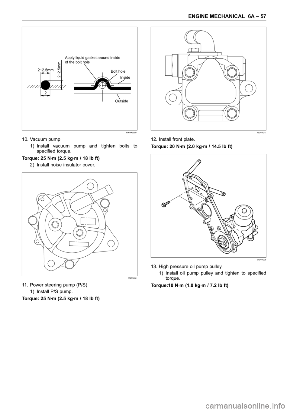
10. Vacuum pump
1) Install vacuum pump and tighten bolts to
specified torque.
Torque: 25 Nꞏm (2.5 kgꞏm / 18 lb ft)
2) Install noise insulator cover.
11. Power steering pump (P/S)
1) Install P/S pump.
Torque: 25 Nꞏm (2.5 kgꞏm / 18 lb ft)12. Install front plate.
Torque: 20 Nꞏm (2.0 kgꞏm / 14.5 lb ft)
13. High pressure oil pump pulley.
1) Install oil pump pulley and tighten to specified
torque.
Torque:10 Nꞏm (1.0 kgꞏm / 7.2 lb ft)
2
2~2.5mm
2~2.5mm
Apply liquid gasket around inside
of the bolt hole
Bolt hole
Inside
Outside
F06HX00001
052RW001
430RW017
012RW035
Page 2569 of 6000
8A–30LIGHTING SYSTEM
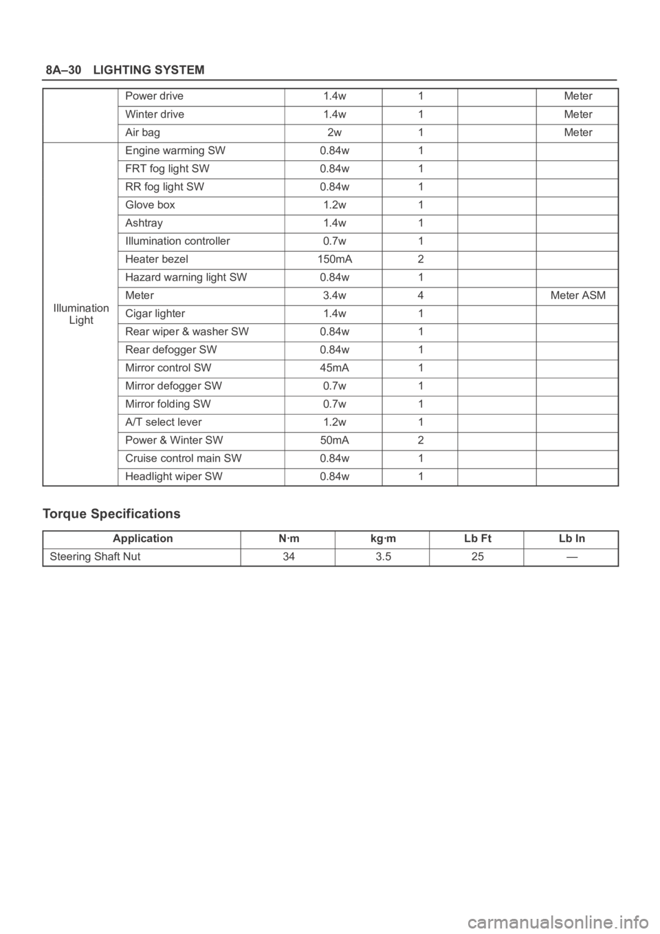
Power drive1.4w1Meter
Winter drive1.4w1Meter
Air bag2w1Meter
Engine warming SW0.84w1
FRT fog light SW0.84w1
RR fog light SW0.84w1
Glove box1.2w1
Ashtray1.4w1
Illumination controller0.7w1
Heater bezel150mA2
Hazard warning light SW0.84w1
Meter3.4w4Meter ASM
IlluminationCigar lighter1.4w1Light
Rear wiper & washer SW0.84w1
Rear defogger SW0.84w1
Mirror control SW45mA1
Mirror defogger SW0.7w1
Mirror folding SW0.7w1
A/T select lever1.2w1
Power & Winter SW50mA2
Cruise control main SW0.84w1
Headlight wiper SW0.84w1
Torque Specifications
ApplicationNꞏmkgꞏmLb FtLb In
Steering Shaft Nut343.525—
Page 2675 of 6000
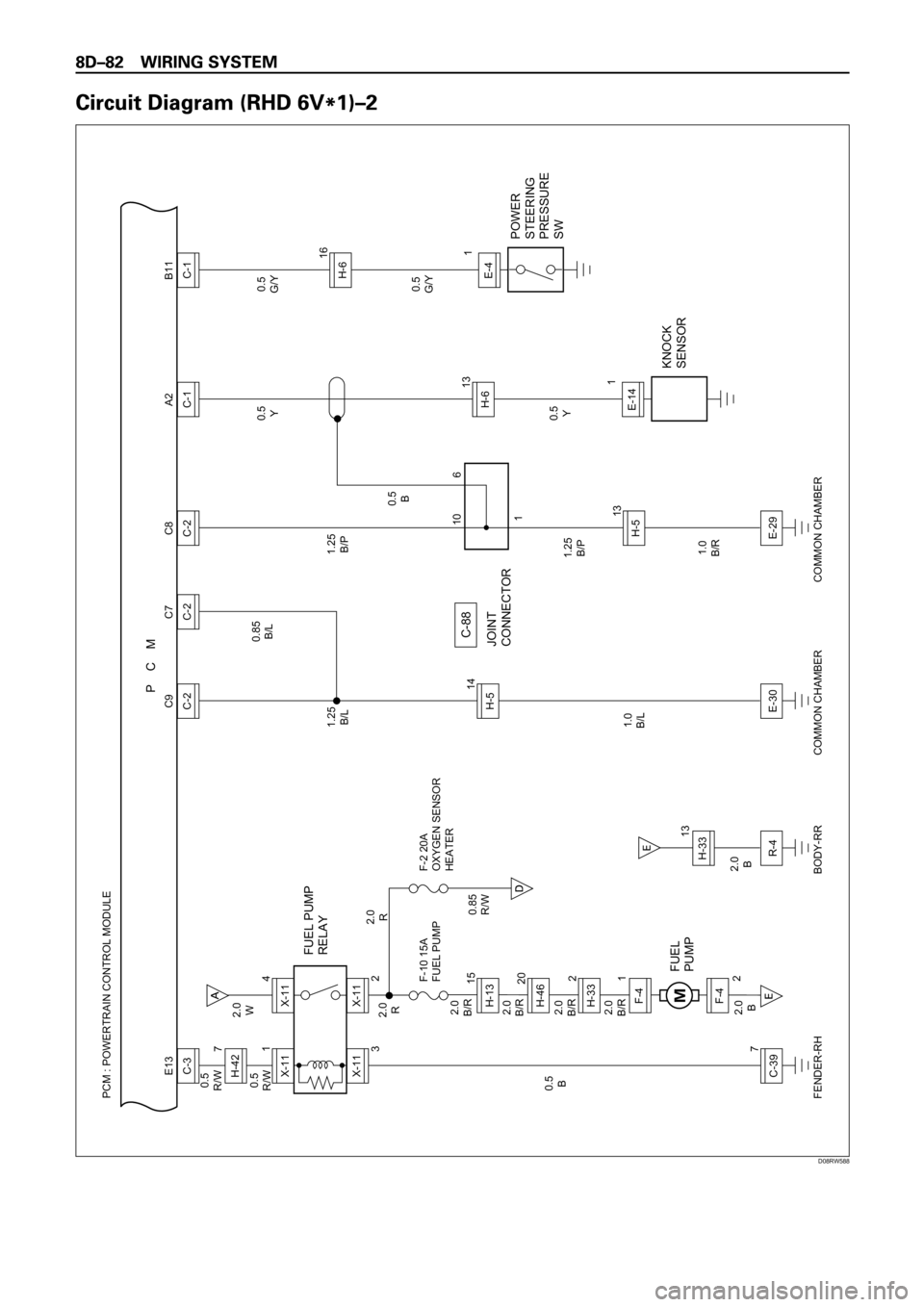
PCM : POWERTRAIN CONTROL MODULE
P C M
0.5
B
1.0
B/L 0.5
R/W
0.5
R/WX-111C-397 7
3X-11C-3 E13
FUEL PUMP
RELAY
FUEL
PUMP
F-10 15A
FUEL PUMPF-2 20A
OXYGEN SENSOR
HEATER
JOINT
CONNECTOR
KNOCK
SENSOR
2.0
B2.0
B 2.0
B/R2.0
B/R2.0
B/R2.0
B/R 2.0
R2.0
R1.25
B/L0.85
B/L
0.85
R/W
FENDER-RH2.0
WF-4
2H-4620H-332H-1315X-114
2X-11
1F-4
H-5
C-88
1410
16
E-30C-2C9
C-2C7
COMMON CHAMBER
R-4
BODY-RR
1.25
B/P
1.0
B/R1.25
B/P
0.5
B0.5
Y
0.5
Y
H-513E-29C-2C8
COMMON CHAMBER
H-613
1C-1E-14A2
POWER
STEERING
PRESSURE
SW
0.5
G/Y
0.5
G/YH-616
1C-1E-4 B11
H-42
13
H-33
D08RW588
Page 2690 of 6000
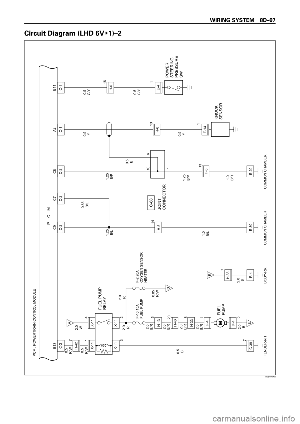
PCM : POWERTRAIN CONTROL MODULE
P C M
0.5
B
1.0
B/L 0.5
R/W
0.5
R/WX-111C-397 7
3X-11C-3 E13
FUEL PUMP
RELAY
FUEL
PUMP
F-10 15A
FUEL PUMPF-2 20A
OXYGEN SENSOR
HEATER
JOINT
CONNECTOR
KNOCK
SENSOR
2.0
B2.0
B 2.0
B/R2.0
B/R2.0
B/R2.0
B/R 2.0
R2.0
R1.25
B/L0.85
B/L
0.85
R/W
FENDER-RH2.0
WF-4
2H-4620H-338H-135X-114
2X-11
1F-4
H-5
C-88
1410
16
E-30C-2C9
C-2C7
COMMON CHAMBER
R-4
BODY-RR
1.25
B/P
1.0
B/R1.25
B/P
0.5
B0.5
Y
0.5
Y
H-513E-29C-2C8
COMMON CHAMBER
H-613
1C-1E-14A2
POWER
STEERING
PRESSURE
SW
0.5
G/Y
0.5
G/YH-616
1C-1E-4 B11
H-42
7
H-33
D08RW902
Page 3444 of 6000
SUPPLEMENTAL RESTRAINT SYSTEM9J–7
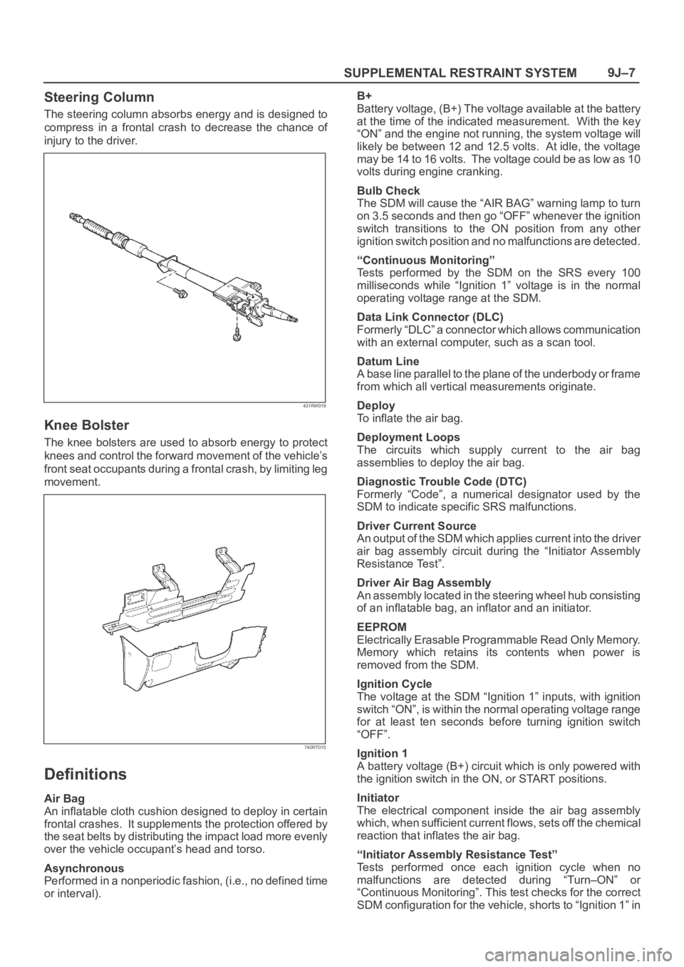
Steering Column
The steering column absorbs energy and is designed to
compress in a frontal crash to decrease the chance of
injury to the driver.
431RW019
Knee Bolster
The knee bolsters are used to absorb energy to protect
knees and control the forward movement of the vehicle’s
front seat occupants during a frontal crash, by limiting leg
movement.
740RT015
Definitions
Air Bag
An inflatable cloth cushion designed to deploy in certain
frontal crashes. It supplements the protection offered by
the seat belts by distributing the impact load more evenly
over the vehicle occupant’s head and torso.
Asynchronous
Performed in a nonperiodic fashion, (i.e., no defined time
or interval).B+
Battery voltage, (B+) The voltage available at the battery
at the time of the indicated measurement. With the key
“ON” and the engine not running, the system voltage will
likely be between 12 and 12.5 volts. At idle, the voltage
may be 14 to 16 volts. The voltage could be as low as 10
volts during engine cranking.
Bulb Check
The SDM will cause the “AIR BAG” warning lamp to turn
on 3.5 seconds and then go “OFF” whenever the ignition
switch transitions to the ON position from any other
ignition switch position and no malfunctions are detected.
“Continuous Monitoring”
Tests performed by the SDM on the SRS every 100
milliseconds while “Ignition 1” voltage is in the normal
operating voltage range at the SDM.
Data Link Connector (DLC)
Formerly “DLC” a connector which allows communication
with an external computer, such as a scan tool.
Datum Line
A base line parallel to the plane of the underbody or frame
from which all vertical measurements originate.
Deploy
To inflate the air bag.
Deployment Loops
The circuits which supply current to the air bag
assemblies to deploy the air bag.
Diagnostic Trouble Code (DTC)
Formerly “Code”, a numerical designator used by the
SDM to indicate specific SRS malfunctions.
Driver Current Source
An output of the SDM which applies current into the driver
air bag assembly circuit during the “Initiator Assembly
Resistance Test”.
Driver Air Bag Assembly
An assembly located in the steering wheel hub consisting
of an inflatable bag, an inflator and an initiator.
EEPROM
Electrically Erasable Programmable Read Only Memory.
Memory which retains its contents when power is
removed from the SDM.
Ignition Cycle
The voltage at the SDM “Ignition 1” inputs, with ignition
switch “ON”, is within the normal operating voltage range
for at least ten seconds before turning ignition switch
“OFF”.
Ignition 1
A battery voltage (B+) circuit which is only powered with
the ignition switch in the ON, or START positions.
Initiator
The electrical component inside the air bag assembly
which, when sufficient current flows, sets off the chemical
reaction that inflates the air bag.
“Initiator Assembly Resistance Test”
Tests performed once each ignition cycle when no
malfunctions are detected during “Turn–ON” or
“Continuous Monitoring”. This test checks for the correct
SDM configuration for the vehicle, shorts to “Ignition 1” in
Page 3445 of 6000
SUPPLEMENTAL RESTRAINT SYSTEM 9J–8
the deployment loops, high resistance or opens in the
“Driver Side High”, “Driver Side Low”, “Passenger Side
High” and “Passenger Side Low” circuits and measures
the resistance of the inflator assembly consisting of 1)
Initiators, 2) SRS coil assembly (driver side only), 3)
Connectors and associated wiring.
Normal Operating Voltage Range
The voltage measured between the SDM “Ignition 1”
terminals and “Ground” terminals is between 9 and 16
volts.
Passenger Current Source
An output of the SDM which applies current into the
passenger air bag assembly circuit during the “Initiator
Assembly Resistance Test”.
Passenger Air Bag Assembly
An assembly located in the right side of the instrument
panel consisting of an inflatable bag, an inflator and an
initiator.
Scan Tool
An external computer used to read diagnostic information
from on–board computers via the data link connector.
SDM
Sensing and Diagnostic Module which provides reserve
energy to the deployment loops, deploys the air bags
when required and performs diagnostic monitoring of all
SRS components.
Serial Data
Information representing the status of the SRS.
SRS
Supplemental Restraint System.
SRS Coil Assembly
An assembly of two current–carrying coils in the driver
deployment loop that allows the rotation of the steering
wheel while maintaining the continuous contact of the
driver deployment loop to the driver air bag assembly.
SRS Wiring Harness
The wires and connectors that electrically connect the
components in the SRS.
“Turn–ON”
Test which the SDM performs on the SRS once during
each ignition cycle immediately after “Ignition 1” voltage
is applied to the SDM and before “Continuous
Monitoring”.
Diagnosis
WARNING: TO AVOID DEPLOYMENT WHEN
TROUBLESHOOTING THE SRS, DO NOT USE
ELECTRICAL TEST EQUIPMENT SUCH AS A
BATTERY–POWERED OR AC–POWERED
VOLTMETER, OHMMETER, ETC., OR ANY TYPE OF
ELECTRICAL EQUIPMENT OTHER THAN THAT
SPECIFIED IN THIS MANUAL. DO NOT USE A
NONPOWERED PROBE–TYPE TESTER.
INSTRUCTIONS IN THIS MANUAL MUST BE
FOLLOWED CAREFULLY, OTHERWISE PERSONAL
INJURY MAY RESULT.
Diagnostic Trouble Codes
The “SRS Diagnostic System Check” must always be the
starting point of any SRS diagnosis. The “SRS
Diagnostic System Check” checks for proper “AIR BAG”
warning lamp operation and checks for SRS diagnostic
trouble codes using the scan tool.
1. Current diagnostic trouble codes – Malfunctions that
are presently being detected. Current diagnostic
trouble codes are stored in RAM (Random Access
Memory).
2. History diagnostic trouble codes – All malfunctions
detected since the last time the history memory was
cleared. History diagnostic trouble codes are stored
in EEPROM.
Scan Tool Diagnostics
A scan tool is used to read current and history diagnostic
trouble codes and to clear all diagnostic trouble codes
after a repair is completed. The scan tool must be
updated to communicate with the SRS through a
replaceable cartridge before it can be used for SRS
diagnostics. To use the scan tool, connect it to the data
link connector and turn the ignition switch “ON”. The scan
tool reads serial data from the SDM “Serial Data” line
terminal “24” to the data link connector terminal “9”.
Use Of Special Tools
WARNING: TO AV O I D D E P L O Y M E N T W H E N
TROUBLESHOOTING THE SRS, DO NOT USE
ELECTRICAL TEST EQUIPMENT SUCH AS A
BATTERY–POWERED OR AC–POWERED
VOLTMETER, OHMMETER, ETC, OR ANY TYPE OF
ELECTRICAL EQUIPMENT OTHER THAN THAT
SPECIFIED IN THIS MANUAL. DO NOT USE A NON
POWERED PROBE–TYPE TESTER. INSTRUCTIONS
IN THIS MANUAL MUST BE FOLLOWED
CAREFULLY, OTHERWISE PERSONAL INJURY MAY
RESULT. YOU SHOULD BE FAMILIAR WITH THE
TOOLS LISTED IN THIS SECTION UNDER THE
HANDLING SRS SPECIAL TOOLS.
You should be able to measure voltage and resistance.
You should be familiar with proper use of a scan tool such
as the Tech 2 Diagnostic Computer, SRS
Driver/Passenger Load Tool 5–8840–2421–0, Connector
Test Adapter Kit 5–8840–0385–0, and the DVM (Digital
Multimeter) 5–8840–0285–0.