Page 4957 of 6000

6E–300
ENGINE DRIVEABILITY AND EMISSIONS
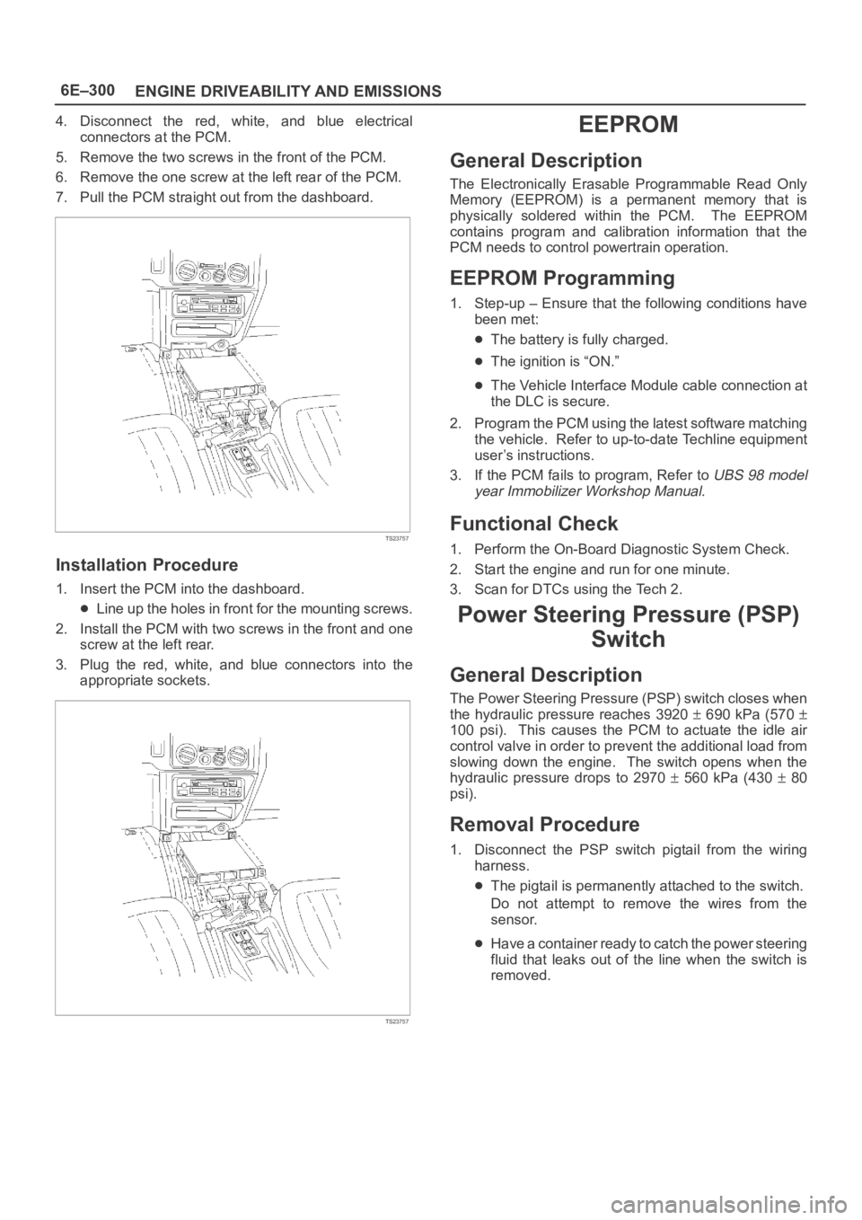
4. Disconnect the red, white, and blue electrical
connectors at the PCM.
5. Remove the two screws in the front of the PCM.
6. Remove the one screw at the left rear of the PCM.
7. Pull the PCM straight out from the dashboard.
TS23757
Installation Procedure
1. Insert the PCM into the dashboard.
Line up the holes in front for the mounting screws.
2. Install the PCM with two screws in the front and one
screw at the left rear.
3. Plug the red, white, and blue connectors into the
appropriate sockets.
TS23757
EEPROM
General Description
The Electronically Erasable Programmable Read Only
Memory (EEPROM) is a permanent memory that is
physically soldered within the PCM. The EEPROM
contains program and calibration information that the
PCM needs to control powertrain operation.
EEPROM Programming
1. Step-up – Ensure that the following conditions have
been met:
The battery is fully charged.
The ignition is “ON.”
The Vehicle Interface Module cable connection at
the DLC is secure.
2. Program the PCM using the latest software matching
the vehicle. Refer to up-to-date Techline equipment
user’s instructions.
3. If the PCM fails to program, Refer to
UBS 98 model
year Immobilizer Workshop Manual.
Functional Check
1. Perform the On-Board Diagnostic System Check.
2. Start the engine and run for one minute.
3. Scan for DTCs using the Tech 2.
Power Steering Pressure (PSP)
Switch
General Description
The Power Steering Pressure (PSP) switch closes when
the hydraulic pressure reaches 3920
690 kPa (570
100 psi). This causes the PCM to actuate the idle air
control valve in order to prevent the additional load from
slowing down the engine. The switch opens when the
hydraulic pressure drops to 2970
560 kPa (430 80
psi).
Removal Procedure
1. Disconnect the PSP switch pigtail from the wiring
harness.
The pigtail is permanently attached to the switch.
Do not attempt to remove the wires from the
sensor.
Have a container ready to catch the power steering
fluid that leaks out of the line when the switch is
removed.
Page 4958 of 6000

6E–301 ENGINE DRIVEABILITY AND EMISSIONS
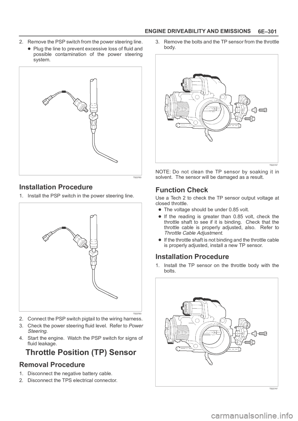
2. Remove the PSP switch from the power steering line.
Plug the line to prevent excessive loss of fluid and
possible contamination of the power steering
system.
TS23760
Installation Procedure
1. Install the PSP switch in the power steering line.
TS23760
2. Connect the PSP switch pigtail to the wiring harness.
3. Check the power steering fluid level. Refer to
Power
Steering
.
4. Start the engine. Watch the PSP switch for signs of
fluid leakage.
Throttle Position (TP) Sensor
Removal Procedure
1. Disconnect the negative battery cable.
2. Disconnect the TPS electrical connector.3. Remove the bolts and the TP sensor from the throttle
body.
TS23747
NOTE: Do not clean the TP sensor by soaking it in
solvent. The sensor will be damaged as a result.
Function Check
Use a Tech 2 to check the TP sensor output voltage at
closed throttle.
The voltage should be under 0.85 volt.
If the reading is greater than 0.85 volt, check the
throttle shaft to see if it is binding. Check that the
throttle cable is properly adjusted, also. Refer to
Throttle Cable Adjustment.
If the throttle shaft is not binding and the throttle cable
is properly adjusted, install a new TP sensor.
Installation Procedure
1. Install the TP sensor on the throttle body with the
bolts.
TS23747
Page 4996 of 6000

6E–339 ENGINE DRIVEABILITY AND EMISSIONS
0005
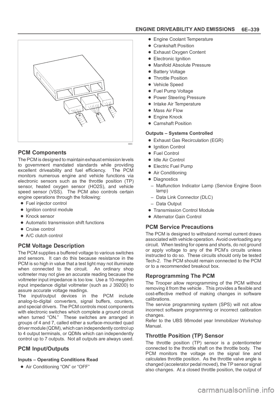
PCM Components
The PCM is designed to maintain exhaust emission levels
to government mandated standards while providing
excellent driveability and fuel efficiency. The PCM
monitors numerous engine and vehicle functions via
electronic sensors such as the throttle position (TP)
sensor, heated oxygen sensor (HO2S), and vehicle
speed sensor (VSS). The PCM also controls certain
engine operations through the following:
Fuel injector control
Ignition control module
Knock sensor
Automatic transmission shift functions
Cruise control
A/C clutch control
PCM Voltage Description
The PCM supplies a buffered voltage to various switches
and sensors. It can do this because resistance in the
PCM is so high in value that a test light may not illuminate
when connected to the circuit. An ordinary shop
voltmeter may not give an accurate reading because the
voltmeter input impedance is too low. Use a 10-megohm
input impedance digital voltmeter (such as J 39200) to
assure accurate voltage readings.
The input/output devices in the PCM include
analog-to-digital converters, signal buffers, counters,
and special drivers. The PCM controls most components
with electronic switches which complete a ground circuit
when turned “ON.” These switches are arranged in
groups of 4 and 7, called either a surface-mounted quad
driver module (QDM), which can independently control up
to 4 output terminals, or QDMs which can independently
control up to 7 outputs. Not all outputs are always used.
PCM Input/Outputs
Inputs – Operating Conditions Read
Air Conditioning “ON” or “OFF”
Engine Coolant Temperature
Crankshaft Position
Exhaust Oxygen Content
Electronic Ignition
Manifold Absolute Pressure
Battery Voltage
Throttle Position
Vehicle Speed
Fuel Pump Voltage
Power Steering Pressure
Intake Air Temperature
Mass Air Flow
Engine Knock
Camshaft Position
Outputs – Systems Controlled
Exhaust Gas Recirculation (EGR)
Ignition Control
Fuel Control
Idle Air Control
Electric Fuel Pump
Air Conditioning
Diagnostics
– Malfunction Indicator Lamp (Service Engine Soon
lamp)
– Data Link Connector (DLC)
– Data Output
Transmission Control Module
Alternator Gain Control
PCM Service Precautions
The PCM is designed to withstand normal current draws
associated with vehicle operation. Avoid overloading any
circuit. When testing for opens and shorts, do not ground
or apply voltage to any of the PCM’s circuits unless
instructed to do so. These circuits should only be tested
Tech-2. The PCM should remain connected to the PCM
or to a recommended breakout box.
Reprogramming The PCM
The Trooper allow reprogramming of the PCM without
removing it from the vehicle . This provides a flexible and
cost-effective method of making changes in software
calibrations.
The service programming system (SPS) will not allow
incorrect software programming or incorrect calibration
changes.
Refer to the UBS 98model year Immobilizer Workshop
Manual.
Throttle Position (TP) Sensor
The throttle position (TP) sensor is a potentiometer
connected to the throttle shaft on the throttle body. The
PCM monitors the voltage on the signal line and
calculates throttle position. As the throttle valve angle is
changed (accelerator pedal moved), the TP sensor signal
also changes. At a closed throttle position, the output of
Page 5321 of 6000

6A – 48 ENGINE MECHANICAL
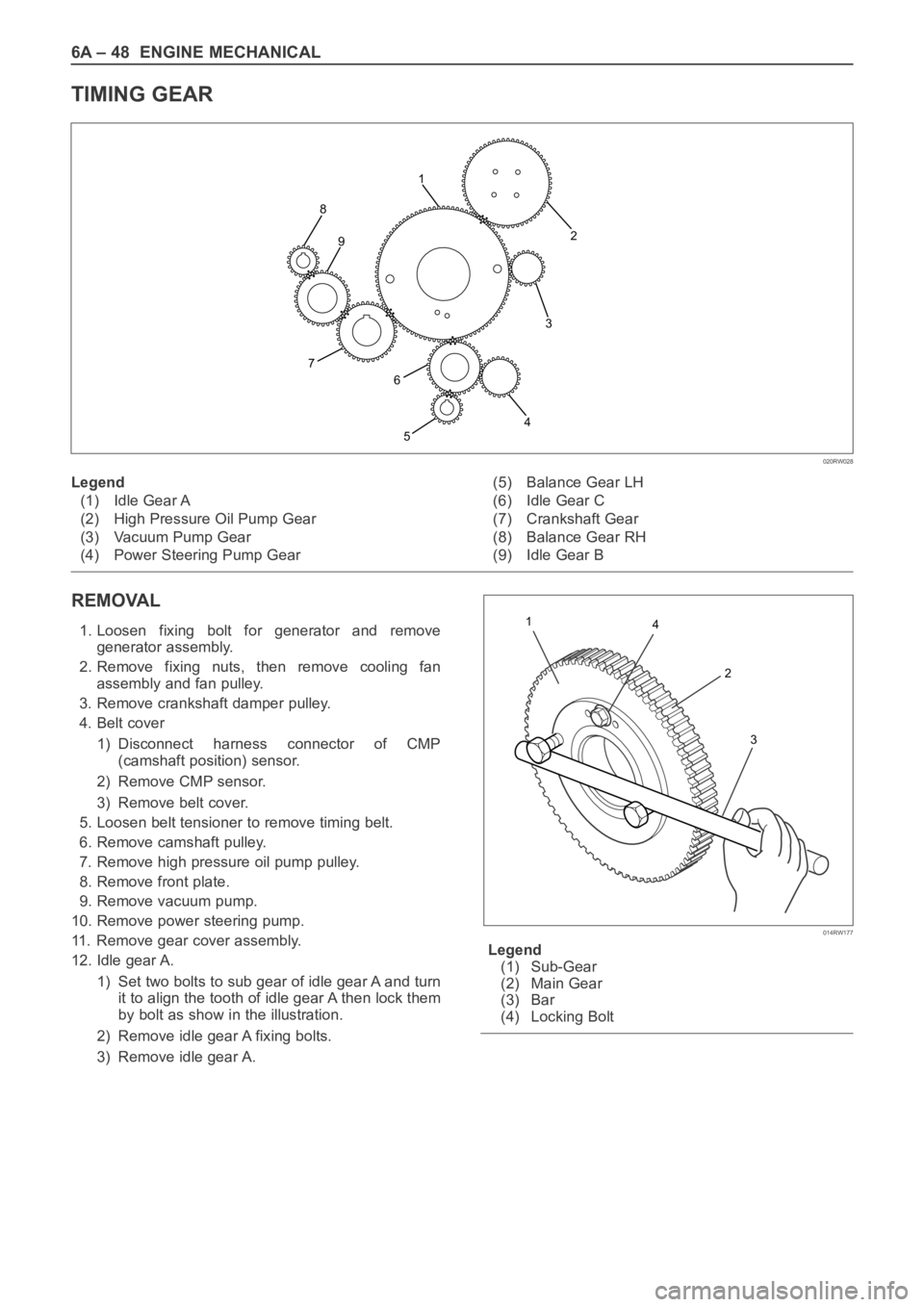
TIMING GEAR
REMOVAL
1. Loosen fixing bolt for generator and remove
generator assembly.
2. Remove fixing nuts, then remove cooling fan
assembly and fan pulley.
3. Remove crankshaft damper pulley.
4. Belt cover
1) Disconnect harness connector of CMP
(camshaft position) sensor.
2) Remove CMP sensor.
3) Remove belt cover.
5. Loosen belt tensioner to remove timing belt.
6. Remove camshaft pulley.
7. Remove high pressure oil pump pulley.
8. Remove front plate.
9. Remove vacuum pump.
10. Remove power steering pump.
11. Remove gear cover assembly.
12. Idle gear A.
1) Set two bolts to sub gear of idle gear A and turn
it to align the tooth of idle gear A then lock them
by bolt as show in the illustration.
2) Remove idle gear A fixing bolts.
3) Remove idle gear A.Legend
(1) Sub-Gear
(2) Main Gear
(3) Bar
(4) Locking Bolt
2
3
4
5 8
7
6 91
020RW028
Legend
(1) Idle Gear A
(2) High Pressure Oil Pump Gear
(3) Vacuum Pump Gear
(4) Power Steering Pump Gear(5) Balance Gear LH
(6) Idle Gear C
(7) Crankshaft Gear
(8) Balance Gear RH
(9) Idle Gear B
4 1
2
3
014RW177
Page 5326 of 6000
ENGINE MECHANICAL 6A – 53
10. Vacuum pump
1) Install vacuum pump and tighten bolts to
specified torque.
Torque: 25 Nꞏm (2.5 kgꞏm / 18 lb ft)
2) Install noise insulator cover.
11. Power steering pump (P/S)
1) Install P/S pump.
Torque: 25 Nꞏm (2.5 kgꞏm / 18 lb ft)12. Install front plate.
Torque: 20 Nꞏm (2.0 kgꞏm / 14.5 lb ft)
13. High pressure oil pump pulley.
1) Install oil pump pulley and tighten to specified
torque.
Torque:10 Nꞏm (1.0 kgꞏm / 7.2 lb ft)
2
2~2.5mm
2~2.5mm
Apply liquid gasket around inside
of the bolt hole
Bolt hole
Inside
Outside
F06HX00001
052RW001
430RW017
012RW035