1998 OPEL FRONTERA fuse
[x] Cancel search: fusePage 5602 of 6000
6E–173 4JX1–TC ENGINE DRIVEABILITY AND EMISSIONS
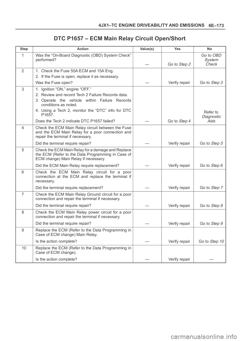
DTC P1657 – ECM Main Relay Circuit Open/Short
StepActionVa l u e ( s )Ye sNo
1Was the “On-Board Diagnostic (OBD) System Check”
performed?
—Go to Step 2
Go to OBD
System
Check
21. Check the Fuse 50AꞏECM and 15AꞏEng.
2. If the Fuse is open, replace it as necessary.
Was the Fuse open?
—Verify repairGo to Step 3
31. Ignition “ON,” engine “OFF.”
2. Review and record Tech 2 Failure Records data.
3. Operate the vehicle within Failure Records
conditions as noted.
4. Using a Tech 2, monitor the “DTC” info for DTC
P1657.
Does the Tech 2 indicate DTC P1657 failed?
—Go to Step 4
Refer to
Diagnostic
Aids
4Check the ECM Main Relay circuit between the Fuse
and the ECM Main Relay for a poor connection and
repair the terminal if necessary.
Did the terminal require repair?
—Verify repairGo to Step 5
5Check the ECM Main Relay for a damage and Replace
the ECM (Refer to the Data Programming in Case of
ECM change) Main Relay if necessary.
Did the ECM Main Relay require replacement?
—Verify repairGo to Step 6
6Check the ECM Main Relay circuit for a poor
connection at the ECM and replace the terminal if
necessary.
Did the terminal require replacement?
—Verify repairGo to Step 7
7Check the ECM Main Relay Ground circuit for a poor
connection and repair the terminal if necessary.
Did the terminal require repair?
—Verify repairGo to Step 8
8Check the ECM Main Relay power circuit for a poor
connection and repair the terminal if necessary.
Did the terminal require repair?
—Verify repairGo to Step 9
9Replace the ECM (Refer to the Data Programming in
Case of ECM change) Main Relay.
Is the action complete?
—Verify repairGo to Step 10
10Replace the ECM (Refer to the Data Programming in
Case of ECM change).
Is the action complete?
—Verify repair—
Page 5603 of 6000
6E–174
4JX1–TC ENGINE DRIVEABILITY AND EMISSIONS
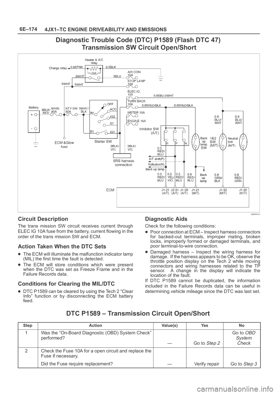
Diagnostic Trouble Code (DTC) P1589 (Flash DTC 47)
Transmission SW Circuit Open/Short
060RW131
Circuit Description
The trans mission SW circuit receives current through
ELEC IG 10A fuse from the battery, current flowing in the
order of the trans mission SW and ECM.
Action Taken When the DTC Sets
The ECM will illuminate the malfunction indicator lamp
(MIL) the first time the fault is detected.
The ECM will store conditions which were present
when the DTC was set as Freeze Frame and in the
Failure Records data.
Conditions for Clearing the MIL/DTC
DTC P1589 can be cleared by using the Tech 2 “Clear
Info” function or by disconnecting the ECM battery
feed.
Diagnostic Aids
Check for the following conditions:
Poor connection at ECM – Inspect harness connectors
for backed-out terminals, improper mating, broken
locks, improperly formed or damaged terminals, and
poor terminal-to-wire connection.
Damaged harness – Inspect the wiring harness for
damage. If the harness appears to be OK, observe the
throttle position display on the Tech 2 while moving
connectors and wiring harnesses related to the TP
sensor. A change in the display will indicate the
location of the fault.
If DTC P1589 cannot be duplicated, the information
included in the Failure Records data can be useful in
determining vehicle mileage since the DTC was last set.
DTC P1589 – Transmission Circuit Open/Short
StepActionVa l u e ( s )Ye sNo
1Was the “On-Board Diagnostic (OBD) System Check”
performed?
—Go to Step 2
Go to OBD
System
Check
2Check the Fuse 10A for a open circuit and replace the
Fuse if necessary.
Did the Fuse require replacement?
—Verify repairGo to Step 3
Page 5620 of 6000
6E–191 4JX1–TC ENGINE DRIVEABILITY AND EMISSIONS
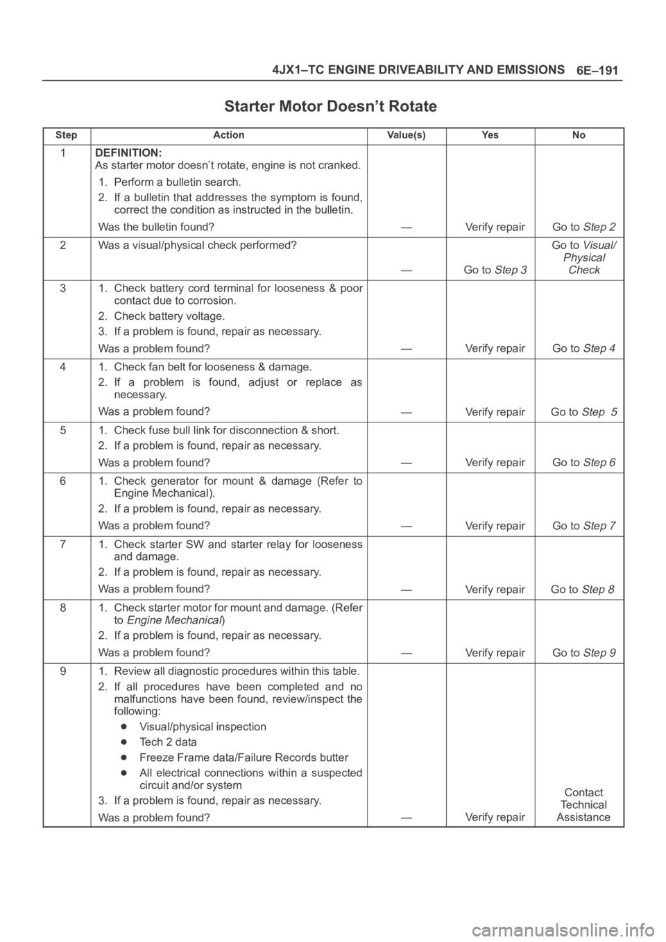
Starter Motor Doesn’t Rotate
StepActionVa l u e ( s )Ye sNo
1DEFINITION:
As starter motor doesn’t rotate, engine is not cranked.
1. Perform a bulletin search.
2. If a bulletin that addresses the symptom is found,
correct the condition as instructed in the bulletin.
Was the bulletin found?
—Verify repairGo to Step 2
2Was a visual/physical check performed?
—Go to Step 3
Go to Visual/
Physical
Check
31. Check battery cord terminal for looseness & poor
contact due to corrosion.
2. Check battery voltage.
3. If a problem is found, repair as necessary.
Was a problem found?
—Verify repairGo to Step 4
41. Check fan belt for looseness & damage.
2. If a problem is found, adjust or replace as
necessary.
Was a problem found?
—Verify repairGo to Step 5
51. Check fuse bull link for disconnection & short.
2. If a problem is found, repair as necessary.
Was a problem found?
—Verify repairGo to Step 6
61. Check generator for mount & damage (Refer to
Engine Mechanical).
2. If a problem is found, repair as necessary.
Was a problem found?
—Verify repairGo to Step 7
71. Check starter SW and starter relay for looseness
and damage.
2. If a problem is found, repair as necessary.
Was a problem found?
—Verify repairGo to Step 8
81. Check starter motor for mount and damage. (Refer
to
Engine Mechanical)
2. If a problem is found, repair as necessary.
Was a problem found?
—Verify repairGo to Step 9
91. Review all diagnostic procedures within this table.
2. If all procedures have been completed and no
malfunctions have been found, review/inspect the
following:
Visual/physical inspection
Te c h 2 d a t a
Freeze Frame data/Failure Records butter
All electrical connections within a suspected
circuit and/or system
3. If a problem is found, repair as necessary.
Was a problem found?
—Verify repair
Contact
Te c h n i c a l
Assistance
Page 5636 of 6000
6E–207 4JX1–TC ENGINE DRIVEABILITY AND EMISSIONS
damage, therefore, it is important to use care when
handling and testing electronic components.
NOTE: To prevent possible Electrostatic Discharge
damage, follow these guidelines:
Do not touch the control module connector pins or
soldered components on the control module circuit
board.
Do not open the replacement part package until the
part is ready to be installed.
Before removing the part from the package, ground
the package to a known good ground on the vehicle.
If the part has been handled while sliding across the
seat, or while sitting down from a standing position, or
while walking a distance, touch a known good ground
before installing the part.
NOTE: To prevent internal ECM damage, the ignition
must be in the “OFF” position in order to disconnect or
reconnect power to the ECM (for example: battery cable,
ECM pigtail, ECM fuse, jumper cables, etc.).
IMPORTANT:When replacing the production ECM
with a service ECM, it is important to transfer the
broadcast code and production ECM number to the
service ECM label. This will allow positive identification of
ECM parts throughout the service life of the vehicle. Do
not record this information on the metal ECM cover.
IMPORTANT:The ignition should always be in the
“OFF” position in order to install or remove the ECM
connectors.
Service of the ECM should normally consist of either re-
placement of the ECM. If the diagnostic procedures call
for the ECM to be replaced, the ECM should be checked
first to ensure it is the correct part. If it is, remove the
faulty ECM and install the new service ECM.
DTC P0601 indicates the check sum error.
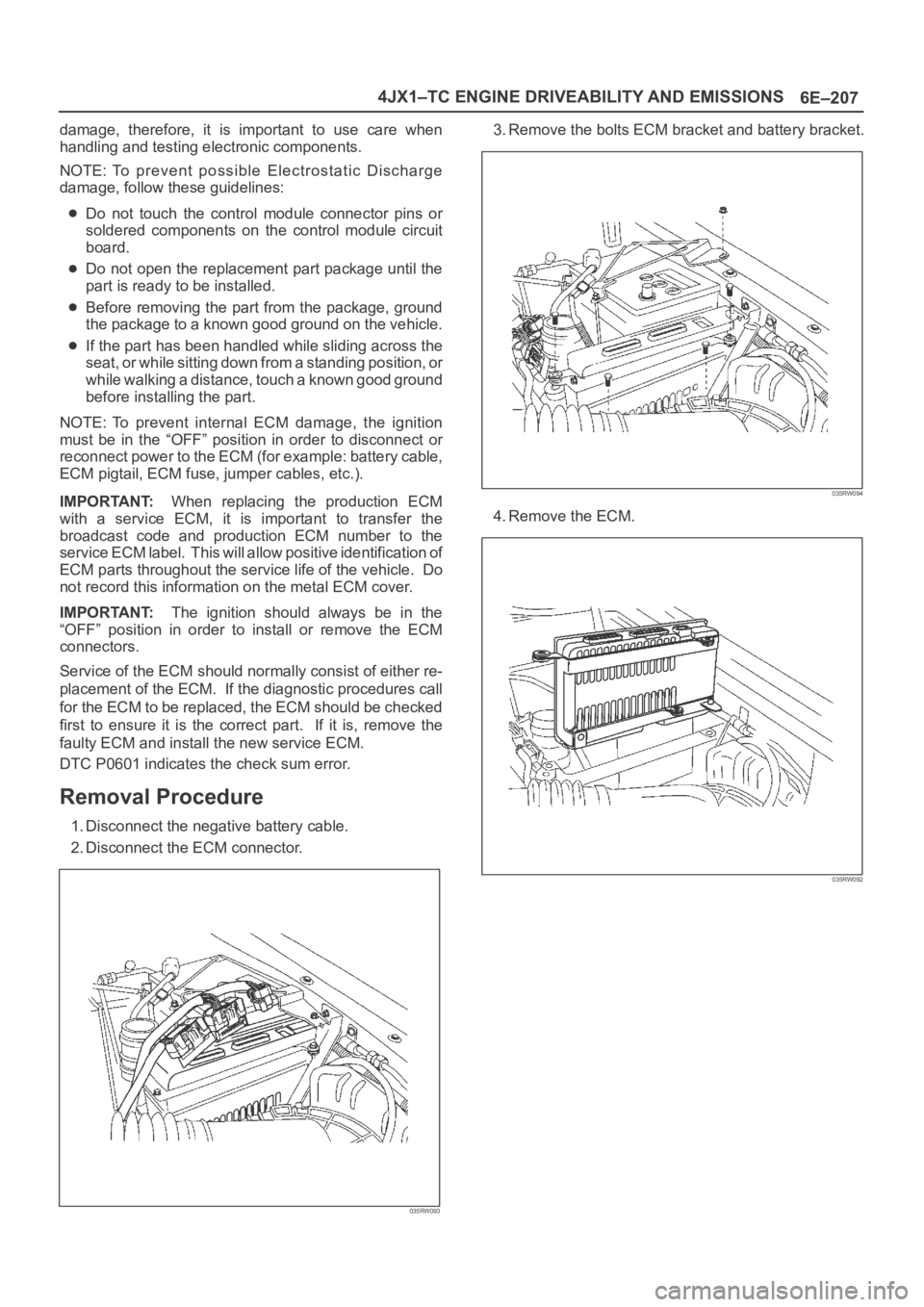
Removal Procedure
1. Disconnect the negative battery cable.
2. Disconnect the ECM connector.
035RW093
3. Remove the bolts ECM bracket and battery bracket.
035RW094
4. Remove the ECM.
035RW092
Page 5646 of 6000
6E–217 4JX1–TC ENGINE DRIVEABILITY AND EMISSIONS
Throttle Body (TB)
Removal Procedure
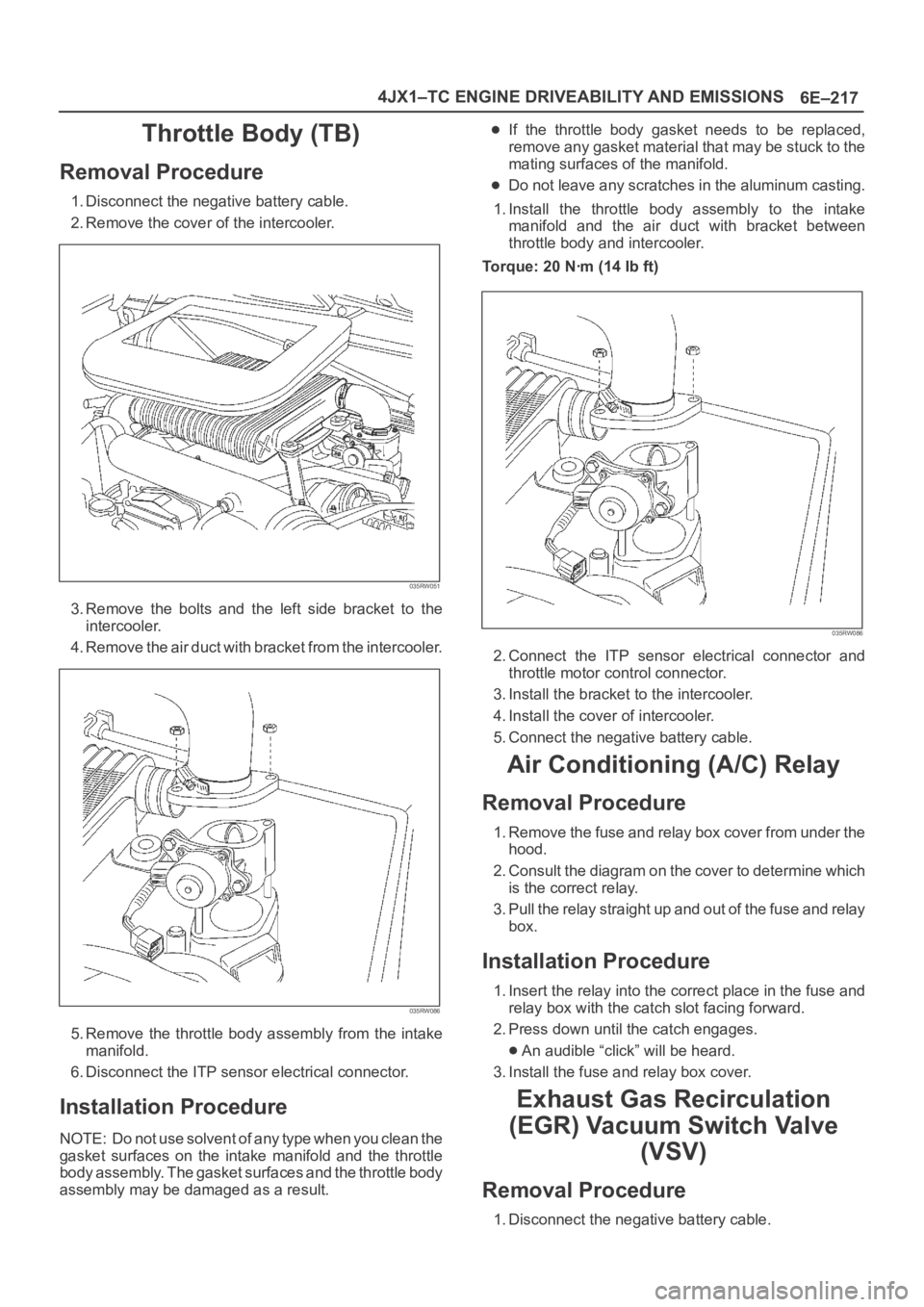
1. Disconnect the negative battery cable.
2. Remove the cover of the intercooler.
035RW051
3. Remove the bolts and the left side bracket to the
intercooler.
4 . R e m o v e t h e a i r d u c t w i t h b r a c k e t f r o m t h e i n t e r c o o l e r.
035RW086
5. Remove the throttle body assembly from the intake
manifold.
6. Disconnect the ITP sensor electrical connector.
Installation Procedure
NOTE: Do not use solvent of any type when you clean the
gasket surfaces on the intake manifold and the throttle
body assembly. The gasket surfaces and the throttle body
assembly may be damaged as a result.
If the throttle body gasket needs to be replaced,
remove any gasket material that may be stuck to the
mating surfaces of the manifold.
Do not leave any scratches in the aluminum casting.
1. Install the throttle body assembly to the intake
manifold and the air duct with bracket between
throttle body and intercooler.
Torque: 20 Nꞏm (14 Ib ft)
035RW086
2. Connect the ITP sensor electrical connector and
throttle motor control connector.
3. Install the bracket to the intercooler.
4. Install the cover of intercooler.
5. Connect the negative battery cable.
Air Conditioning (A/C) Relay
Removal Procedure
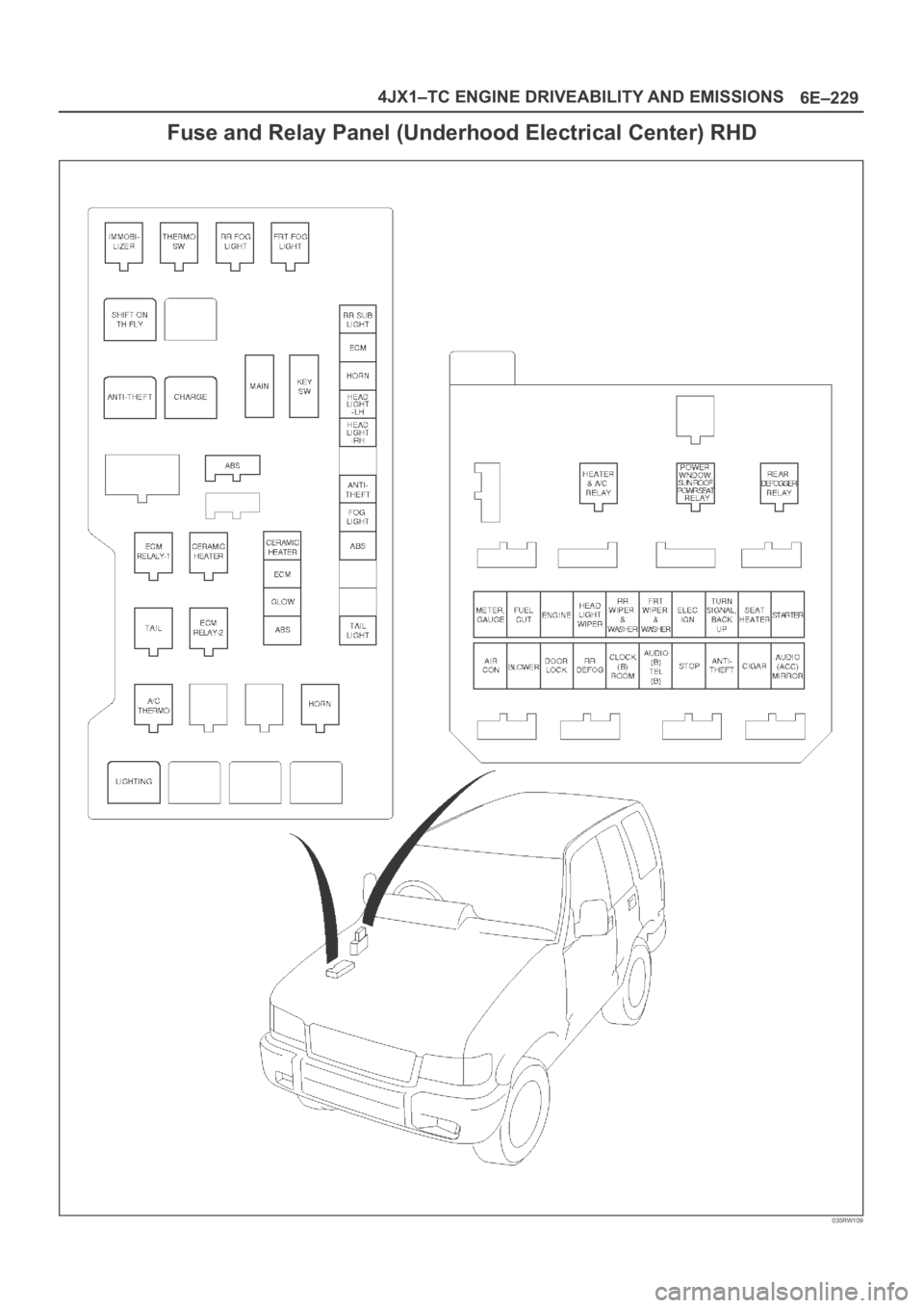
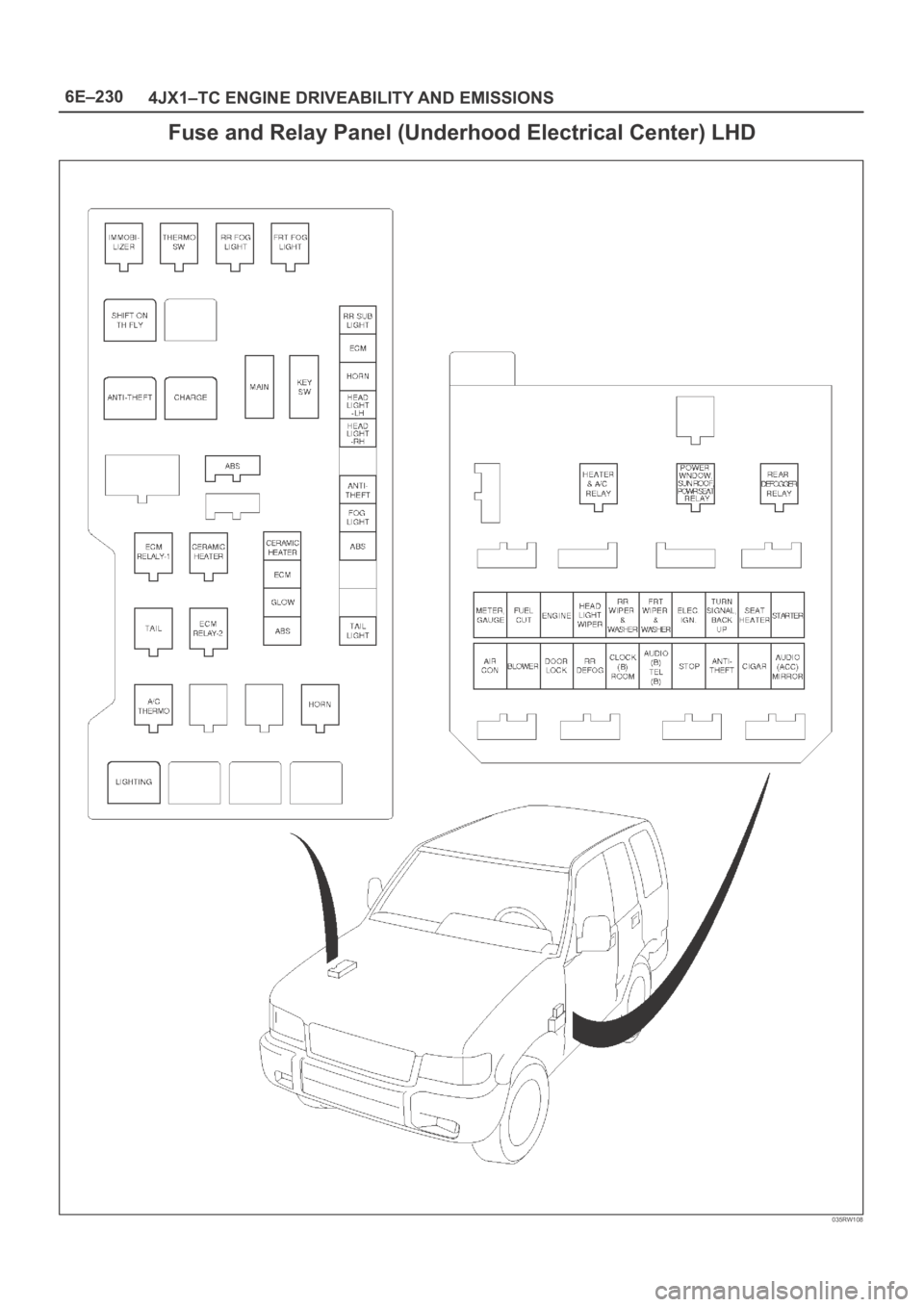
1. Remove the fuse and relay box cover from under the
hood.
2. Consult the diagram on the cover to determine which
is the correct relay.
3. Pull the relay straight up and out of the fuse and relay
box.
Installation Procedure
1. Insert the relay into the correct place in the fuse and
relay box with the catch slot facing forward.
2. Press down until the catch engages.
An audible “click” will be heard.
3. Install the fuse and relay box cover.
Exhaust Gas Recirculation
(EGR) Vacuum Switch Valve
(VSV)
Removal Procedure
1. Disconnect the negative battery cable.
Page 5649 of 6000
6E–220
4JX1–TC ENGINE DRIVEABILITY AND EMISSIONS
Installation Procedure
1. Install the EVRV.
035RW064
2. Connect the EVRV hose and the EVRV connector.
035RW065
3. Connect the negative battery cable.
Wiring and Connectors
Wiring Harness Service
The ECM harness electrically connects the ECM to the
various solenoids, switches and sensors in the vehicle
engine compartment and passenger compartment.
Replace wire harnesses with the proper part number
replacement.
Because of the low amperage and voltage levels utilized
in powertrain control systems, it is essential that all wiring
in environmentally exposed areas be repaired with crimp
and seal splice sleeves.The following wire harness repair information is intended
as a general guideline only. Refer to
Chassis Electrical f o r
all wire harness repair procedures.
Connectors and Terminals
Use care when probing a connector and when replacing
terminals. It is possible to short between opposite
terminals. Damage to components could result. Always
use jumper wires between connectors for circuit
checking. NEVER probe through Weather-Pack seals.
Use an appropriate connector test adapter kit which
contains an assortment of flexible connectors used to
probe terminals during diagnosis. Use an appropriate
fuse remover and test tool for removing a fuse and to
adapt the fuse holder to a meter for diagnosis.
Open circuits are often difficult to locate by sight because
oxidation or terminal misalignment are hidden by the
connectors. Merely wiggling a connector on a sensor, or
in the wiring harness, may temporarily correct the open
circuit. Intermittent problems may also be caused by
oxidized or loose connections.
Be certain of the type of connector/terminal before
making any connector or terminal repair. Weather-Pack
and Com-Pack III terminals look similar, but are serviced
differently.
Wire Harness Repair: Twisted
Shielded Cable
Removal Procedure
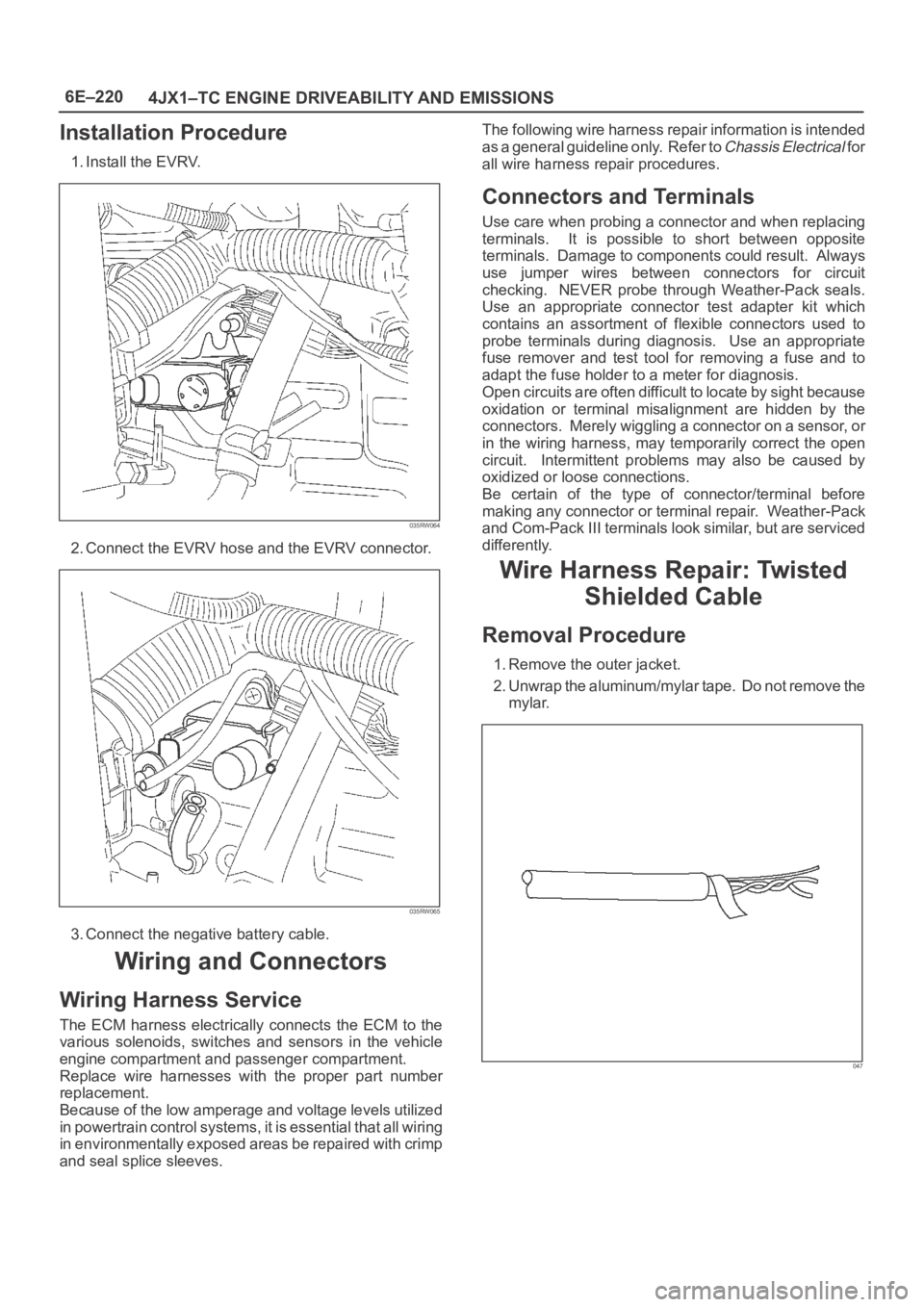
1. Remove the outer jacket.
2. Unwrap the aluminum/mylar tape. Do not remove the
mylar.
047
Page 5658 of 6000
6E–229 4JX1–TC ENGINE DRIVEABILITY AND EMISSIONS
Fuse and Relay Panel (Underhood Electrical Center) RHD
035RW109
Page 5659 of 6000
6E–230
4JX1–TC ENGINE DRIVEABILITY AND EMISSIONS
Fuse and Relay Panel (Underhood Electrical Center) LHD
035RW108