1998 OPEL FRONTERA motor
[x] Cancel search: motorPage 4070 of 6000
4B1–25 DRIVE LINE CONTROL SYSTEM (SHIFT ON THE FLY)
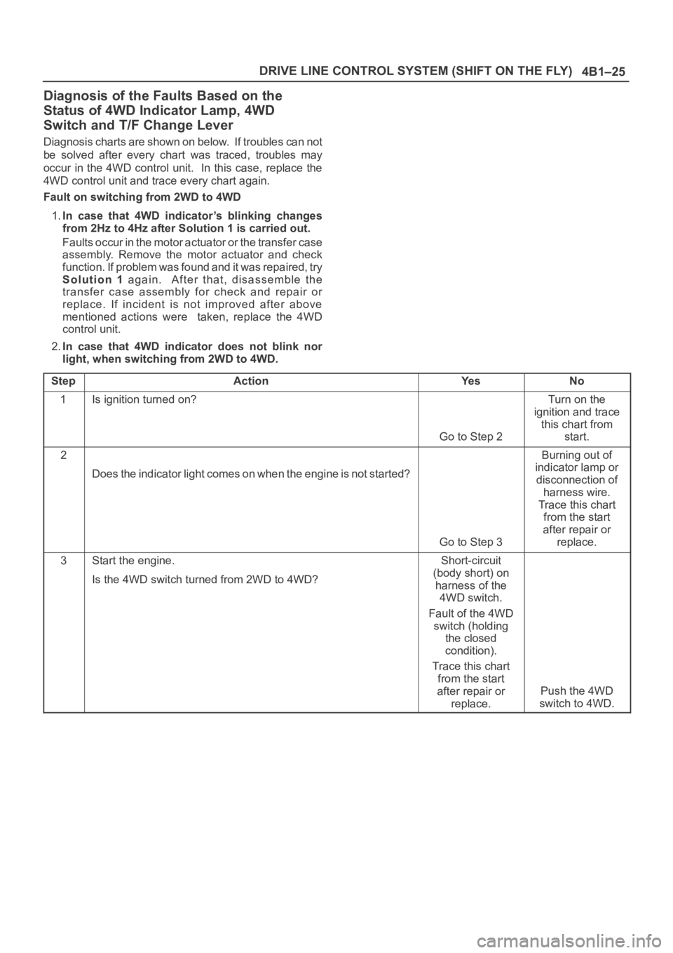
Diagnosis of the Faults Based on the
Status of 4WD Indicator Lamp, 4WD
Switch and T/F Change Lever
Diagnosis charts are shown on below. If troubles can not
be solved after every chart was traced, troubles may
occur in the 4WD control unit. In this case, replace the
4WD control unit and trace every chart again.
Fault on switching from 2WD to 4WD
1.In case that 4WD indicator’s blinking changes
from 2Hz to 4Hz after Solution 1 is carried out.
Faults occur in the motor actuator or the transfer case
assembly. Remove the motor actuator and check
function. If problem was found and it was repaired, try
Solution 1 again. After that, disassemble the
transfer case assembly for check and repair or
replace. If incident is not improved after above
mentioned actions were taken, replace the 4WD
control unit.
2.In case that 4WD indicator does not blink nor
light, when switching from 2WD to 4WD.
Step
ActionYe sNo
1Is ignition turned on?
Go to Step 2
Turn on the
ignition and trace
this chart from
start.
2
Does the indicator light comes on when the engine is not started?
Go to Step 3
Burning out of
indicator lamp or
disconnection of
harness wire.
Trace this chart
from the start
after repair or
replace.
3Start the engine.
Is the 4WD switch turned from 2WD to 4WD?Short-circuit
(body short) on
harness of the
4WD switch.
Fault of the 4WD
switch (holding
the closed
condition).
Trace this chart
from the start
after repair or
replace.
Push the 4WD
switch to 4WD.
Page 4071 of 6000
4B1–26
DRIVE LINE CONTROL SYSTEM (SHIFT ON THE FLY)
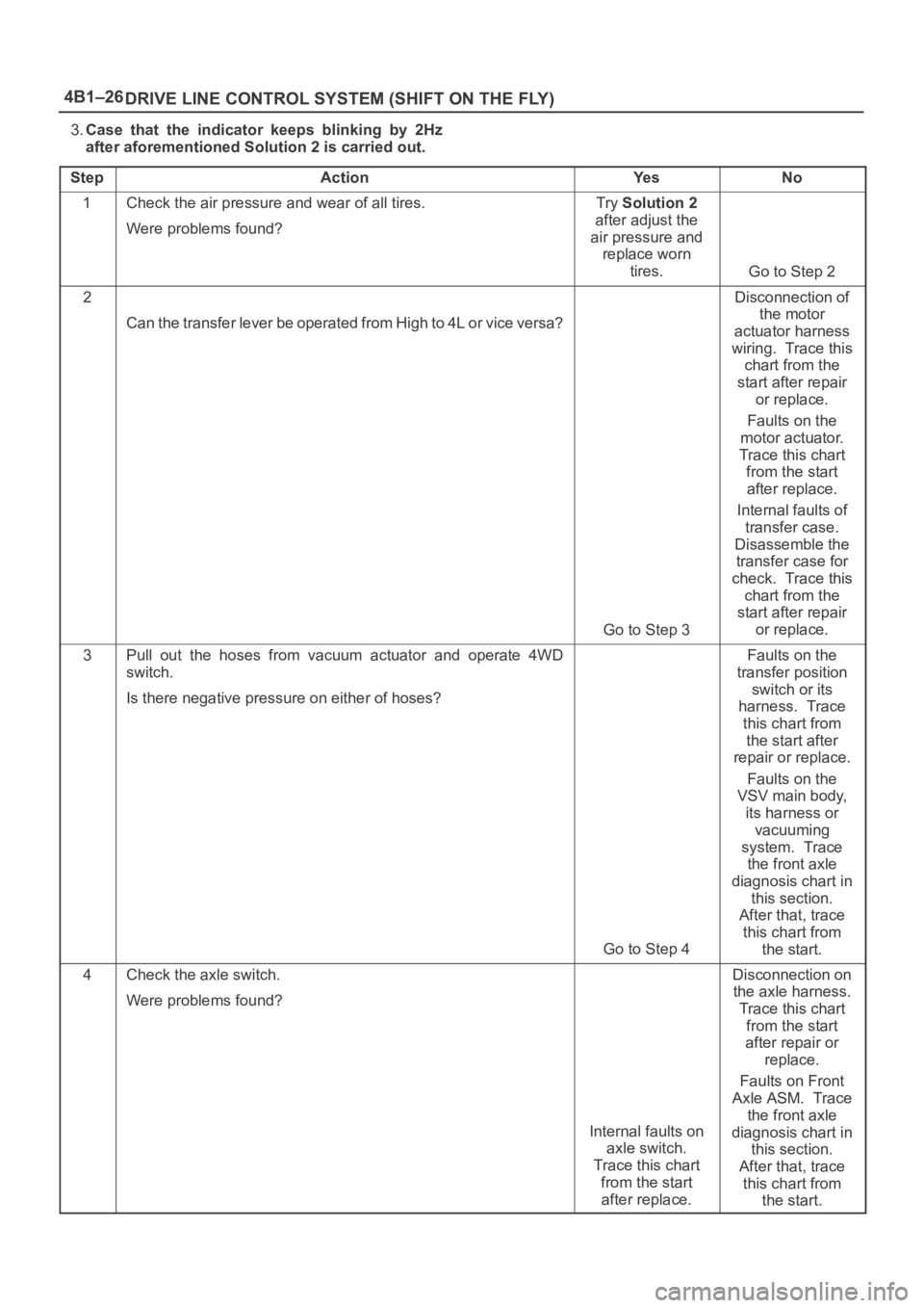
3.Case that the indicator keeps blinking by 2Hz
after aforementioned Solution 2 is carried out.
Step
ActionYe sNo
1Check the air pressure and wear of all tires.
Were problems found?Try Solution 2
after adjust the
air pressure and
replace worn
tires.
Go to Step 2
2
Can the transfer lever be operated from High to 4L or vice versa?
Go to Step 3
Disconnection of
the motor
actuator harness
wiring. Trace this
chart from the
start after repair
or replace.
Faults on the
motor actuator.
Trace this chart
from the start
after replace.
Internal faults of
transfer case.
Disassemble the
transfer case for
check. Trace this
chart from the
start after repair
or replace.
3Pull out the hoses from vacuum actuator and operate 4WD
switch.
Is there negative pressure on either of hoses?
Go to Step 4
Faults on the
transfer position
switch or its
harness. Trace
this chart from
the start after
repair or replace.
Faults on the
VSV main body,
its harness or
vacuuming
system. Trace
the front axle
diagnosis chart in
this section.
After that, trace
this chart from
the start.
4Check the axle switch.
Were problems found?
Internal faults on
axle switch.
Trace this chart
from the start
after replace.
Disconnection on
the axle harness.
Trace this chart
from the start
after repair or
replace.
Faults on Front
Axle ASM. Trace
the front axle
diagnosis chart in
this section.
After that, trace
this chart from
the start.
Page 4073 of 6000
4B1–28
DRIVE LINE CONTROL SYSTEM (SHIFT ON THE FLY)
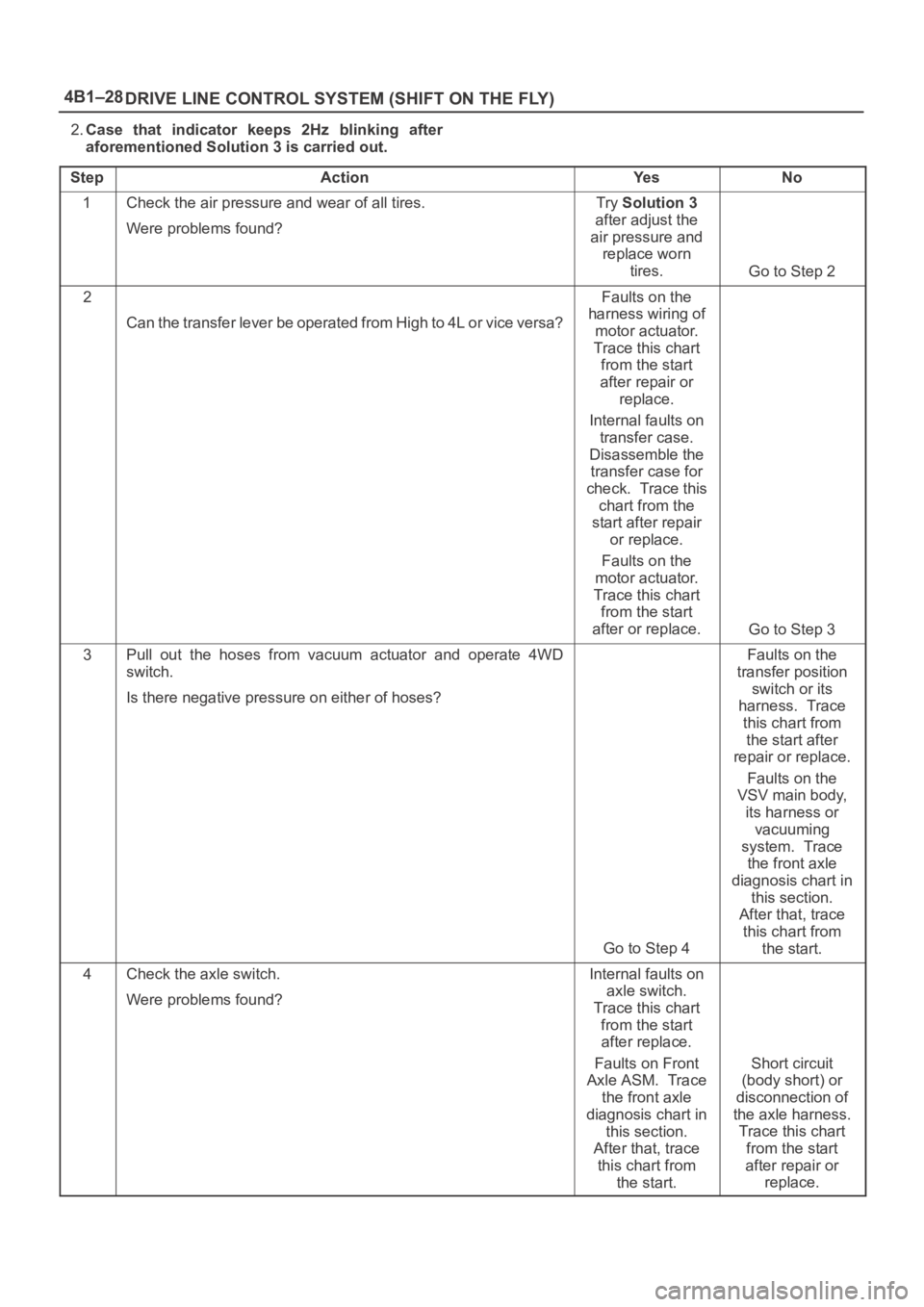
2.Case that indicator keeps 2Hz blinking after
aforementioned Solution 3 is carried out.
Step
ActionYe sNo
1Check the air pressure and wear of all tires.
Were problems found?Try Solution 3
after adjust the
air pressure and
replace worn
tires.
Go to Step 2
2
Can the transfer lever be operated from High to 4L or vice versa?
Faults on the
harness wiring of
motor actuator.
Trace this chart
from the start
after repair or
replace.
Internal faults on
transfer case.
Disassemble the
transfer case for
check. Trace this
chart from the
start after repair
or replace.
Faults on the
motor actuator.
Trace this chart
from the start
after or replace.
Go to Step 3
3Pull out the hoses from vacuum actuator and operate 4WD
switch.
Is there negative pressure on either of hoses?
Go to Step 4
Faults on the
transfer position
switch or its
harness. Trace
this chart from
the start after
repair or replace.
Faults on the
VSV main body,
its harness or
vacuuming
system. Trace
the front axle
diagnosis chart in
this section.
After that, trace
this chart from
the start.
4Check the axle switch.
Were problems found?Internal faults on
axle switch.
Trace this chart
from the start
after replace.
Faults on Front
Axle ASM. Trace
the front axle
diagnosis chart in
this section.
After that, trace
this chart from
the start.
Short circuit
(body short) or
disconnection of
the axle harness.
Trace this chart
from the start
after repair or
replace.
Page 4074 of 6000
4B1–29 DRIVE LINE CONTROL SYSTEM (SHIFT ON THE FLY)
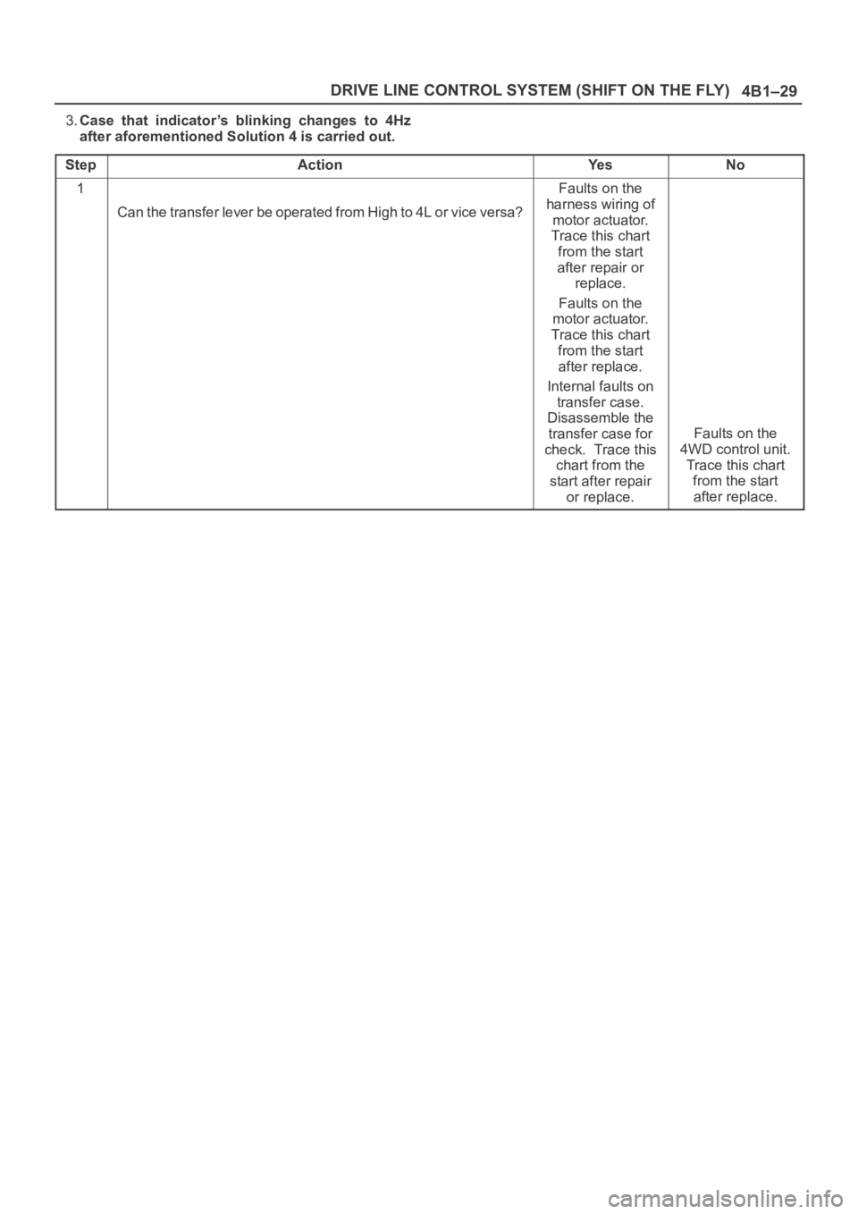
3.Case that indicator’s blinking changes to 4Hz
after aforementioned Solution 4 is carried out.
Step
ActionYe sNo
1
Can the transfer lever be operated from High to 4L or vice versa?
Faults on the
harness wiring of
motor actuator.
Trace this chart
from the start
after repair or
replace.
Faults on the
motor actuator.
Trace this chart
from the start
after replace.
Internal faults on
transfer case.
Disassemble the
transfer case for
check. Trace this
chart from the
start after repair
or replace.
Faults on the
4WD control unit.
Trace this chart
from the start
after replace.
Page 4079 of 6000
4B1–34
DRIVE LINE CONTROL SYSTEM (SHIFT ON THE FLY)
4. If vacuum is not applicable as much as –400mmHg,
and if there is resistance on the intake side, replace
with a new check valve.
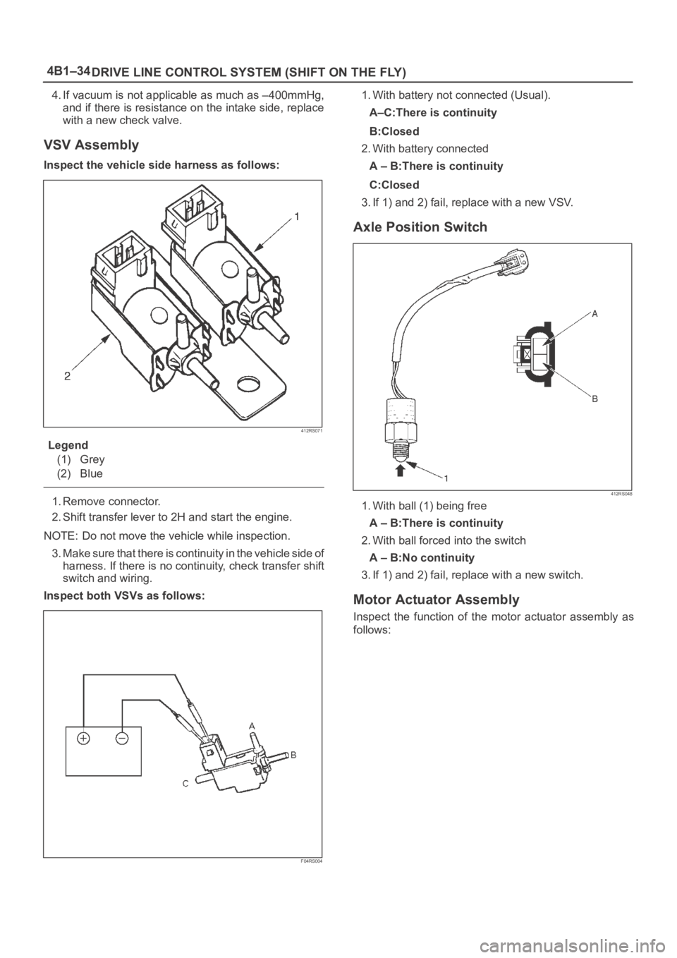
VSV Assembly
Inspect the vehicle side harness as follows:
412RS071
Legend
(1) Grey
(2) Blue
1. Remove connector.
2. Shift transfer lever to 2H and start the engine.
NOTE: Do not move the vehicle while inspection.
3. Make sure that there is continuity in the vehicle side of
harness. If there is no continuity, check transfer shift
switch and wiring.
Inspect both VSVs as follows:
F04RS004
1. With battery not connected (Usual).
A–C:There is continuity
B:Closed
2. With battery connected
A – B:There is continuity
C:Closed
3. If 1) and 2) fail, replace with a new VSV.
Axle Position Switch
412RS048
1. With ball (1) being free
A – B:There is continuity
2. With ball forced into the switch
A – B:No continuity
3. If 1) and 2) fail, replace with a new switch.
Motor Actuator Assembly
Inspect the function of the motor actuator assembly as
follows:
Page 4080 of 6000
4B1–35 DRIVE LINE CONTROL SYSTEM (SHIFT ON THE FLY)
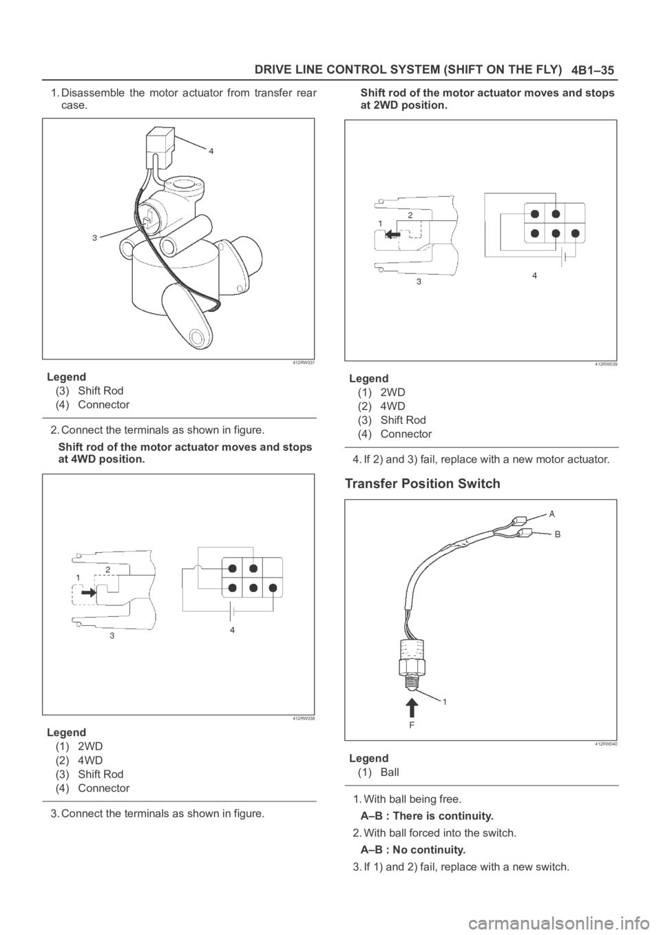
1. Disassemble the motor actuator from transfer rear
case.
412RW037
Legend
(3) Shift Rod
(4) Connector
2. Connect the terminals as shown in figure.
Shift rod of the motor actuator moves and stops
at 4WD position.
412RW038
Legend
(1) 2WD
(2) 4WD
(3) Shift Rod
(4) Connector
3. Connect the terminals as shown in figure.Shift rod of the motor actuator moves and stops
at 2WD position.
412RW039
Legend
(1) 2WD
(2) 4WD
(3) Shift Rod
(4) Connector
4. If 2) and 3) fail, replace with a new motor actuator.
Transfer Position Switch
412RW040
Legend
(1) Ball
1. With ball being free.
A–B : There is continuity.
2. With ball forced into the switch.
A–B : No continuity.
3. If 1) and 2) fail, replace with a new switch.
Page 4351 of 6000
5A–1 BRAKE CONTROL SYSTEM
BRAKES
CONTENTS
Brake Control System 5A. . . . . . . . . . . . . . . . . . . .
Anti–lock Brake System 5B. . . . . . . . . . . . . . . . . . Power–Assisted Brake System 5C. . . . . . . . . . . .
Parking Brakes 5D. . . . . . . . . . . . . . . . . . . . . . . . .
BRAKE CONTROL SYSTEM
CONTENTS
Service Precaution 5A–2. . . . . . . . . . . . . . . . . . . . . .
General Description 5A–3. . . . . . . . . . . . . . . . . . . . .
System Components 5A–3. . . . . . . . . . . . . . . . . . .
Electronic Hydraulic Control Unit (EHCU) 5A–3.
ABS Warning Light 5A–4. . . . . . . . . . . . . . . . . . . .
Wheel Speed Sensor 5A–4. . . . . . . . . . . . . . . . . .
G-Sensor 5A–4. . . . . . . . . . . . . . . . . . . . . . . . . . . . .
Normal and Anti-lock Braking 5A–4. . . . . . . . . . .
Brake Pedal Travel 5A–4. . . . . . . . . . . . . . . . . . . .
Acronyms and Abbreviations 5A–4. . . . . . . . . . . .
General Diagnosis 5A–5. . . . . . . . . . . . . . . . . . . . . . .
General Information 5A–5. . . . . . . . . . . . . . . . . . . .
ABS Service Precautions 5A–5. . . . . . . . . . . . . . .
Computer System Service Precautions 5A–5. . .
General Service Precautions 5A–5. . . . . . . . . . . .
Note on Intermittents 5A–5. . . . . . . . . . . . . . . . . . .
Test Driving ABS Complaint Vehicles 5A–6. . . . .
“ABS” Warning Light 5A–6. . . . . . . . . . . . . . . . . . .
Normal Operation 5A–6. . . . . . . . . . . . . . . . . . . . .
Basic Diagnostic Flow Chart 5A–6. . . . . . . . . . . .
Basic Inspection Procedure 5A–7. . . . . . . . . . . . .
Tech 2 Scan Tool 5A–8. . . . . . . . . . . . . . . . . . . . . .
Getting Started 5A–9. . . . . . . . . . . . . . . . . . . . . . . .
Operating Procedure 5A–10. . . . . . . . . . . . . . . . . . .
Data List 5A–11. . . . . . . . . . . . . . . . . . . . . . . . . . . . .
EHCU Connector Pin-out Checks 5A–12. . . . . . . .
Circuit Diagram (LHD model / 6VD1 and
4JG2) 5A–13. . . . . . . . . . . . . . . . . . . . . . . . . . . . . . .
Circuit Diagram (LHD model / 4JG2) 5A–14. . . . .
Circuit Diagram (LHD model / 4JG2) 5A–15. . . . .
Circuit Diagram (LHD model / 6VD1) 5A–16. . . . .
Circuit Diagram (LHD model / 6VD1) 5A–17. . . . .
Connector List (LHD model) 5A–18. . . . . . . . . . . .
Part Location (LHD model) 5A–20. . . . . . . . . . . . . .
Circuit Diagram (RHD model / 6VD1 and
4JG2) 5A–21. . . . . . . . . . . . . . . . . . . . . . . . . . . . . . .
Circuit Diagram (RHD model / 4JG2) 5A–22. . . . .
Circuit Diagram (RHD model / 4JG2) 5A–23. . . . .
Circuit Diagram (RHD model / 6VD1) 5A–24. . . . .
Circuit Diagram (RHD model / 6VD1) 5A–25. . . . .
Circuit Diagram (RHD model / 6VE1 and
4JX1) 5A–26. . . . . . . . . . . . . . . . . . . . . . . . . . . . . . . . Circuit Diagram (RHD model / 4JX1) 5A–27. . . . .
Circuit Diagram (RHD model / 4JX1) 5A–28. . . . .
Circuit Diagram (RHD model / 6VE1) 5A–29. . . . .
Circuit Diagram (RHD model / 6VE1) 5A–30. . . . .
Connector List (RHD model) 5A–31. . . . . . . . . . . .
Part Location (RHD model) 5A–34. . . . . . . . . . . . .
Symptom Diagnosis 5A–35. . . . . . . . . . . . . . . . . . . . .
Chart A–1 ABS Works Frequently But
Vehicle Does Not Decelerate 5A–35. . . . . . . . . . .
Chart TA-1 ABS Works Frequently But
Vehicle Does Not Decelerate (Use
TECH 2) 5A–36. . . . . . . . . . . . . . . . . . . . . . . . . . . . .
Chart A-2 Uneven Braking Occurs While
ABS Works 5A–36. . . . . . . . . . . . . . . . . . . . . . . . . . .
Chart A-3, TA-3 The Wheels Are Locked 5A–36.
Chart A-4 Brake Pedal Feed Is Abnormal 5A–37.
Chart A-5, TA-5 Braking Sound (From
EHCU) Is Heard While Not Braking 5A–38. . . . . .
Diagnostic Trouble Codes 5A–39. . . . . . . . . . . . . . . .
Diagnosis By “ABS” Warning Light
Illumination Pattern 5A–40. . . . . . . . . . . . . . . . . . . . .
Diagnostic Trouble Codes (DTCs) 5A–40. . . . . . .
Chart B-1 With the key in the ON position
(Before starting the engine). Warning light
(W/L) is not activated. 5A–43. . . . . . . . . . . . . . . . .
Chart B-2 EHCU Abnormality (DTC 14) 5A–43. . .
Chart B-3 Power Voltage Drop (DTC 15) 5A–44. .
Chart B-4 CLASS-2 Communication Line
Abnormality (DTC 16) 5A–44. . . . . . . . . . . . . . . . .
Chart B-5 G-Sensor Circuit (DTC 21) 5A–45. . . . .
Chart B-6 Abnormal Transmission Input
(DTC 23) 5A–46. . . . . . . . . . . . . . . . . . . . . . . . . . . .
Chart B-7 Transfer Monitor (DTC 24) 5A–47. . . . .
Chart B-8 EHCU Pump Motor And Motor
Relay Circuit (DTC 32) 5A–47. . . . . . . . . . . . . . . . .
Chart B-9 EHCU Pump Valve And Valve
Relay Circuit (DTC 35) 5A–47. . . . . . . . . . . . . . . . .
Chart B-10 FL Isolation Solenoid Valve
Abnormality (DTC 41) 5A–48. . . . . . . . . . . . . . . . .
Chart B-11 FL Dump Solenoid Valve
Abnormality (DTC 42) 5A–48. . . . . . . . . . . . . . . . .
Chart B-12 FR Isolation Solenoid Valve
Abnormality (DTC 43) 5A–48. . . . . . . . . . . . . . . . .
Chart B-13 FR Dump Solenoid Valve
Abnormality (DTC 44) 5A–49. . . . . . . . . . . . . . . . .
Chart B-14 Rear Isolation Solenoid Valve
Abnormality (DTC 45) 5A–49. . . . . . . . . . . . . . . . .
Chart B-15 Rear Dump Solenoid Valve
Abnormality (DTC 46) 5A–49. . . . . . . . . . . . . . . . .
Page 4354 of 6000
5A–4
BRAKE CONTROL SYSTEM
normal braking when a malfunction has occurred in the
ABS.
The EHCU has a self-diagnosing function which can
indicate faulty circuits during diagnosis.
The EHCU is mounted on the engine compartment front
right side. It consists of a Motor, Plunger Pump, Solenoid
Valves and Check Valve.
On the outside, the relay box containing a motor relay and
a valve relay is installed.
Solenoid Valves: Reduces or holds the caliper fluid
pressure for each front disc brake or both rear disc brakes
according to the signal sent from the EHCU.
Reservoir: Temporarily holds the brake fluid that returns
from the front and rear disc brake caliper so that pressure
of front disc brake caliper can be reduced smoothly.
Plunger Pump: Feeds the brake fluid held in the reservoir
to the master cylinder.
Motor: Drives the pump according to the signal from
EHCU.
Check Valve: Controls the brake fluid flow.
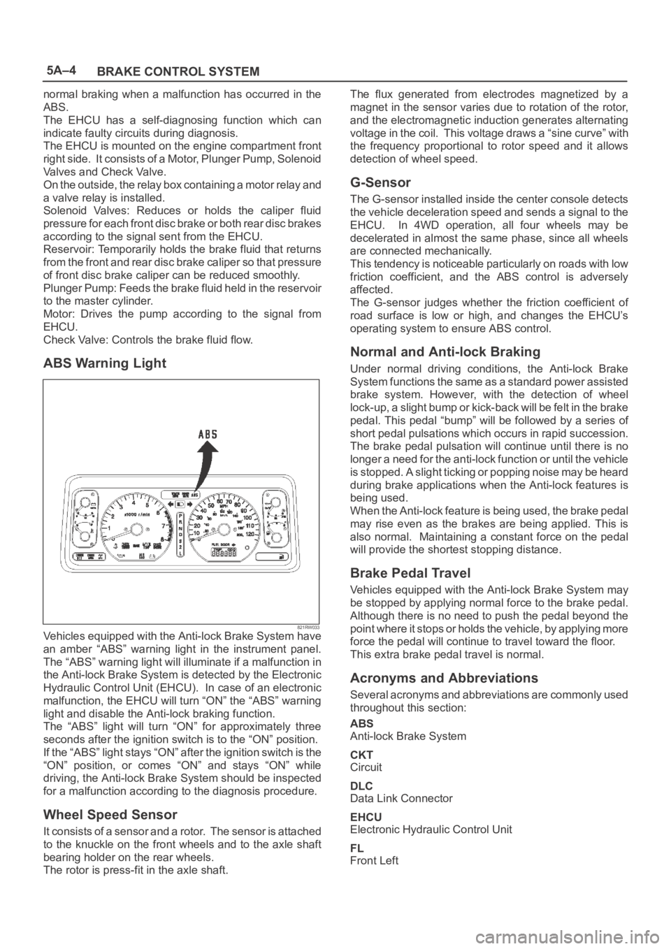
ABS Warning Light
821RW033Vehicles equipped with the Anti-lock Brake System have
an amber “ABS” warning light in the instrument panel.
The “ABS” warning light will illuminate if a malfunction in
the Anti-lock Brake System is detected by the Electronic
Hydraulic Control Unit (EHCU). In case of an electronic
malfunction, the EHCU will turn “ON” the “ABS” warning
light and disable the Anti-lock braking function.
The “ABS” light will turn “ON” for approximately three
seconds after the ignition switch is to the “ON” position.
If the “ABS” light stays “ON” after the ignition switch is the
“ON” position, or comes “ON” and stays “ON” while
driving, the Anti-lock Brake System should be inspected
for a malfunction according to the diagnosis procedure.
Wheel Speed Sensor
It consists of a sensor and a rotor. The sensor is attached
to the knuckle on the front wheels and to the axle shaft
bearing holder on the rear wheels.
The rotor is press-fit in the axle shaft.The flux generated from electrodes magnetized by a
magnet in the sensor varies due to rotation of the rotor,
and the electromagnetic induction generates alternating
voltage in the coil. This voltage draws a “sine curve” with
the frequency proportional to rotor speed and it allows
detection of wheel speed.
G-Sensor
The G-sensor installed inside the center console detects
the vehicle deceleration speed and sends a signal to the
EHCU. In 4WD operation, all four wheels may be
decelerated in almost the same phase, since all wheels
are connected mechanically.
This tendency is noticeable particularly on roads with low
friction coefficient, and the ABS control is adversely
affected.
The G-sensor judges whether the friction coefficient of
road surface is low or high, and changes the EHCU’s
operating system to ensure ABS control.
Normal and Anti-lock Braking
Under normal driving conditions, the Anti-lock Brake
System functions the same as a standard power assisted
brake system. However, with the detection of wheel
lock-up, a slight bump or kick-back will be felt in the brake
pedal. This pedal “bump” will be followed by a series of
short pedal pulsations which occurs in rapid succession.
The brake pedal pulsation will continue until there is no
longer a need for the anti-lock function or until the vehicle
is stopped. A slight ticking or popping noise may be heard
during brake applications when the Anti-lock features is
being used.
When the Anti-lock feature is being used, the brake pedal
may rise even as the brakes are being applied. This is
also normal. Maintaining a constant force on the pedal
will provide the shortest stopping distance.
Brake Pedal Travel
Vehicles equipped with the Anti-lock Brake System may
be stopped by applying normal force to the brake pedal.
Although there is no need to push the pedal beyond the
point where it stops or holds the vehicle, by applying more
force the pedal will continue to travel toward the floor.
This extra brake pedal travel is normal.
Acronyms and Abbreviations
Several acronyms and abbreviations are commonly used
throughout this section:
ABS
Anti-lock Brake System
CKT
Circuit
DLC
Data Link Connector
EHCU
Electronic Hydraulic Control Unit
FL
Front Left