Page 5471 of 6000
6E–42
4JX1–TC ENGINE DRIVEABILITY AND EMISSIONS
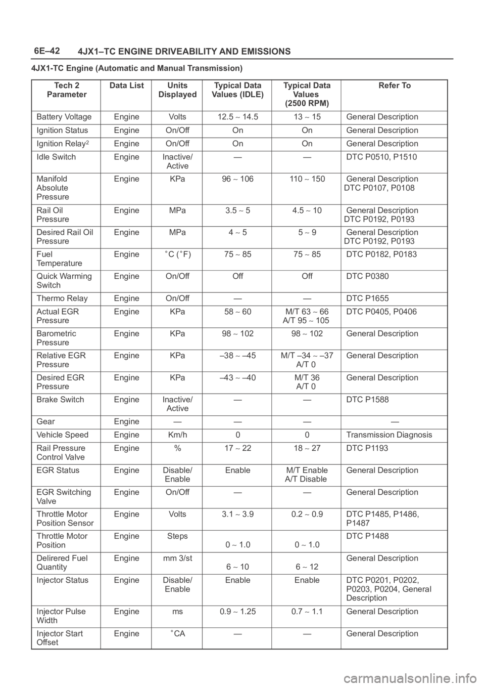
4JX1-TC Engine (Automatic and Manual Transmission)
Te c h 2
Parameter
Data ListUnits
DisplayedTy p i c a l D a t a
Values (IDLE)Typical Data
Va l u e s
(2500 RPM)Refer To
Battery VoltageEngineVo l t s12.5 14.513 15General Description
Ignition StatusEngineOn/OffOnOnGeneral Description
Ignition Relay2EngineOn/OffOnOnGeneral Description
Idle SwitchEngineInactive/
Active——DTC P0510, P1510
Manifold
Absolute
PressureEngineKPa96 106110 150General Description
DTC P0107, P0108
Rail Oil
PressureEngineMPa3.5 54.5 10General Description
DTC P0192, P0193
Desired Rail Oil
PressureEngineMPa4 55 9General Description
DTC P0192, P0193
Fuel
TemperatureEngineC (F)75 8575 85DTC P0182, P0183
Quick Warming
SwitchEngineOn/OffOffOffDTC P0380
Thermo RelayEngineOn/Off——DTC P1655
Actual EGR
PressureEngineKPa58 60M/T 63 66
A/T 95
105
DTC P0405, P0406
Barometric
PressureEngineKPa98 10298 102General Description
Relative EGR
PressureEngineKPa–38 –45M/T –34 –37
A/T 0General Description
Desired EGR
PressureEngineKPa–43 –40M/T 36
A/T 0General Description
Brake SwitchEngineInactive/
Active——DTC P1588
GearEngine————
Vehicle SpeedEngineKm/h00Transmission Diagnosis
Rail Pressure
Control ValveEngine%17 2218 27DTC P1193
EGR StatusEngineDisable/
EnableEnableM/T Enable
A/T DisableGeneral Description
EGR Switching
Va l v eEngineOn/Off——General Description
Throttle Motor
Position SensorEngineVo l t s3.1 3.90.2 0.9DTC P1485, P1486,
P1487
Throttle Motor
PositionEngineSteps
0 1.00 1.0
DTC P1488
Delirered Fuel
QuantityEnginemm 3/st
6 106 12
General Description
Injector StatusEngineDisable/
EnableEnableEnableDTC P0201, P0202,
P0203, P0204, General
Description
Injector Pulse
WidthEnginems0.9 1.250.7 1.1General Description
Injector Start
OffsetEngineCA——General Description
Page 5472 of 6000
6E–43 4JX1–TC ENGINE DRIVEABILITY AND EMISSIONS
Te c h 2
ParameterData ListUnits
DisplayedTy p i c a l D a t a
Values (IDLE)Typical Data
Va l u e s
(2500 RPM)Refer To
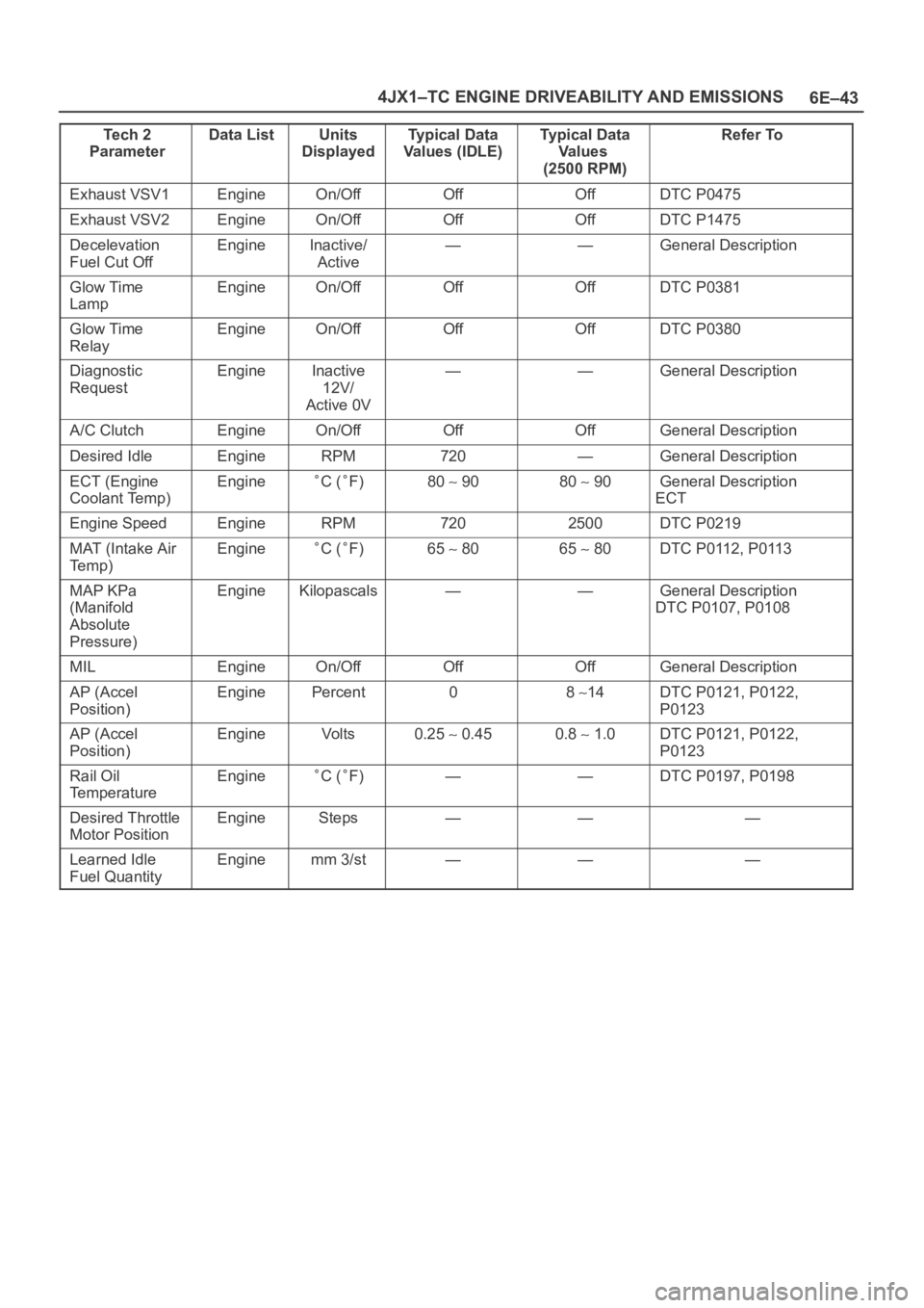
Exhaust VSV1EngineOn/OffOffOffDTC P0475
Exhaust VSV2EngineOn/OffOffOffDTC P1475
Decelevation
Fuel Cut OffEngineInactive/
Active——General Description
Glow Time
LampEngineOn/OffOffOffDTC P0381
Glow Time
RelayEngineOn/OffOffOffDTC P0380
Diagnostic
RequestEngineInactive
12V/
Active 0V——General Description
A/C ClutchEngineOn/OffOffOffGeneral Description
Desired IdleEngineRPM720—General Description
ECT (Engine
Coolant Temp)EngineC (F)80 9080 90General Description
ECT
Engine SpeedEngineRPM7202500DTC P0219
MAT (Intake Air
Te m p )EngineC (F)65 8065 80DTC P0112, P0113
MAP KPa
(Manifold
Absolute
Pressure)EngineKilopascals——General Description
DTC P0107, P0108
MILEngineOn/OffOffOffGeneral Description
AP (Accel
Position)EnginePercent08 14DTC P0121, P0122,
P0123
AP (Accel
Position)EngineVo l t s0.25 0.450.8 1.0DTC P0121, P0122,
P0123
Rail Oil
TemperatureEngineC (F)——DTC P0197, P0198
Desired Throttle
Motor PositionEngineSteps———
Learned Idle
Fuel QuantityEnginemm 3/st———
Page 5484 of 6000
6E–55 4JX1–TC ENGINE DRIVEABILITY AND EMISSIONS
DTC
using a
Te c h 2Flash DTCDescriptionMIL
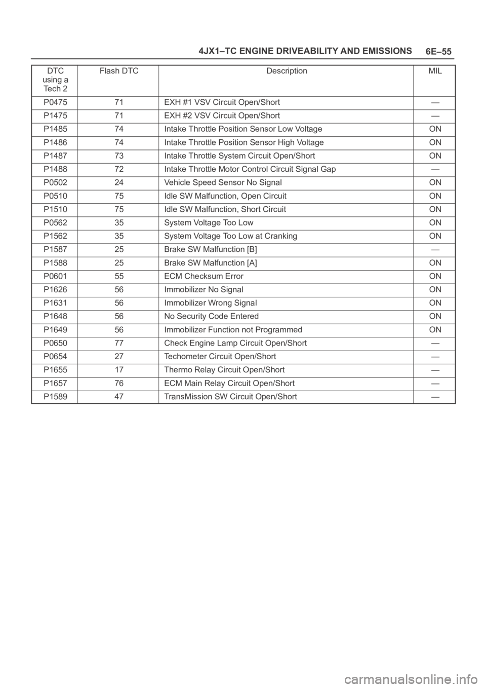
P047571EXH #1 VSV Circuit Open/Short—
P147571EXH #2 VSV Circuit Open/Short—
P148574Intake Throttle Position Sensor Low VoltageON
P148674Intake Throttle Position Sensor High VoltageON
P148773Intake Throttle System Circuit Open/ShortON
P148872Intake Throttle Motor Control Circuit Signal Gap—
P050224Vehicle Speed Sensor No SignalON
P051075Idle SW Malfunction, Open CircuitON
P151075Idle SW Malfunction, Short CircuitON
P056235System Voltage Too LowON
P156235System Voltage Too Low at CrankingON
P158725Brake SW Malfunction [B]—
P158825Brake SW Malfunction [A]ON
P060155ECM Checksum ErrorON
P162656Immobilizer No SignalON
P163156Immobilizer Wrong SignalON
P164856No Security Code EnteredON
P164956Immobilizer Function not ProgrammedON
P065077Check Engine Lamp Circuit Open/Short—
P065427Techometer Circuit Open/Short—
P165517Thermo Relay Circuit Open/Short—
P165776ECM Main Relay Circuit Open/Short—
P158947TransMission SW Circuit Open/Short—
Page 5559 of 6000
6E–130
4JX1–TC ENGINE DRIVEABILITY AND EMISSIONS
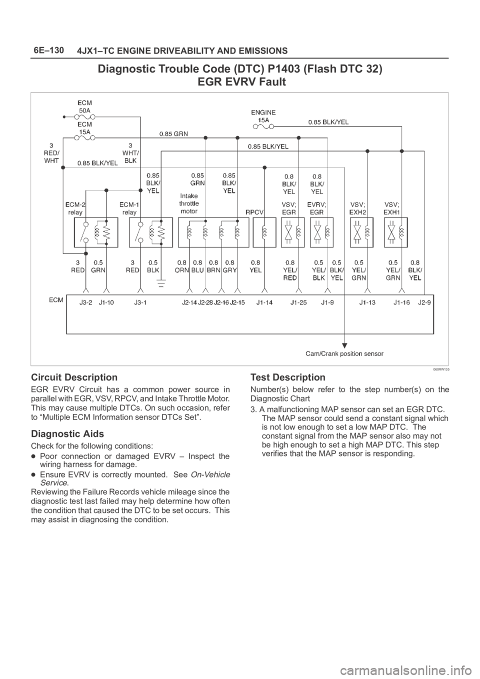
Diagnostic Trouble Code (DTC) P1403 (Flash DTC 32)
EGR EVRV Fault
060RW135
Circuit Description
EGR EVRV Circuit has a common power source in
parallel with EGR, VSV, RPCV, and Intake Throttle Motor.
This may cause multiple DTCs. On such occasion, refer
to “Multiple ECM Information sensor DTCs Set”.
Diagnostic Aids
Check for the following conditions:
Poor connection or damaged EVRV – Inspect the
wiring harness for damage.
Ensure EVRV is correctly mounted. See On-Vehicle
Service.
Reviewing the Failure Records vehicle mileage since the
diagnostic test last failed may help determine how often
the condition that caused the DTC to be set occurs. This
may assist in diagnosing the condition.
Test Description
Number(s) below refer to the step number(s) on the
Diagnostic Chart
3. A malfunctioning MAP sensor can set an EGR DTC.
The MAP sensor could send a constant signal which
is not low enough to set a low MAP DTC. The
constant signal from the MAP sensor also may not
be high enough to set a high MAP DTC. This step
verifies that the MAP sensor is responding.
Page 5565 of 6000
6E–136
4JX1–TC ENGINE DRIVEABILITY AND EMISSIONS
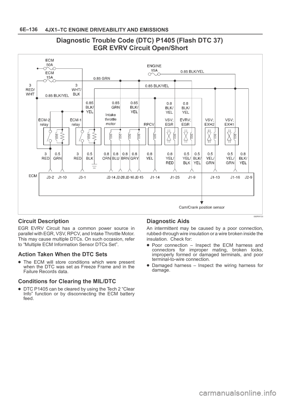
Diagnostic Trouble Code (DTC) P1405 (Flash DTC 37)
EGR EVRV Circuit Open/Short
060RW135
Circuit Description
EGR EVRV Circuit has a common power source in
parallel with EGR, VSV, RPCV, and Intake Throttle Motor.
This may cause multiple DTCs. On such occasion, refer
to “Multiple ECM Information Sensor DTCs Set”.
Action Taken When the DTC Sets
The ECM will store conditions which were present
when the DTC was set as Freeze Frame and in the
Failure Records data.
Conditions for Clearing the MIL/DTC
DTC P1405 can be cleared by using the Tech 2 “Clear
Info” function or by disconnecting the ECM battery
feed.
Diagnostic Aids
An intermittent may be caused by a poor connection,
rubbed-through wire insulation or a wire broken inside the
insulation. Check for:
Poor connection – Inspect the ECM harness and
connectors for improper mating, broken locks,
improperly formed or damaged terminals, and poor
terminal-to-wire connection.
Damaged harness – Inspect the wiring harness for
damage.
Page 5579 of 6000
6E–150
4JX1–TC ENGINE DRIVEABILITY AND EMISSIONS
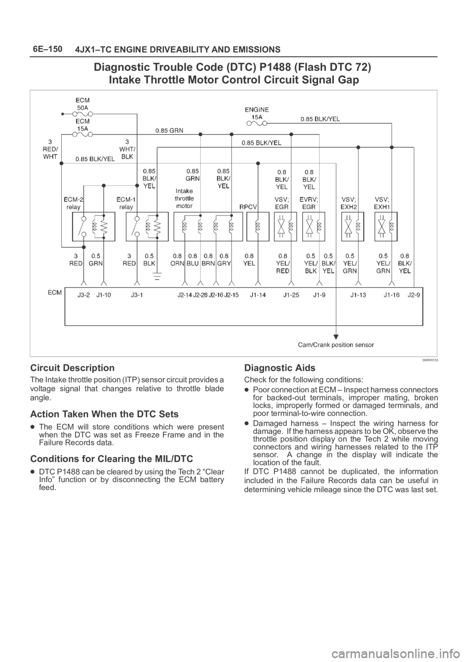
Diagnostic Trouble Code (DTC) P1488 (Flash DTC 72)
Intake Throttle Motor Control Circuit Signal Gap
060RW135
Circuit Description
The Intake throttle position (ITP) sensor circuit provides a
voltage signal that changes relative to throttle blade
angle.
Action Taken When the DTC Sets
The ECM will store conditions which were present
when the DTC was set as Freeze Frame and in the
Failure Records data.
Conditions for Clearing the MIL/DTC
DTC P1488 can be cleared by using the Tech 2 “Clear
Info” function or by disconnecting the ECM battery
feed.
Diagnostic Aids
Check for the following conditions:
Poor connection at ECM – Inspect harness connectors
for backed-out terminals, improper mating, broken
locks, improperly formed or damaged terminals, and
poor terminal-to-wire connection.
Damaged harness – Inspect the wiring harness for
damage. If the harness appears to be OK, observe the
throttle position display on the Tech 2 while moving
connectors and wiring harnesses related to the ITP
sensor. A change in the display will indicate the
location of the fault.
If DTC P1488 cannot be duplicated, the information
included in the Failure Records data can be useful in
determining vehicle mileage since the DTC was last set.
Page 5580 of 6000
6E–151 4JX1–TC ENGINE DRIVEABILITY AND EMISSIONS
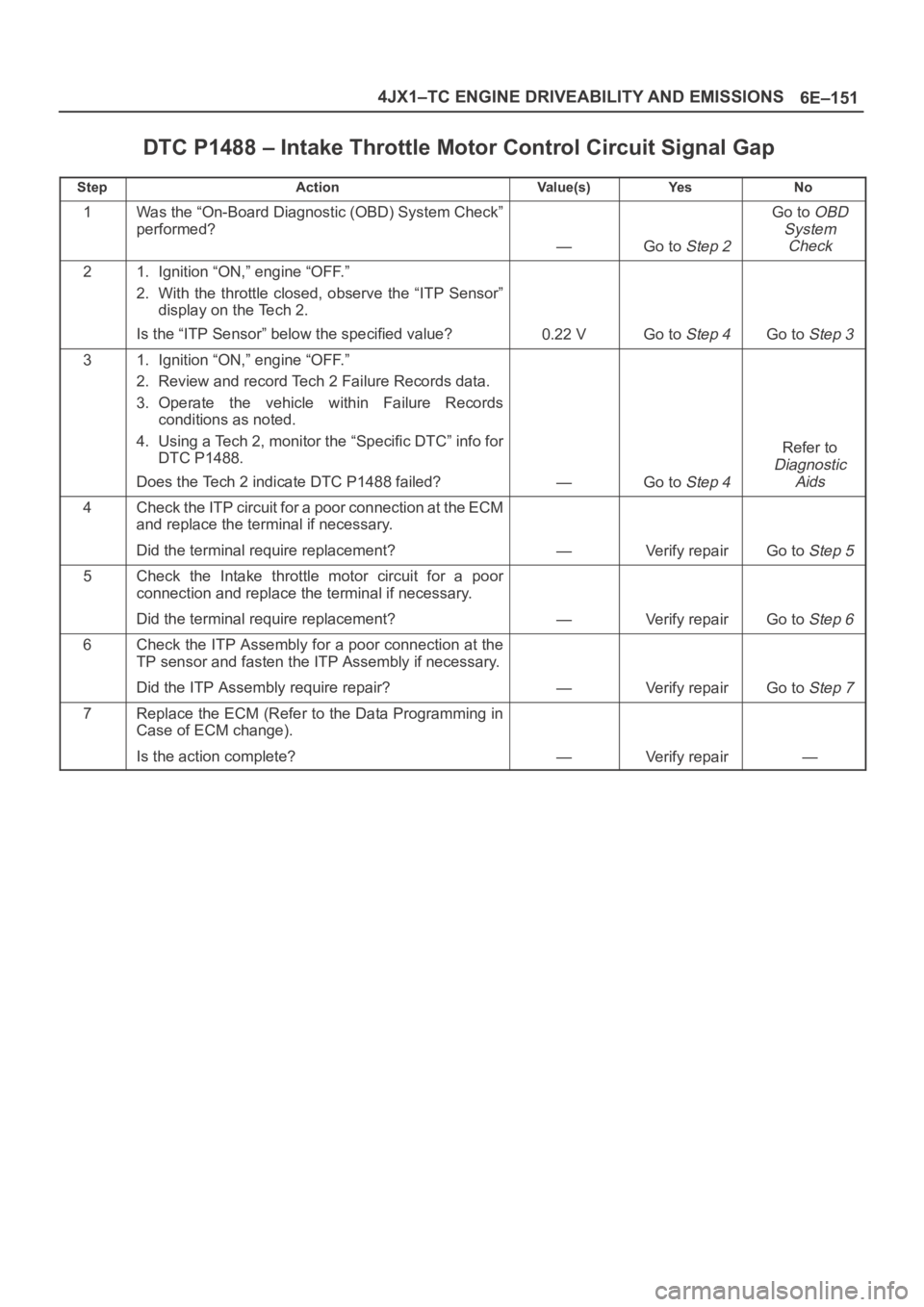
DTC P1488 – Intake Throttle Motor Control Circuit Signal Gap
StepActionVa l u e ( s )Ye sNo
1Was the “On-Board Diagnostic (OBD) System Check”
performed?
—Go to Step 2
Go to OBD
System
Check
21. Ignition “ON,” engine “OFF.”
2. With the throttle closed, observe the “ITP Sensor”
display on the Tech 2.
Is the “ITP Sensor” below the specified value?
0.22 VGo to Step 4Go to Step 3
31. Ignition “ON,” engine “OFF.”
2. Review and record Tech 2 Failure Records data.
3. Operate the vehicle within Failure Records
conditions as noted.
4. Using a Tech 2, monitor the “Specific DTC” info for
DTC P1488.
Does the Tech 2 indicate DTC P1488 failed?
—Go to Step 4
Refer to
Diagnostic
Aids
4Check the ITP circuit for a poor connection at the ECM
and replace the terminal if necessary.
Did the terminal require replacement?
—Verify repairGo to Step 5
5Check the Intake throttle motor circuit for a poor
connection and replace the terminal if necessary.
Did the terminal require replacement?
—Verify repairGo to Step 6
6Check the ITP Assembly for a poor connection at the
TP sensor and fasten the ITP Assembly if necessary.
Did the ITP Assembly require repair?
—Verify repairGo to Step 7
7Replace the ECM (Refer to the Data Programming in
Case of ECM change).
Is the action complete?
—Verify repair—
Page 5619 of 6000
6E–190
4JX1–TC ENGINE DRIVEABILITY AND EMISSIONS
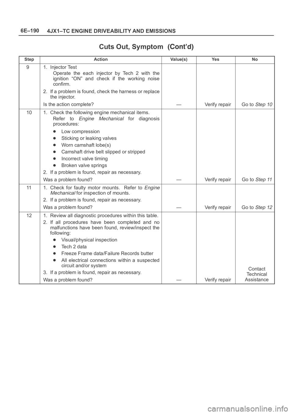
Cuts Out, Symptom
StepNo Ye s Va l u e ( s ) Action
91. Injector Test
Operate the each injector by Tech 2 with the
ignition “ON” and check if the working noise
confirm.
2. If a problem is found, check the harness or replace
the injector.
Is the action complete?
—Verify repairGo to Step 10
101. Check the following engine mechanical items.
Refer to
Engine Mechanical for diagnosis
procedures:
Low compression
Sticking or leaking valves
Worn camshaft lobe(s)
Camshaft drive belt slipped or stripped
Incorrect valve timing
Broken valve springs
2. If a problem is found, repair as necessary.
Was a problem found?
—Verify repairGo to Step 11
111. Check for faulty motor mounts. Refer to Engine
Mechanical
for inspection of mounts.
2. If a problem is found, repair as necessary.
Was a problem found?
—Verify repairGo to Step 12
121. Review all diagnostic procedures within this table.
2. If all procedures have been completed and no
malfunctions have been found, review/inspect the
following:
Visual/physical inspection
Te c h 2 d a t a
Freeze Frame data/Failure Records butter
All electrical connections within a suspected
circuit and/or system
3. If a problem is found, repair as necessary.
Was a problem found?
—Verify repair
Contact
Te c h n i c a l
Assistance