1998 OPEL FRONTERA maintenance
[x] Cancel search: maintenancePage 1462 of 6000
6E–345 ENGINE DRIVEABILITY AND EMISSIONS
0014
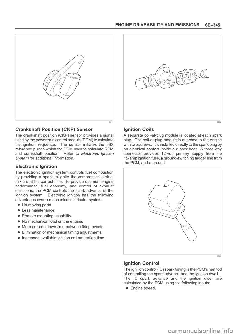
Crankshaft Position (CKP) Sensor
The crankshaft position (CKP) sensor provides a signal
used by the powertrain control module (PCM) to calculate
the ignition sequence. The sensor initiates the 58X
reference pulses which the PCM uses to calculate RPM
and crankshaft position. Refer to
Electronic Ignition
System
for additional information.
Electronic Ignition
The electronic ignition system controls fuel combustion
by providing a spark to ignite the compressed air/fuel
mixture at the correct time. To provide optimum engine
performance, fuel economy, and control of exhaust
emissions, the PCM controls the spark advance of the
ignition system. Electronic ignition has the following
advantages over a mechanical distributor system:
No moving parts.
Less maintenance.
Remote mounting capability.
No mechanical load on the engine.
More coil cooldown time between firing events.
Elimination of mechanical timing adjustments.
Increased available ignition coil saturation time.
0013
Ignition Coils
A separate coil-at-plug module is located at each spark
plug. The coil-at-plug module is attached to the engine
with two screws. It is installed directly to the spark plug by
an electrical contact inside a rubber boot. A three-way
connector provides 12-volt primary supply from the
15-amp ignition fuse, a ground-switching trigger line from
the PCM, and a ground.
0001
Ignition Control
The ignition control (IC) spark timing is the PCM’s method
of controlling the spark advance and the ignition dwell.
The IC spark advance and the ignition dwell are
calculated by the PCM using the following inputs:
Engine speed.
Page 1464 of 6000
6E–347 ENGINE DRIVEABILITY AND EMISSIONS
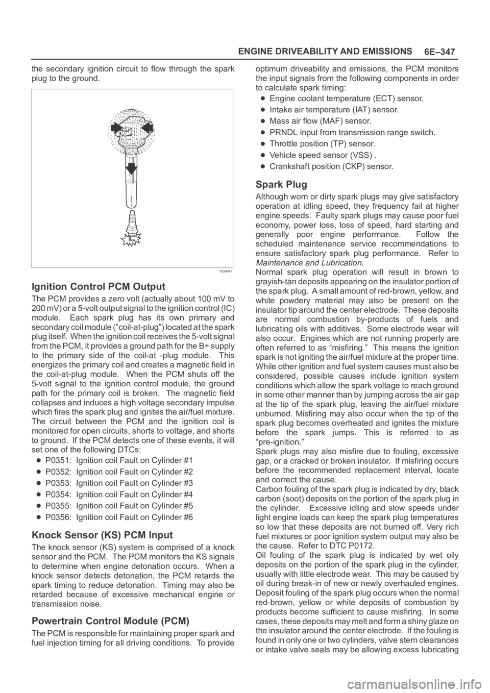
the secondary ignition circuit to flow through the spark
plug to the ground.
TS24047
Ignition Control PCM Output
The PCM provides a zero volt (actually about 100 mV to
200 mV) or a 5-volt output signal to the ignition control (IC)
module. Each spark plug has its own primary and
secondary coil module (”coil-at-plug”) located at the spark
plug itself. When the ignition coil receives the 5-volt signal
from the PCM, it provides a ground path for the B+ supply
to the primary side of the coil-at -plug module. This
energizes the primary coil and creates a magnetic field in
the coil-at-plug module. When the PCM shuts off the
5-volt signal to the ignition control module, the ground
path for the primary coil is broken. The magnetic field
collapses and induces a high voltage secondary impulse
which fires the spark plug and ignites the air/fuel mixture.
The circuit between the PCM and the ignition coil is
monitored for open circuits, shorts to voltage, and shorts
to ground. If the PCM detects one of these events, it will
set one of the following DTCs:
P0351: Ignition coil Fault on Cylinder #1
P0352: Ignition coil Fault on Cylinder #2
P0353: Ignition coil Fault on Cylinder #3
P0354: Ignition coil Fault on Cylinder #4
P0355: Ignition coil Fault on Cylinder #5
P0356: Ignition coil Fault on Cylinder #6
Knock Sensor (KS) PCM Input
The knock sensor (KS) system is comprised of a knock
sensor and the PCM. The PCM monitors the KS signals
to determine when engine detonation occurs. When a
knock sensor detects detonation, the PCM retards the
spark timing to reduce detonation. Timing may also be
retarded because of excessive mechanical engine or
transmission noise.
Powertrain Control Module (PCM)
The PCM is responsible for maintaining proper spark and
fuel injection timing for all driving conditions. To provideoptimum driveability and emissions, the PCM monitors
the input signals from the following components in order
to calculate spark timing:
Engine coolant temperature (ECT) sensor.
Intake air temperature (IAT) sensor.
Mass air flow (MAF) sensor.
PRNDL input from transmission range switch.
Throttle position (TP) sensor.
Vehicle speed sensor (VSS) .
Crankshaft position (CKP) sensor.
Spark Plug
Although worn or dirty spark plugs may give satisfactory
operation at idling speed, they frequency fail at higher
engine speeds. Faulty spark plugs may cause poor fuel
economy, power loss, loss of speed, hard starting and
generally poor engine performance. Follow the
scheduled maintenance service recommendations to
ensure satisfactory spark plug performance. Refer to
Maintenance and Lubrication.
Normal spark plug operation will result in brown to
grayish-tan deposits appearing on the insulator portion of
the spark plug. A small amount of red-brown, yellow, and
white powdery material may also be present on the
insulator tip around the center electrode. These deposits
are normal combustion by-products of fuels and
lubricating oils with additives. Some electrode wear will
also occur. Engines which are not running properly are
often referred to as “misfiring.” This means the ignition
spark is not igniting the air/fuel mixture at the proper time.
While other ignition and fuel system causes must also be
considered, possible causes include ignition system
conditions which allow the spark voltage to reach ground
in some other manner than by jumping across the air gap
at the tip of the spark plug, leaving the air/fuel mixture
unburned. Misfiring may also occur when the tip of the
spark plug becomes overheated and ignites the mixture
before the spark jumps. This is referred to as
“pre-ignition.”
Spark plugs may also misfire due to fouling, excessive
gap, or a cracked or broken insulator. If misfiring occurs
before the recommended replacement interval, locate
and correct the cause.
Carbon fouling of the spark plug is indicated by dry, black
carbon (soot) deposits on the portion of the spark plug in
the cylinder. Excessive idling and slow speeds under
light engine loads can keep the spark plug temperatures
so low that these deposits are not burned off. Very rich
fuel mixtures or poor ignition system output may also be
the cause. Refer to DTC P0172.
Oil fouling of the spark plug is indicated by wet oily
deposits on the portion of the spark plug in the cylinder,
usually with little electrode wear. This may be caused by
oil during break-in of new or newly overhauled engines.
Deposit fouling of the spark plug occurs when the normal
red-brown, yellow or white deposits of combustion by
products become sufficient to cause misfiring. In some
c a s e s , t h e s e d e p o s i t s m a y m e l t a n d f o r m a s h i n y g l a z e o n
the insulator around the center electrode. If the fouling is
found in only one or two cylinders, valve stem clearances
or intake valve seals may be allowing excess lubricating
Page 1465 of 6000
6E–348
ENGINE DRIVEABILITY AND EMISSIONS
oil to enter the cylinder, particularly if the deposits are
heavier on the side of the spark plug facing the intake
valve.
TS23995
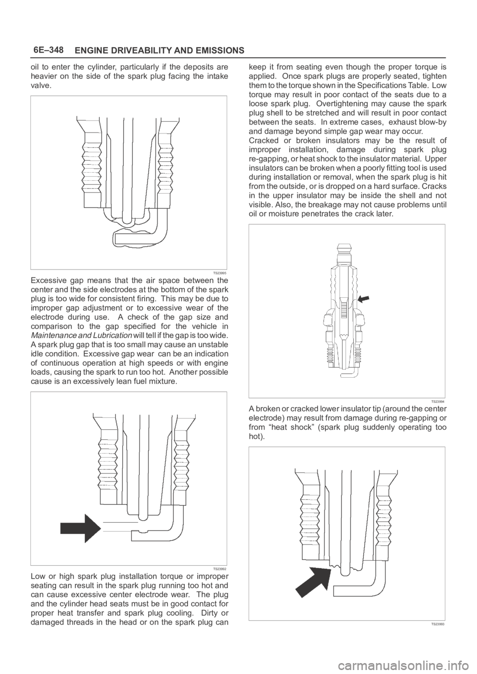
Excessive gap means that the air space between the
center and the side electrodes at the bottom of the spark
plug is too wide for consistent firing. This may be due to
improper gap adjustment or to excessive wear of the
electrode during use. A check of the gap size and
comparison to the gap specified for the vehicle in
Maintenance and Lubrication will tell if the gap is too wide.
A spark plug gap that is too small may cause an unstable
idle condition. Excessive gap wear can be an indication
of continuous operation at high speeds or with engine
loads, causing the spark to run too hot. Another possible
cause is an excessively lean fuel mixture.
TS23992
Low or high spark plug installation torque or improper
seating can result in the spark plug running too hot and
can cause excessive center electrode wear. The plug
and the cylinder head seats must be in good contact for
proper heat transfer and spark plug cooling. Dirty or
damaged threads in the head or on the spark plug cankeep it from seating even though the proper torque is
applied. Once spark plugs are properly seated, tighten
them to the torque shown in the Specifications Table. Low
torque may result in poor contact of the seats due to a
loose spark plug. Overtightening may cause the spark
plug shell to be stretched and will result in poor contact
between the seats. In extreme cases, exhaust blow-by
and damage beyond simple gap wear may occur.
Cracked or broken insulators may be the result of
improper installation, damage during spark plug
re-gapping, or heat shock to the insulator material. Upper
insulators can be broken when a poorly fitting tool is used
during installation or removal, when the spark plug is hit
from the outside, or is dropped on a hard surface. Cracks
in the upper insulator may be inside the shell and not
visible. Also, the breakage may not cause problems until
oil or moisture penetrates the crack later.
TS23994
A broken or cracked lower insulator tip (around the center
electrode) may result from damage during re-gapping or
from “heat shock” (spark plug suddenly operating too
hot).
TS23993
Page 1474 of 6000
6F–3 ENGINE EXHAUST
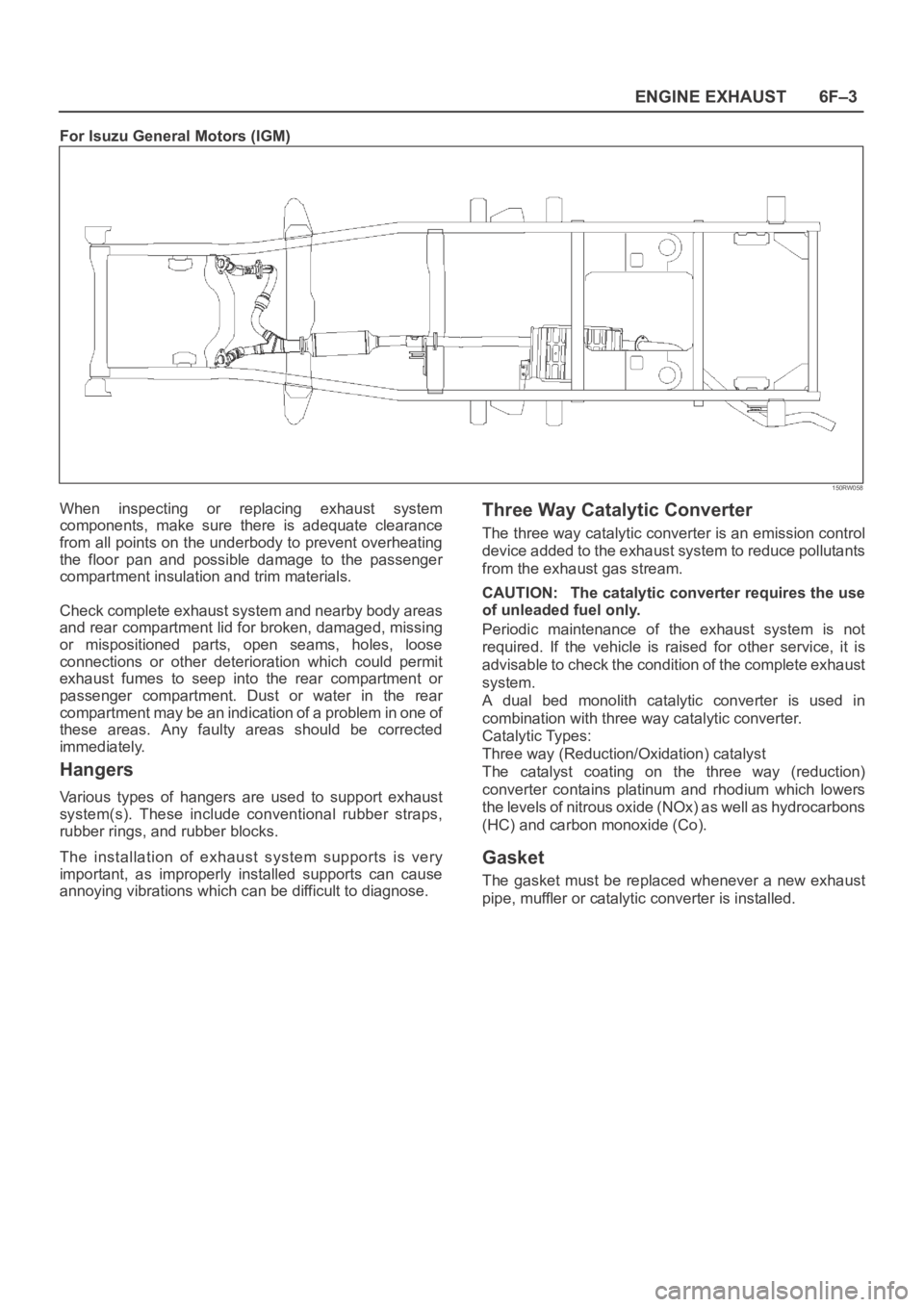
For Isuzu General Motors (IGM)
150RW058
When inspecting or replacing exhaust system
components, make sure there is adequate clearance
from all points on the underbody to prevent overheating
the floor pan and possible damage to the passenger
compartment insulation and trim materials.
Check complete exhaust system and nearby body areas
and rear compartment lid for broken, damaged, missing
or mispositioned parts, open seams, holes, loose
connections or other deterioration which could permit
exhaust fumes to seep into the rear compartment or
passenger compartment. Dust or water in the rear
compartment may be an indication of a problem in one of
these areas. Any faulty areas should be corrected
immediately.
Hangers
Various types of hangers are used to support exhaust
system(s). These include conventional rubber straps,
rubber rings, and rubber blocks.
The installation of exhaust system supports is very
important, as improperly installed supports can cause
annoying vibrations which can be difficult to diagnose.
Three Way Catalytic Converter
The three way catalytic converter is an emission control
device added to the exhaust system to reduce pollutants
from the exhaust gas stream.
CAUTION: The catalytic converter requires the use
of unleaded fuel only.
Periodic maintenance of the exhaust system is not
required. If the vehicle is raised for other service, it is
advisable to check the condition of the complete exhaust
system.
A dual bed monolith catalytic converter is used in
combination with three way catalytic converter.
Catalytic Types:
Three way (Reduction/Oxidation) catalyst
The catalyst coating on the three way (reduction)
converter contains platinum and rhodium which lowers
the levels of nitrous oxide (NOx) as well as hydrocarbons
(HC) and carbon monoxide (Co).
Gasket
The gasket must be replaced whenever a new exhaust
pipe, muffler or catalytic converter is installed.
Page 1742 of 6000
ENGINE MECHANICAL 6A – 9
SERVICING
Servicing refers to general maintenance procedures to
be performed by qualified service personnel.
MODEL IDENTIFICATION
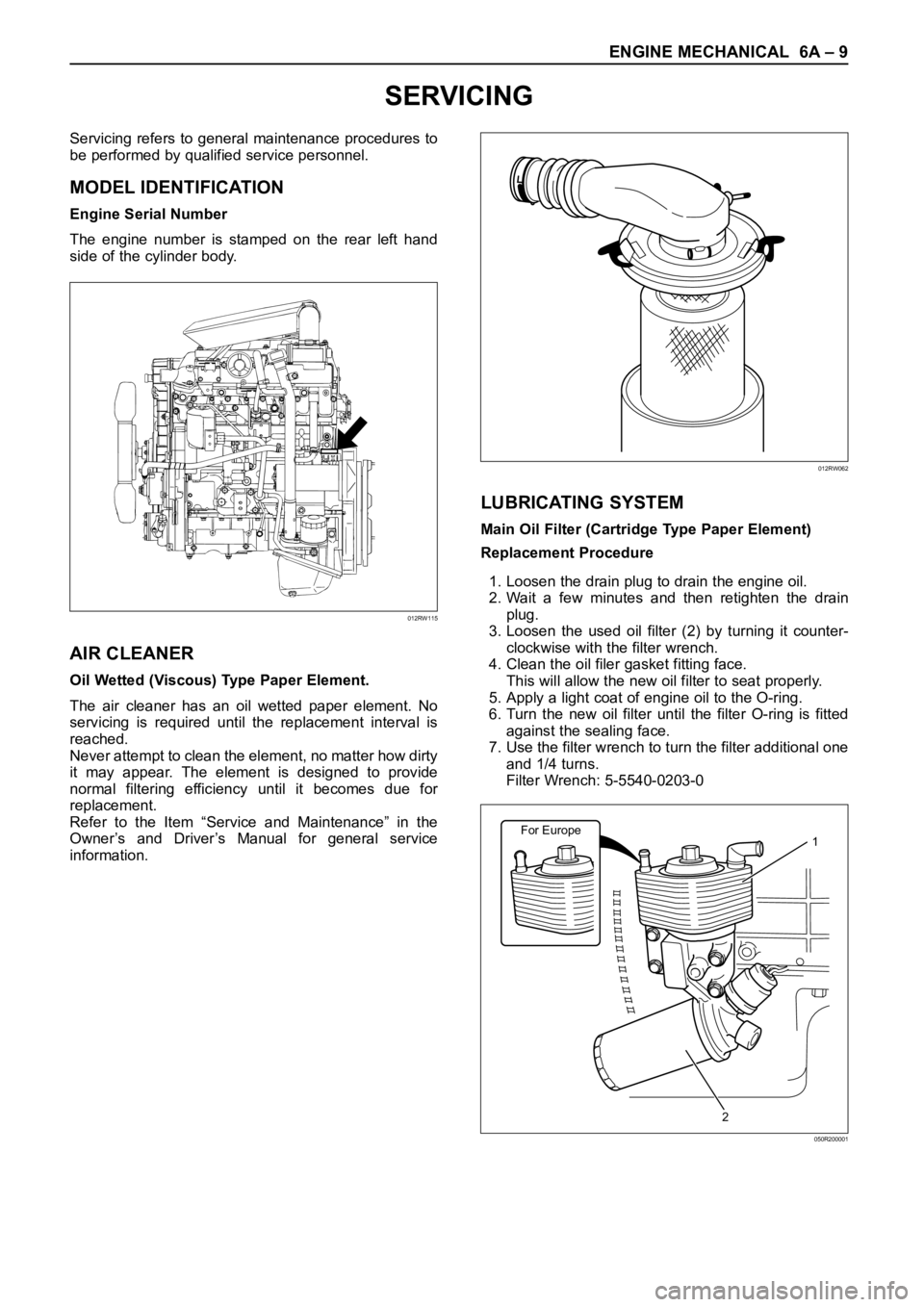
Engine Serial Number
The engine number is stamped on the rear left hand
side of the cylinder body.
AIR CLEANER
Oil Wetted (Viscous) Type Paper Element.
The air cleaner has an oil wetted paper element. No
servicing is required until the replacement interval is
reached.
Never attempt to clean the element, no matter how dirty
it may appear. The element is designed to provide
normal filtering efficiency until it becomes due for
replacement.
Refer to the Item “Service and Maintenance” in the
Owner’s and Driver’s Manual for general service
information.
LUBRICATING SYSTEM
Main Oil Filter (Cartridge Type Paper Element)
Replacement Procedure
1. Loosen the drain plug to drain the engine oil.
2. Wait a few minutes and then retighten the drain
plug.
3. Loosen the used oil filter (2) by turning it counter-
clockwise with the filter wrench.
4. Clean the oil filer gasket fitting face.
This will allow the new oil filter to seat properly.
5. Apply a light coat of engine oil to the O-ring.
6. Turn the new oil filter until the filter O-ring is fitted
against the sealing face.
7. Use the filter wrench to turn the filter additional one
and 1/4 turns.
Filter Wrench: 5-5540-0203-0
012RW115
012RW062
For Europe1
2
050R200001
Page 1846 of 6000

ENGINE FUEL 6C – 1
ENGINE FUEL
CONTENTS
GENERAL DESCRIPTION
General Description . . . . . . . . . . . . . . . . . . 6C–1
On-Vehicle Service . . . . . . . . . . . . . . . . . . 6C–7
Fuel Filter Assembly . . . . . . . . . . . . . . . . 6C–7
Fuel Filter Cartridge . . . . . . . . . . . . . . . . 6C–7
Injector . . . . . . . . . . . . . . . . . . . . . . . . . . 6C–9
Fuel Pump Pipe . . . . . . . . . . . . . . . . . . . 6C–13High Pressure Oil Pump . . . . . . . . . . . . . 6C–15
Fuel Tank . . . . . . . . . . . . . . . . . . . . . . . . 6C–20
Fuel Gauge Unit . . . . . . . . . . . . . . . . . . . 6C–21
Fuel Filler Cap . . . . . . . . . . . . . . . . . . . . 6C–21
To realize the compatibility between low exhaust
emission and high engine output, an HEUI
(Hydraulically actuated Electronically controlled Unit
Injector) system, has been introduced. This system is
comprised of a hydraulic system, fuel system, and
electronic control system, using a high-pressure oil
pump in place of the conventional fuel injection pump.
The oil pressurized by means of this pump and by
signals from the ECM (Electronic Control Module)
actuates the fuel injector provided for each cylinder.
Inside of the fuel injector, fuel pressure is increased due
to the high-pressure oil. The ECM detects the driving
state of the vehicle, forms, signals sent by engine and
other part sensors, which determines the optimum fuel
injection amount and timing, thus controlling the fuel
injectors. Thus high engine output, good fuel economy,
and low exhaust emission are realized.When working on the fuel system, there are several
things to keep in mind:
1) Any time the fuel system is being worked on,
disconnect the negative battery cable except for
those tests where battery voltage is required.
2) Always keep a dry chemical (Class B) fire
extinguisher near the work area.
3) Replace all pipes with the same pipe and fittings
that were removed.
Clean and inspect “O” rings. Replace where
required.
4) Always relieve the line pressure before servicing
any fuel system components.
5) Do not attempt repairs on the fuel system until you
have read the instructions and checked the pictures
relating to that repair.
6) After maintenance work, push priming pump and
send enough fuel to the fuel system before starting
the engine.
NOTE: In comparison with the conventional engine,
the capacity of fuel passage in the 4JX1 engine is
larger. It takes the priming pump more time to fill the
engine with fuel.
Page 1882 of 6000

ENGINE ELECTRICAL 6D – 15
CHARGING SYSTEM
GENERAL DESCRIPTION
GENERATOR
CHARGING CIRCUIT
The charging system is the IC integral regulator
charging system and its main components are
connected as shown in Figure.
The regulator is a solid state type and it is mounted
along with the brush holder assembly inside the
generator installed on the rear end cover.The generator does not require particular maintenance
such as voltage adjustment. The rectifier connected to
the stator coil has nine diodes to transform A.C. voltage
into D.C. voltage. This D.C. voltage is connected to the
output terminal of generator.
A06RW001
Condenser
GeneratorStator Coil
IC RegulatorStarter
SW
Rotor Coil
Battery
P F
EBS LRelay B
S
L
QOS
065R200028
Page 1918 of 6000
6E–25 4JX1–TC ENGINE DRIVEABILITY AND EMISSIONS
General Service Information
Serviceability Issues
Non-OEM Parts
All of the OBD diagnostics have been calibrated to run
with OEM parts. Accordingly, if commercially sold sensor
or switch is installed, it makes a wrong diagnosis and turn
on the MIL (“Check Engine” lamp).
Aftermarket electronics, such as cellular phones,
stereos, and anti-theft devices, may radiate EMI into the
control system if they are improperly installed. This may
cause a false sensor reading and turn on the MIL (“Check
Engine” lamp).
Poor Vehicle Maintenance
The sensitivity of OBD diagnostics will cause the MIL
(“Check Engine” lamp) to turn on if the vehicle is not
maintained properly. Restricted oil filters, fuel filters, and
crankcase deposits due to lack of oil changes or improper
oil viscosity can trigger actual vehicle faults that were not
previously monitored prior to OBD. Poor vehicle
maintenance can not be classified as a “non-vehicle
fault”, but with the sensitivity of OBD diagnostics, vehicle
maintenance schedules must be more closely followed.
Related System Faults
Many of the OBD system diagnostics will not run if the
ECM detects a fault on a related system or component.
Visual/Physical Engine Compartment
Inspection
Perform a careful visual and physical engine
compartment inspection when performing any diagnostic
procedure or diagnosing the cause of an emission test
failure. This can often lead to repairing a problem without
further steps. Use the following guidelines when
performing a visual/physical inspection:
Inspect all vacuum hoses for punches, cuts,
disconnects, and correct routing.
Inspect hoses that are difficult to see behind other
components.
Inspect all wires in the engine compartment for proper
connections, burned or chafed spots, pinched wires,
contact with sharp edges or contact with hot exhaust
manifolds or pipes.
Basic Knowledge of Tools Required
NOTE: Lack of basic knowledge of this powertrain when
performing diagnostic procedures could result in an
incorrect diagnosis or damage to powertrain
components. Do not attempt to diagnose a powertrain
problem without this basic knowledge.
A basic understanding of hand tools is necessary to effec-
tively use this section of the Service Manual.
Serial Data Communications
Class II Serial Data Communications
This vehicle utilizes the “Class II” communication system.
Each bit of information can have one of two lengths: longor short. This allows vehicle wiring to be reduced by
transmitting and receiving multiple signals over a single
wire. The messages carried on Class II data streams are
also prioritized. If two messages attempt to establish
communications on the data line at the same time, only
the message with higher priority will continue. The device
with the lower priority message must wait.
On this vehicle the Tech 2 displays the actual values for
vehicle parameters. It will not be necessary to perform
any conversions from coded values to actual values.
On-Board Diagnostic (OBD)
On-Board Diagnostic Tests
A diagnostic test is a series of steps, the result of which is
a pass or fail reported to the diagnostic executive. When
a diagnostic test reports a pass result, the diagnostic
executive records the following data:
The diagnostic test has been completed since the last
ignition cycle.
The diagnostic test has passed during the current
ignition cycle.
The fault identified by the diagnostic test is not
currently active.
When a diagnostic test reports a fail result, the diagnostic
executive records the following data:
The diagnostic test has been completed since the last
ignition cycle.
The fault identified by the diagnostic test is currently
active.
The fault has been active during this ignition cycle.
The operating conditions at the time of the failure.
Comprehensive Component Monitor
Diagnostic Operation
Comprehensive component monitoring diagnostics are
required to operate engine properly.
Input Components:
Input components are monitored for circuit continuity and
out-of-range values. This includes rationality checking.
Rationality checking refers to indicating a fault when the
signal from a sensor does not seem reasonable. Accel
Position (AP) sensor that indicates high throttle position
at low engine loads or MAP voltage. Input components
may include, but are not limited to the following sensors:
Intake Air Temperature (IAT) Sensor
Crankshaft Position (CKP) Sensor
Intake throttle Position (ITP) Sensor
Engine Coolant Temperature (ECT) Sensor
Camshaft Position (CMP) Sensor
Manifold absolute Pressure (MAP) Sensor
Accel Position Sensor
Fuel Temp Sensor
Rail Pressure Sensor
Oil Temp Sensor
EGR Pressure Sensor
Vehicle Speed Sensor