1998 OPEL FRONTERA maintenance
[x] Cancel search: maintenancePage 2147 of 6000
6J – 6 INDUCTION
INSPECTION AND REPAIR
Make the necessary adjustments, repairs and part
replacements if excessive wear or damage is
discovered during inspection.
Minor servicing operations are described in this section.
Contact the nearest IHI SERVICE FACILITY for major
repairs and maintenance.
Refer to IHI SERVICE NETWORK at the end of this
section for the location of your area’s IHI SERVICE
FA CI L I T Y.
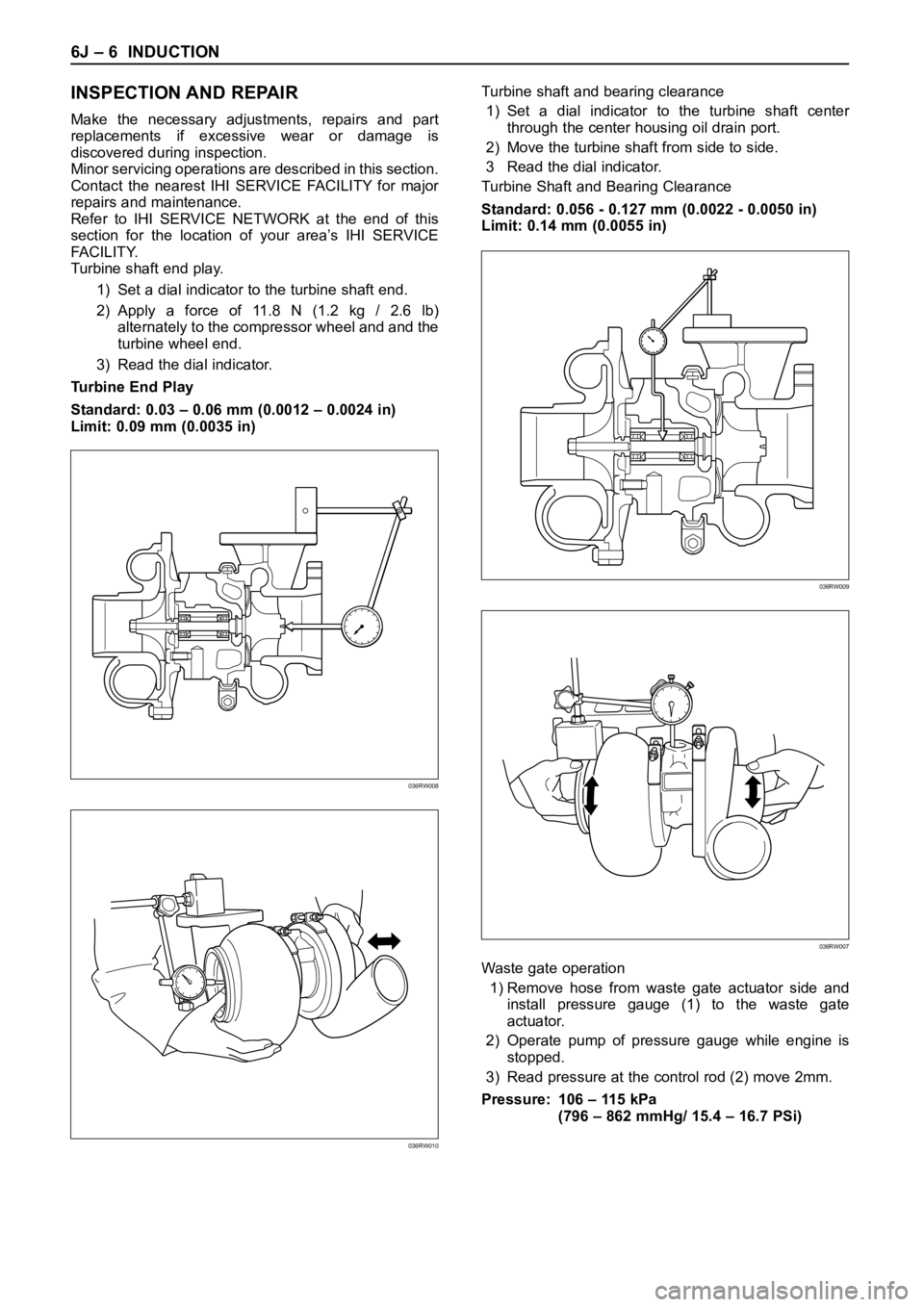
Turbine shaft end play.
1) Set a dial indicator to the turbine shaft end.
2) Apply a force of 11.8 N (1.2 kg / 2.6 lb)
alternately to the compressor wheel and and the
turbine wheel end.
3) Read the dial indicator.
Turbine End Play
Standard: 0.03 – 0.06 mm (0.0012 – 0.0024 in)
Limit: 0.09 mm (0.0035 in)Turbine shaft and bearing clearance
1) Set a dial indicator to the turbine shaft center
through the center housing oil drain port.
2) Move the turbine shaft from side to side.
3 Read the dial indicator.
Turbine Shaft and Bearing Clearance
Standard: 0.056 - 0.127 mm (0.0022 - 0.0050 in)
Limit: 0.14 mm (0.0055 in)
Waste gate operation
1) Remove hose from waste gate actuator side and
install pressure gauge (1) to the waste gate
actuator.
2) Operate pump of pressure gauge while engine is
stopped.
3) Read pressure at the control rod (2) move 2mm.
Pressure: 106 – 115 kPa
(796 – 862 mmHg/ 15.4 – 16.7 PSi)
036RW008
036RW010
036RW009
036RW007
Page 2164 of 6000
7A–10
AUTOMATIC TRANSMISSION (4L30–E)
Checking Transmission Fluid Level
and Condition
Checking fluid level and condition (color and odor) at
regular intervals will provide early diagnosis information
about the transmission. This information may be used to
correct a condition that, if not detected early, could result
in major transmission repairs.
IMPORTANT:When new, automatic transmission fluid
is red in color. As the vehicle is driven, the transmission
fluid will begin to look darker in color. The color may
eventually appear light brown.
A dark brown color with burnt odor may indicate
excessive fluid deterioration and signal a need for fluid
change.
Fluid Level
When adding or changing fluid, use only DEXRON –III.
Refer to Maintenance and Lubrication in General
Information section for maintenance information and
servicing interval.
CAUTION: DO NOT OVERFILL.
Overfilling will cause foaming, loss of fluid, abnor-
mal shifting and possible damage to the transmis-
sion.
1. Park the vehicle on level ground and apply the parking
brake firmly.
2. Check fluid level with engine running at idle.
NOTE: Be sure that transmission fluid temperature is
below 30
C (86F).
3. Move the selector lever through all gear ranges.
4. Move the selector lever to “Park”.
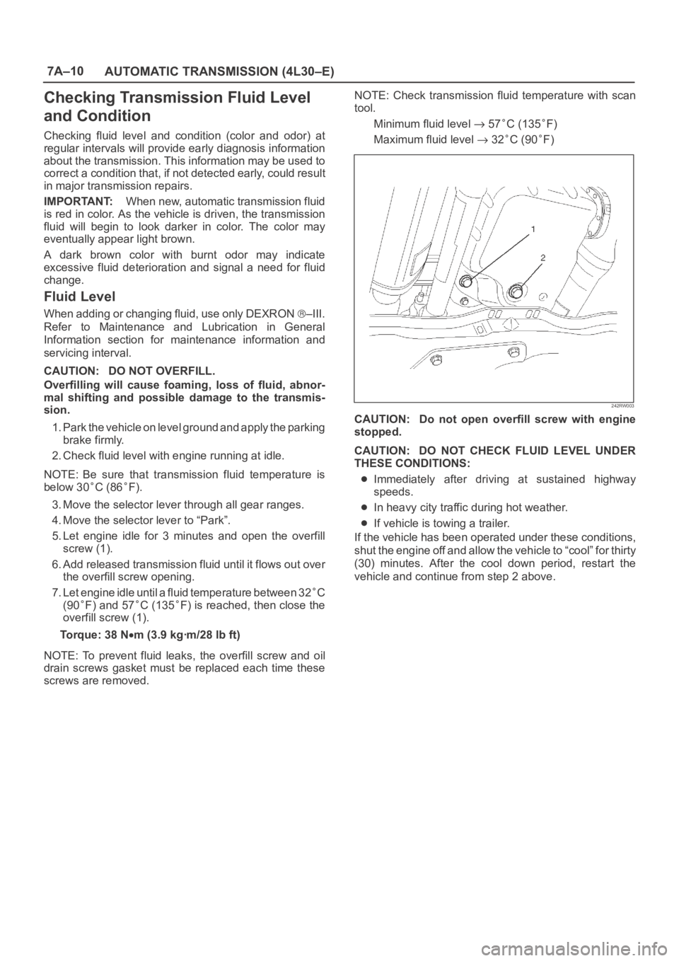
5. Let engine idle for 3 minutes and open the overfill
screw (1).
6. Add released transmission fluid until it flows out over
the overfill screw opening.
7. Let engine idle until a fluid temperature between 32
C
(90
F) and 57C (135F) is reached, then close the
overfill screw (1).
Torque: 38 N
m (3.9 kgꞏm/28 lb ft)
NOTE: To prevent fluid leaks, the overfill screw and oil
drain screws gasket must be replaced each time these
screws are removed.NOTE: Check transmission fluid temperature with scan
tool.
Minimum fluid level
57C (135F)
Maximum fluid level
32C (90F)
242RW003
CAUTION: Do not open overfill screw with engine
stopped.
CAUTION: DO NOT CHECK FLUID LEVEL UNDER
THESE CONDITIONS:
Immediately after driving at sustained highway
speeds.
In heavy city traffic during hot weather.
If vehicle is towing a trailer.
If the vehicle has been operated under these conditions,
shut the engine off and allow the vehicle to “cool” for thirty
(30) minutes. After the cool down period, restart the
vehicle and continue from step 2 above.
Page 2165 of 6000
7A–11 AUTOMATIC TRANSMISSION (4L30–E)
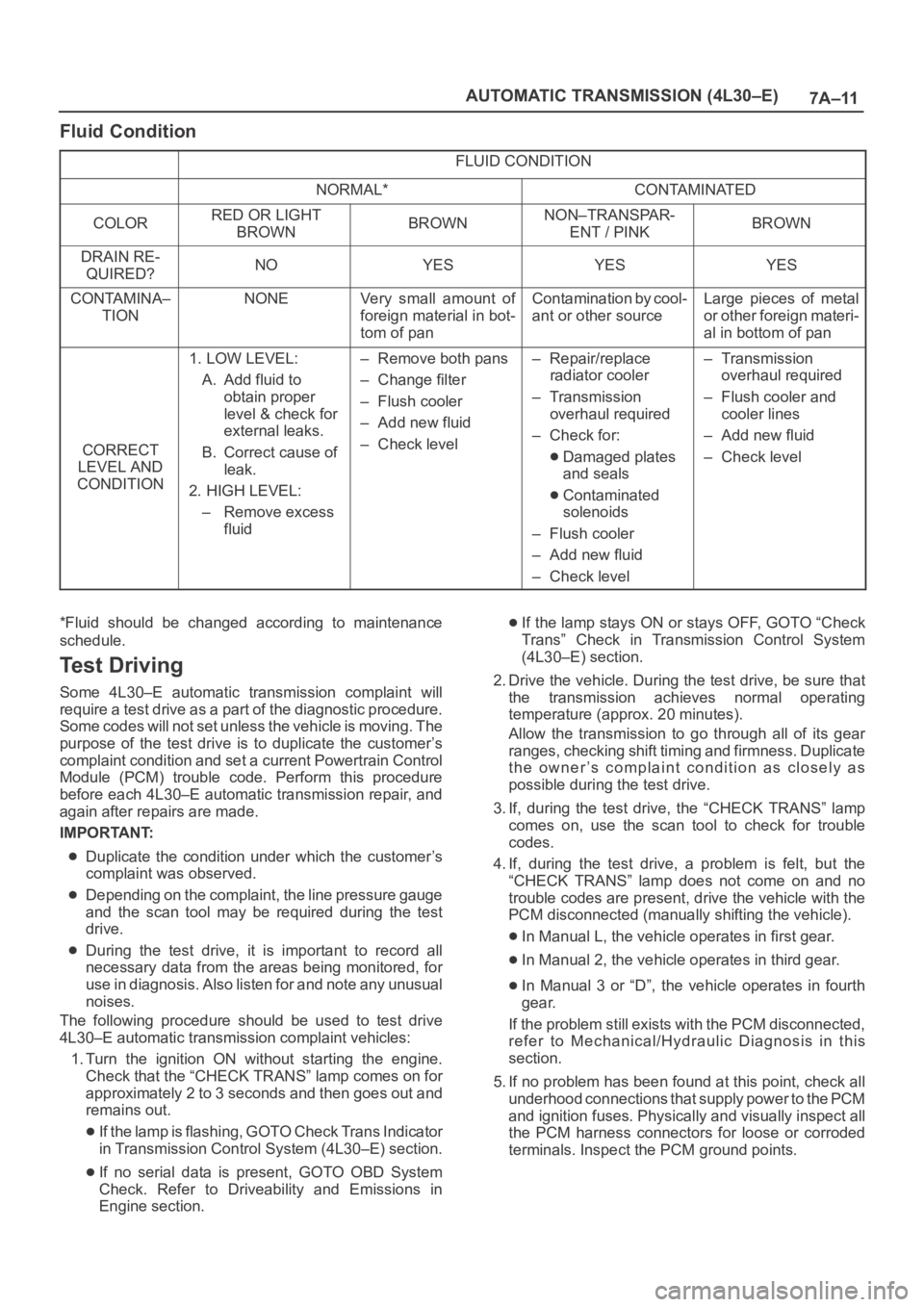
Fluid Condition
FLUID CONDITION
NORMAL*CONTAMINATED
COLORRED OR LIGHT
BROWNBROWNNON–TRANSPAR-
ENT / PINKBROWN
DRAIN RE-
QUIRED?NOYESYESYES
CONTAMINA–
TIONNONEVery small amount of
foreign material in bot-
tom of panContamination by cool-
ant or other sourceLarge pieces of metal
or other foreign materi-
al in bottom of pan
CORRECT
LEVEL AND
CONDITION
1. LOW LEVEL:
A. Add fluid to
obtain proper
level & check for
external leaks.
B. Correct cause of
leak.
2. HIGH LEVEL:
– Remove excess
fluid– Remove both pans
– Change filter
– Flush cooler
– Add new fluid
– Check level– Repair/replace
radiator cooler
–Transmission
overhaul required
– Check for:
Damaged plates
and seals
Contaminated
solenoids
– Flush cooler
– Add new fluid
– Check level
–Transmission
overhaul required
– Flush cooler and
cooler lines
– Add new fluid
– Check level
*Fluid should be changed according to maintenance
schedule.
Te s t D r i v i n g
Some 4L30–E automatic transmission complaint will
require a test drive as a part of the diagnostic procedure.
Some codes will not set unless the vehicle is moving. The
purpose of the test drive is to duplicate the customer’s
complaint condition and set a current Powertrain Control
Module (PCM) trouble code. Perform this procedure
before each 4L30–E automatic transmission repair, and
again after repairs are made.
IMPORTANT:
Duplicate the condition under which the customer’s
complaint was observed.
Depending on the complaint, the line pressure gauge
and the scan tool may be required during the test
drive.
During the test drive, it is important to record all
necessary data from the areas being monitored, for
use in diagnosis. Also listen for and note any unusual
noises.
The following procedure should be used to test drive
4L30–E automatic transmission complaint vehicles:
1. Turn the ignition ON without starting the engine.
Check that the “CHECK TRANS” lamp comes on for
approximately 2 to 3 seconds and then goes out and
remains out.
If the lamp is flashing, GOTO Check Trans Indicator
in Transmission Control System (4L30–E) section.
If no serial data is present, GOTO OBD System
Check. Refer to Driveability and Emissions in
Engine section.
If the lamp stays ON or stays OFF, GOTO “Check
Trans” Check in Transmission Control System
(4L30–E) section.
2. Drive the vehicle. During the test drive, be sure that
the transmission achieves normal operating
temperature (approx. 20 minutes).
Allow the transmission to go through all of its gear
ranges, checking shift timing and firmness. Duplicate
the owner’s complaint condition as closely as
possible during the test drive.
3. If, during the test drive, the “CHECK TRANS” lamp
comes on, use the scan tool to check for trouble
codes.
4. If, during the test drive, a problem is felt, but the
“CHECK TRANS” lamp does not come on and no
trouble codes are present, drive the vehicle with the
PCM disconnected (manually shifting the vehicle).
In Manual L, the vehicle operates in first gear.
In Manual 2, the vehicle operates in third gear.
In Manual 3 or “D”, the vehicle operates in fourth
gear.
If the problem still exists with the PCM disconnected,
refer to Mechanical/Hydraulic Diagnosis in this
section.
5. If no problem has been found at this point, check all
underhood connections that supply power to the PCM
and ignition fuses. Physically and visually inspect all
the PCM harness connectors for loose or corroded
terminals. Inspect the PCM ground points.
Page 3560 of 6000
PAGE NEXT
THIS MALUAL INCLUDES THE FOLLOWING SECTIONS:
SECTION No. CONTRNTS
0A GENERAL INFORMATION
0B MAINTENANCE AND LUBRICATION
HOME
0A
0B
Page 4099 of 6000
DRIVE LINE CONTROL SYSTEM (TOD) 4B2–16
7. Slowly start the vehicle in the 4L mode, and
accelerate to at least 20 km/h. Apply the brake to
completely stop the vehicle.
If the CHECK lamp starts blinking during the test run, read
the trouble codes and give appropriate maintenance
according to the diagnostic procedure. If the TOD
indicator lamps are lit abnormally during the run, check
the lighting condition and give appropriate maintenance
according to the diagnostic procedure. Even if the
phenomena are not observed, try to reproduce the
abnormal state reported by the customer to the possible
extent.
Post-Repair Check
As long as the starter is not turned off, the TOD indicator
lamps continue blinking even after the failed portion
repaired. Therefore, upon completion of repair, be sure to
turn off the starter switch once and then turn on it to
conduct the test run sequence specified in steps 1
through 7 above and check that the TOD indicator lamps
no longer show any faulty status.
Page 4208 of 6000
4C–2
DRIVE SHAFT SYSTEM
Service Precaution
WARNING: IF SO EQUIPPED WITH A
SUPPLEMENTAL RESTRAINT SYSTEM (SRS),
REFER TO THE SRS COMPONENT AND WIRING
LOCATION VIEW IN ORDER TO DETERMINE
WHETHER YOU ARE PERFORMING SERVICE ON OR
NEAR THE SRS COMPONENTS OR THE SRS
WIRING. WHEN YOU ARE PERFORMING SERVICE
ON OR NEAR THE SRS COMPONENTS OR THE SRS
WIRING, REFER TO THE SRS SERVICE
INFORMATION. FAILURE TO FOLLOW WARNINGS
COULD RESULT IN POSSIBLE AIR BAG
DEPLOYMENT, PERSONAL INJURY, OR
OTHERWISE UNNEEDED SRS SYSTEM REPAIRS.
CAUTION: Always use the correct fastener in the
proper location. When you replace a fastener, use
ONLY the exact part number for that application.
ISUZU will call out those fasteners that require a
replacement after removal. ISUZU will also call out
the fasteners that require thread lockers or thread
sealant. UNLESS OTHERWISE SPECIFIED , do not
use supplemental coatings (Paints, greases, or other
corrosion inhibitors) on threaded fasteners or
fastener joint interfaces. Generally, such coatings
adversely affect the fastener torque and the joint
clamping force, and may damage the fastener. When
you install fasteners, use the correct tightening
sequence and specifications. Following these
instructions can help you avoid damage to parts and
systems.
General Description
This publication contains essential removal, installation,
adjustment and maintenance procedures.
The front axle utilizes a central disconnect type front
axle/transfer case system.
The drive axles are completely flexible assemblies,
consisting of inner and outer constant velocity (CV) drive
shaft joints connected by an axle shaft.
For description of propeller shaft and universal joint, refer
to Front/Rear Propeller Shaft in this section.
Page 4512 of 6000
6A–16
ENGINE MECHANICAL
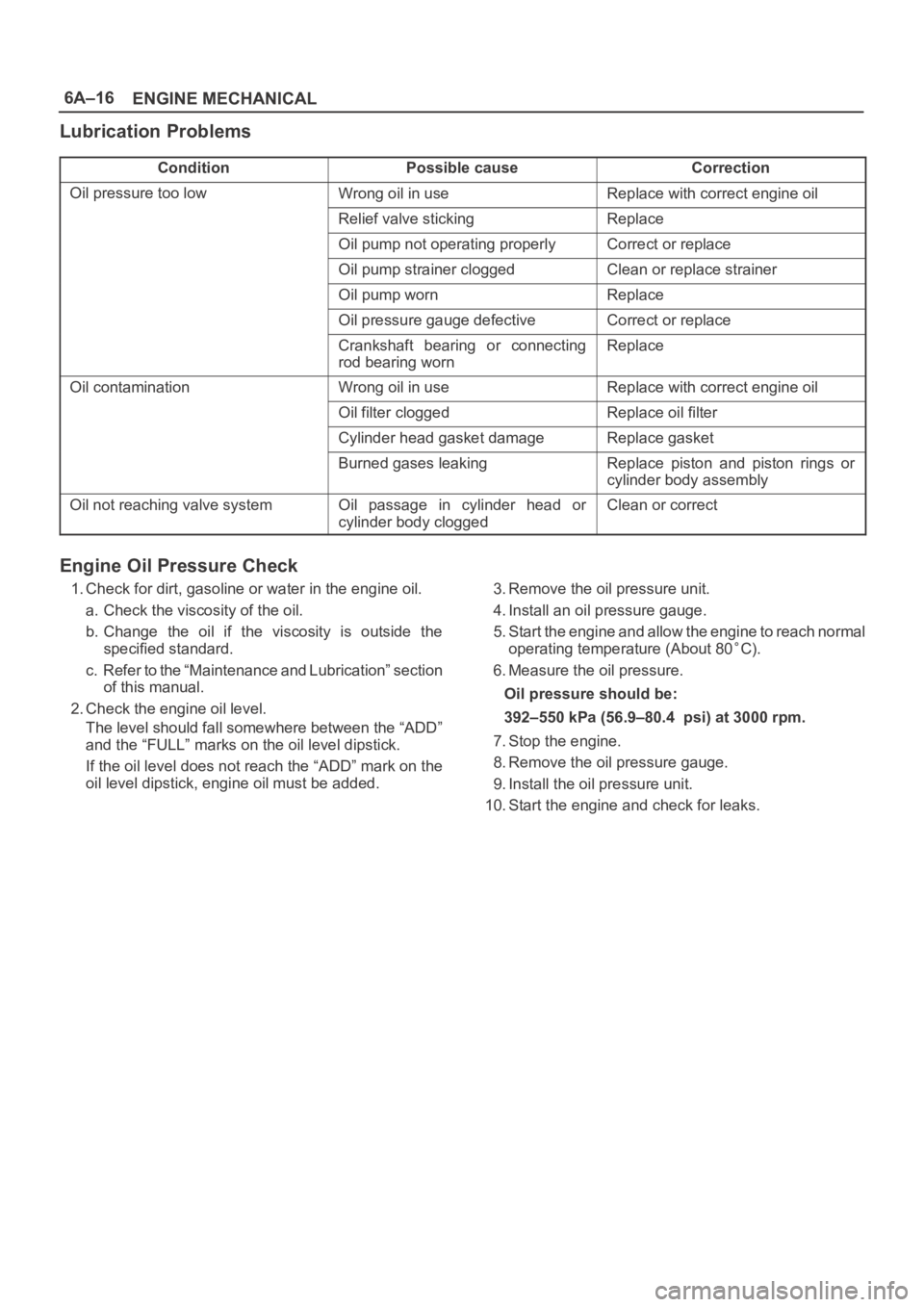
Lubrication Problems
ConditionPossible causeCorrection
Oil pressure too lowWrong oil in useReplace with correct engine oil
Relief valve stickingReplace
Oil pump not operating properlyCorrect or replace
Oil pump strainer cloggedClean or replace strainer
Oil pump wornReplace
Oil pressure gauge defectiveCorrect or replace
Crankshaft bearing or connecting
rod bearing wornReplace
Oil contaminationWrong oil in useReplace with correct engine oil
Oil filter cloggedReplace oil filter
Cylinder head gasket damageReplace gasket
Burned gases leakingReplace piston and piston rings or
cylinder body assembly
Oil not reaching valve systemOil passage in cylinder head or
cylinder body cloggedClean or correct
Engine Oil Pressure Check
1. Check for dirt, gasoline or water in the engine oil.
a. Check the viscosity of the oil.
b. Change the oil if the viscosity is outside the
specified standard.
c. Refer to the “Maintenance and Lubrication” section
of this manual.
2. Check the engine oil level.
The level should fall somewhere between the “ADD”
and the “FULL” marks on the oil level dipstick.
If the oil level does not reach the “ADD” mark on the
oil level dipstick, engine oil must be added.3. Remove the oil pressure unit.
4. Install an oil pressure gauge.
5. Start the engine and allow the engine to reach normal
operating temperature (About 80
C).
6. Measure the oil pressure.
Oil pressure should be:
392–550 kPa (56.9–80.4 psi) at 3000 rpm.
7. Stop the engine.
8. Remove the oil pressure gauge.
9. Install the oil pressure unit.
10. Start the engine and check for leaks.
Page 4612 of 6000
6C–5
ENGINE FUEL
Installation
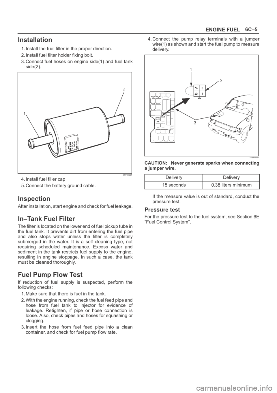
1. Install the fuel filter in the proper direction.
2. Install fuel filter holder fixing bolt.
3. Connect fuel hoses on engine side(1) and fuel tank
side(2).
041RW001
4. Install fuel filler cap
5. Connect the battery ground cable.
Inspection
After installation, start engine and check for fuel leakage.
In–Tank Fuel Filter
The filter is located on the lower end of fuel pickup tube in
the fuel tank. It prevents dirt from entering the fuel pipe
and also stops water unless the filter is completely
submerged in the water. It is a self cleaning type, not
requiring scheduled maintenance. Excess water and
sediment in the tank restricts fuel supply to the engine,
resulting in engine stoppage. In such a case, the tank
must be cleaned thoroughly.
Fuel Pump Flow Test
If reduction of fuel supply is suspected, perform the
following checks:
1. Make sure that there is fuel in the tank.
2. With the engine running, check the fuel feed pipe and
hose from fuel tank to injector for evidence of
leakage. Retighten, if pipe or hose connection is
loose. Also, check pipes and hoses for squashing or
clogging.
3. Insert the hose from fuel feed pipe into a clean
container, and check for fuel pump flow rate.4. Connect the pump relay terminals with a jumper
wire(1) as shown and start the fuel pump to measure
delivery.
140RW002
CAUTION: Never generate sparks when connecting
a jumper wire.
Delivery
Delivery
15 seconds0.38 liters minimum
If the measure value is out of standard, conduct the
pressure test.
Pressure test
For the pressure test to the fuel system, see Section 6E
“Fuel Control System”.