Page 5719 of 6000

7A–30
AUTOMATIC TRANSMISSION (4L30–E)
Removal
1. Disconnect battery ground cable.
2. Remove transfer control lever knob.
3. Remove front console.
Disconnect wiring harness connectors from front
console.
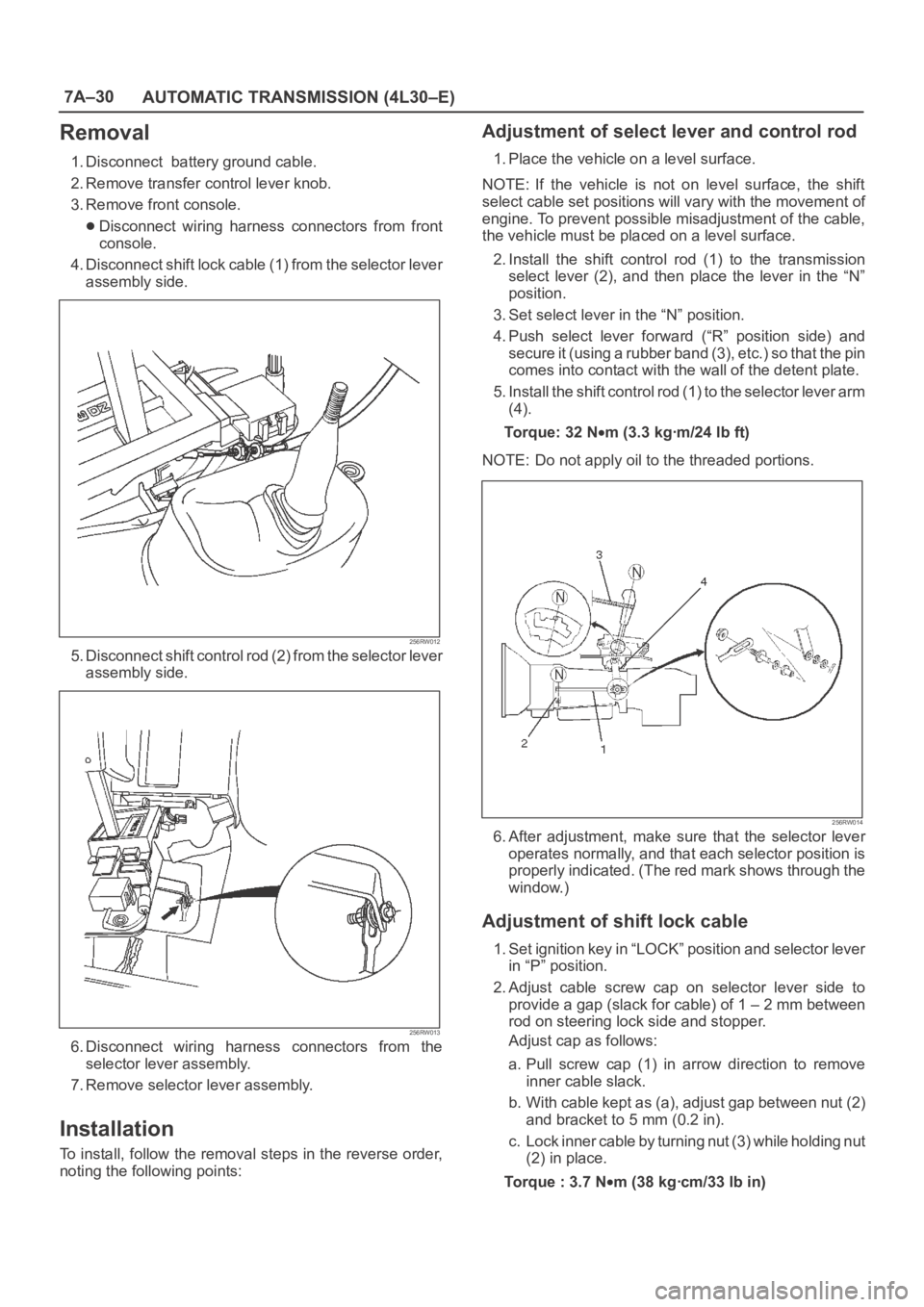
4. Disconnect shift lock cable (1) from the selector lever
assembly side.
256RW012
5. Disconnect shift control rod (2) from the selector lever
assembly side.
256RW013
6. Disconnect wiring harness connectors from the
selector lever assembly.
7. Remove selector lever assembly.
Installation
To install, follow the removal steps in the reverse order,
noting the following points:
Adjustment of select lever and control rod
1. Place the vehicle on a level surface.
NOTE: If the vehicle is not on level surface, the shift
select cable set positions will vary with the movement of
engine. To prevent possible misadjustment of the cable,
the vehicle must be placed on a level surface.
2. Install the shift control rod (1) to the transmission
select lever (2), and then place the lever in the “N”
position.
3. Set select lever in the “N” position.
4. Push select lever forward (“R” position side) and
s e c u r e i t ( u s i n g a r u b b e r b a n d ( 3 ) , e t c . ) s o t h a t t h e p i n
comes into contact with the wall of the detent plate.
5. Install the shift control rod (1) to the selector lever arm
(4).
To r q u e : 3 2 N
m (3.3 kgꞏm/24 lb ft)
NOTE: Do not apply oil to the threaded portions.
256RW014
6. After adjustment, make sure that the selector lever
operates normally, and that each selector position is
properly indicated. (The red mark shows through the
window.)
Adjustment of shift lock cable
1. Set ignition key in “LOCK” position and selector lever
in “P” position.
2. Adjust cable screw cap on selector lever side to
provide a gap (slack for cable) of 1 – 2 mm between
rod on steering lock side and stopper.
Adjust cap as follows:
a. Pull screw cap (1) in arrow direction to remove
inner cable slack.
b. With cable kept as (a), adjust gap between nut (2)
and bracket to 5 mm (0.2 in).
c. Lock inner cable by turning nut (3) while holding nut
(2) in place.
Torque : 3.7 N
m (38 kgꞏcm/33 lb in)
Page 5860 of 6000

AUTOMATIC TRANSMISSION (AW30-40LE) 7A–79
244RY00005
101RY00004
249RW003
242RW013
Look-up solenoid (Normal open type)
THROTTLE POSITION SENSOR
INSPECTION
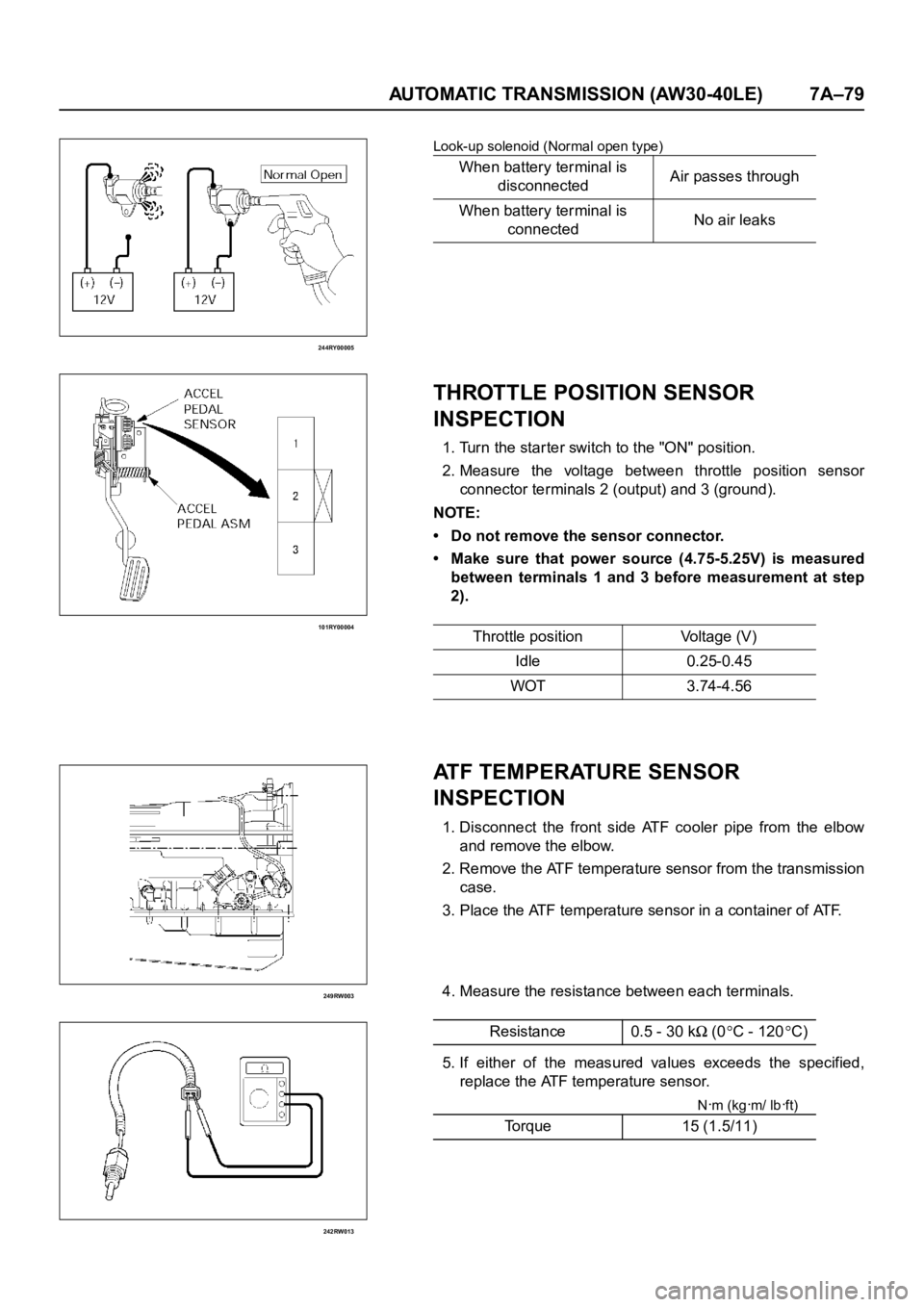
1. Turn the starter switch to the "ON" position.
2. Measure the voltage between throttle position sensor
connector terminals 2 (output) and 3 (ground).
NOTE:
• Do not remove the sensor connector.
• Make sure that power source (4.75-5.25V) is measured
between terminals 1 and 3 before measurement at step
2).
ATF TEMPERATURE SENSOR
INSPECTION
1. Disconnect the front side ATF cooler pipe from the elbow
and remove the elbow.
2. Remove the ATF temperature sensor from the transmission
case.
3. Place the ATF temperature sensor in a container of ATF.
4. Measure the resistance between each terminals.
5. If either of the measured values exceeds the specified,
replace the ATF temperature sensor.
Nꞏm (kgꞏm/ lbꞏft)
When battery terminal is
disconnectedAir passes through
When battery terminal is
connectedNo air leaks
Throttle position Voltage (V)
Idle 0.25-0.45
WOT 3.74-4.56
Resistance 0.5 - 30 k
(0C - 120C)
Torque 15 (1.5/11)
Page 5861 of 6000
7A–80 AUTOMATIC TRANSMISSION (AW30-40LE)
256RY00001
256RW012
256RW013
SELECTOR LEVER
INSPECTION
1. Make sure that when the selector lever is shifted from "P" to
"L", a "clicking" can be felt at each shift position. Make sure
that the gear corresponds to that of the position plate
indicator.
2. Check to see if the shifter lever can be shifted as shown.
REMOVAL
Preparation:
Diconnect negative (–) battery cable.
1. Transfer Control Lever Knob
2. Front Console
Disconnect wiring harness connectors.
3. Selector Lever Assembly
1) Disconnect shift lock cable from the selector lever
assembly side.
2) Disconnect wiring harness connectors.
3) Disconnect shift control rod from the selector lever
assembly side.
Page 5869 of 6000
7A–88 AUTOMATIC TRANSMISSION (AW30-40LE)
240RY00026
022RY00001
11. Under cover and flex plate-torque converter bolt
• Remove the under cover.
• Turn the crankshaft to gain access to each bolt.
Remove the six torque cover ter fixing bolts.
NOTE:
New fixing bolts should be replaced for reassembly.
12. Rear mounting nut
• Support transmission with a jack.
• Remove two rear mounting nuts from the 3rd
crossmember.
13. 3rd crossmember
14. Oil level gauge and tube
15. Starter
• Remove the mounting bolts, and pull the star ter toward
the front of the vehicle.
Lay the star ter alongside the engine.
16. Engine-transmission bolt
• Remove engine-transmission fixing bolts.
• Disconnect the breather hose from the breather hose 3
way (W/TOD) or 2 way (WO/TOD).
17. Transmission assembly
NOTE:
Keep the oil pan positioned down.
Be careful not to let the torque converter slide out.