1998 OPEL FRONTERA light
[x] Cancel search: lightPage 2103 of 6000
6E–210
4JX1–TC ENGINE DRIVEABILITY AND EMISSIONS
Vehicle Speed Sensor (VSS)
Removal Procedure
CAUTION: The VSS is located on the right side of
the transfer case just ahead of the rear propeller
shaft and very close to the exhaust pipes. Be sure
that the exhaust pipes are cool enough to touch
before trying to remove the VSS. If the pipes are hot,
you could be burned.
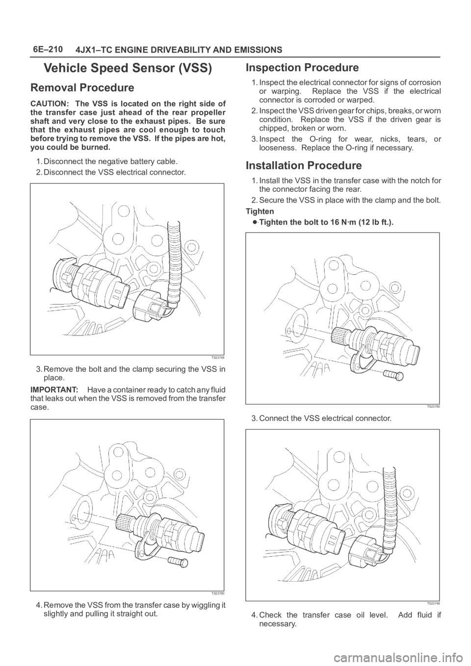
1. Disconnect the negative battery cable.
2. Disconnect the VSS electrical connector.
TS23748
3. Remove the bolt and the clamp securing the VSS in
place.
IMPORTANT:H a v e a c o n t a i n e r r e a d y t o c a t c h a n y f l u i d
that leaks out when the VSS is removed from the transfer
case.
TS23780
4. Remove the VSS from the transfer case by wiggling it
slightly and pulling it straight out.
Inspection Procedure
1. Inspect the electrical connector for signs of corrosion
or warping. Replace the VSS if the electrical
connector is corroded or warped.
2. Inspect the VSS driven gear for chips, breaks, or worn
condition. Replace the VSS if the driven gear is
chipped, broken or worn.
3. Inspect the O-ring for wear, nicks, tears, or
looseness. Replace the O-ring if necessary.
Installation Procedure
1. Install the VSS in the transfer case with the notch for
the connector facing the rear.
2. Secure the VSS in place with the clamp and the bolt.
Tighten
Tighten the bolt to 16 Nꞏm (12 lb ft.).
TS23780
3. Connect the VSS electrical connector.
TS23748
4. Check the transfer case oil level. Add fluid if
necessary.
Page 2119 of 6000
6E–226
4JX1–TC ENGINE DRIVEABILITY AND EMISSIONS
0018
Manifold Absolute Pressure (MAP) Sensor
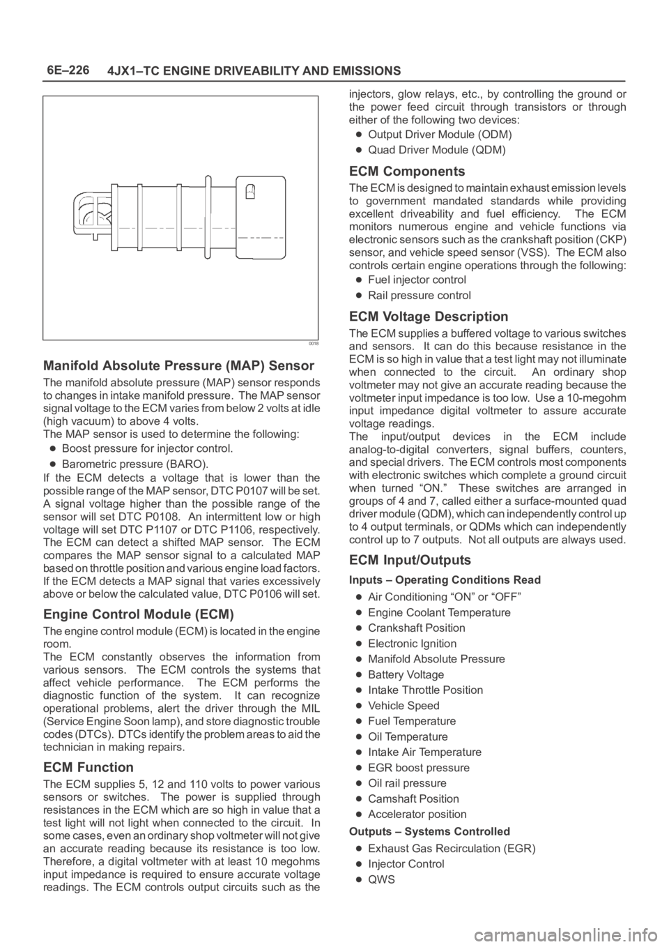
The manifold absolute pressure (MAP) sensor responds
to changes in intake manifold pressure. The MAP sensor
signal voltage to the ECM varies from below 2 volts at idle
(high vacuum) to above 4 volts.
The MAP sensor is used to determine the following:
Boost pressure for injector control.
Barometric pressure (BARO).
If the ECM detects a voltage that is lower than the
possible range of the MAP sensor, DTC P0107 will be set.
A signal voltage higher than the possible range of the
sensor will set DTC P0108. An intermittent low or high
voltage will set DTC P1107 or DTC P1106, respectively.
The ECM can detect a shifted MAP sensor. The ECM
compares the MAP sensor signal to a calculated MAP
based on throttle position and various engine load factors.
If the ECM detects a MAP signal that varies excessively
above or below the calculated value, DTC P0106 will set.
Engine Control Module (ECM)
The engine control module (ECM) is located in the engine
room.
The ECM constantly observes the information from
various sensors. The ECM controls the systems that
affect vehicle performance. The ECM performs the
diagnostic function of the system. It can recognize
operational problems, alert the driver through the MIL
(Service Engine Soon lamp), and store diagnostic trouble
codes (DTCs). DTCs identify the problem areas to aid the
technician in making repairs.
ECM Function
The ECM supplies 5, 12 and 110 volts to power various
sensors or switches. The power is supplied through
resistances in the ECM which are so high in value that a
test light will not light when connected to the circuit. In
some cases, even an ordinary shop voltmeter will not give
an accurate reading because its resistance is too low.
Therefore, a digital voltmeter with at least 10 megohms
input impedance is required to ensure accurate voltage
readings. The ECM controls output circuits such as theinjectors, glow relays, etc., by controlling the ground or
the power feed circuit through transistors or through
either of the following two devices:
Output Driver Module (ODM)
Quad Driver Module (QDM)
ECM Components
The ECM is designed to maintain exhaust emission levels
to government mandated standards while providing
excellent driveability and fuel efficiency. The ECM
monitors numerous engine and vehicle functions via
electronic sensors such as the crankshaft position (CKP)
sensor, and vehicle speed sensor (VSS). The ECM also
controls certain engine operations through the following:
Fuel injector control
Rail pressure control
ECM Voltage Description
The ECM supplies a buffered voltage to various switches
and sensors. It can do this because resistance in the
ECM is so high in value that a test light may not illuminate
when connected to the circuit. An ordinary shop
voltmeter may not give an accurate reading because the
voltmeter input impedance is too low. Use a 10-megohm
input impedance digital voltmeter to assure accurate
voltage readings.
The input/output devices in the ECM include
analog-to-digital converters, signal buffers, counters,
and special drivers. The ECM controls most components
with electronic switches which complete a ground circuit
when turned “ON.” These switches are arranged in
groups of 4 and 7, called either a surface-mounted quad
driver module (QDM), which can independently control up
to 4 output terminals, or QDMs which can independently
control up to 7 outputs. Not all outputs are always used.
ECM Input/Outputs
Inputs – Operating Conditions Read
Air Conditioning “ON” or “OFF”
Engine Coolant Temperature
Crankshaft Position
Electronic Ignition
Manifold Absolute Pressure
Battery Voltage
Intake Throttle Position
Vehicle Speed
Fuel Temperature
Oil Temperature
Intake Air Temperature
EGR boost pressure
Oil rail pressure
Camshaft Position
Accelerator position
Outputs – Systems Controlled
Exhaust Gas Recirculation (EGR)
Injector Control
QWS
Page 2164 of 6000
7A–10
AUTOMATIC TRANSMISSION (4L30–E)
Checking Transmission Fluid Level
and Condition
Checking fluid level and condition (color and odor) at
regular intervals will provide early diagnosis information
about the transmission. This information may be used to
correct a condition that, if not detected early, could result
in major transmission repairs.
IMPORTANT:When new, automatic transmission fluid
is red in color. As the vehicle is driven, the transmission
fluid will begin to look darker in color. The color may
eventually appear light brown.
A dark brown color with burnt odor may indicate
excessive fluid deterioration and signal a need for fluid
change.
Fluid Level
When adding or changing fluid, use only DEXRON –III.
Refer to Maintenance and Lubrication in General
Information section for maintenance information and
servicing interval.
CAUTION: DO NOT OVERFILL.
Overfilling will cause foaming, loss of fluid, abnor-
mal shifting and possible damage to the transmis-
sion.
1. Park the vehicle on level ground and apply the parking
brake firmly.
2. Check fluid level with engine running at idle.
NOTE: Be sure that transmission fluid temperature is
below 30
C (86F).
3. Move the selector lever through all gear ranges.
4. Move the selector lever to “Park”.
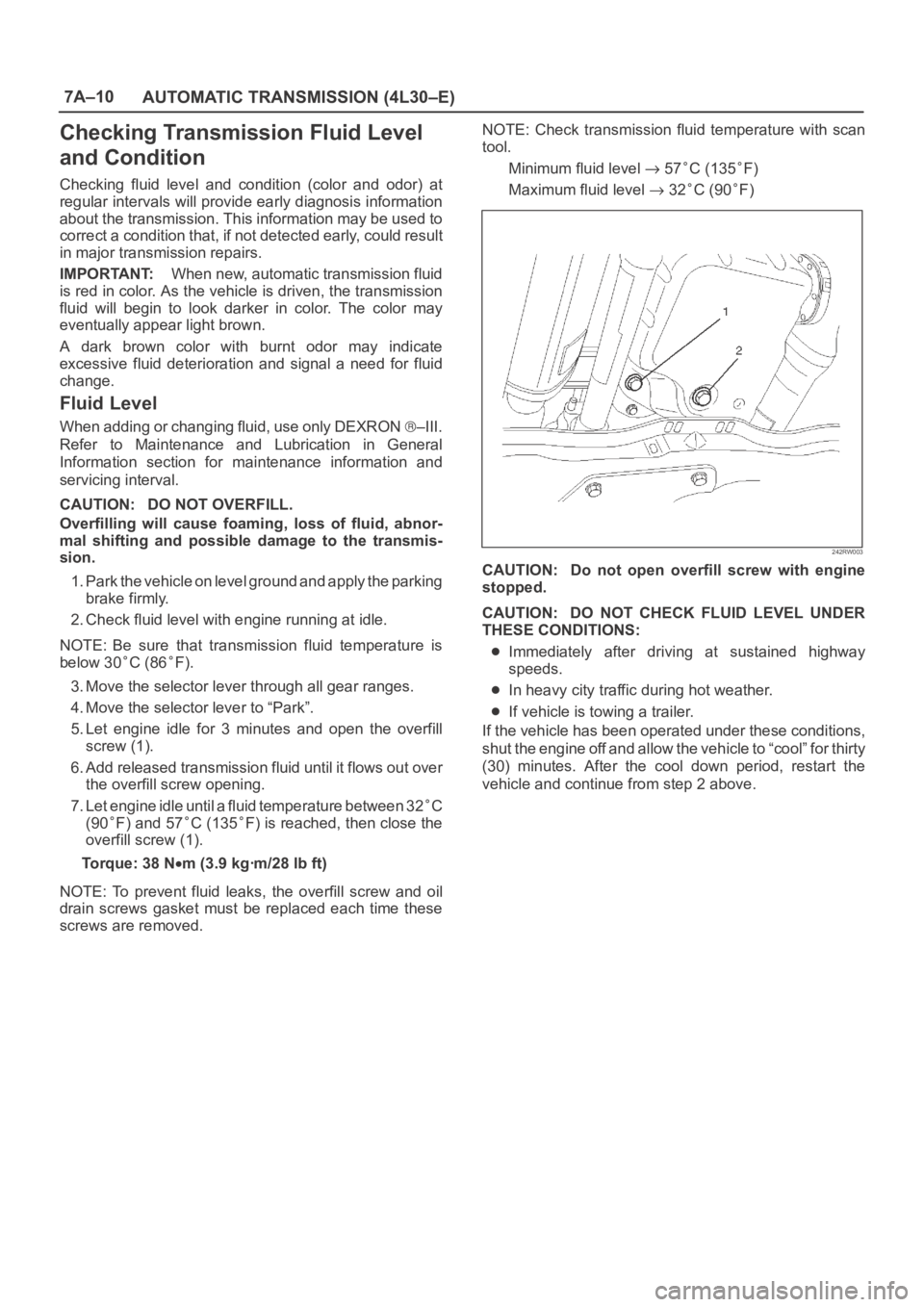
5. Let engine idle for 3 minutes and open the overfill
screw (1).
6. Add released transmission fluid until it flows out over
the overfill screw opening.
7. Let engine idle until a fluid temperature between 32
C
(90
F) and 57C (135F) is reached, then close the
overfill screw (1).
Torque: 38 N
m (3.9 kgꞏm/28 lb ft)
NOTE: To prevent fluid leaks, the overfill screw and oil
drain screws gasket must be replaced each time these
screws are removed.NOTE: Check transmission fluid temperature with scan
tool.
Minimum fluid level
57C (135F)
Maximum fluid level
32C (90F)
242RW003
CAUTION: Do not open overfill screw with engine
stopped.
CAUTION: DO NOT CHECK FLUID LEVEL UNDER
THESE CONDITIONS:
Immediately after driving at sustained highway
speeds.
In heavy city traffic during hot weather.
If vehicle is towing a trailer.
If the vehicle has been operated under these conditions,
shut the engine off and allow the vehicle to “cool” for thirty
(30) minutes. After the cool down period, restart the
vehicle and continue from step 2 above.
Page 2165 of 6000
7A–11 AUTOMATIC TRANSMISSION (4L30–E)
Fluid Condition
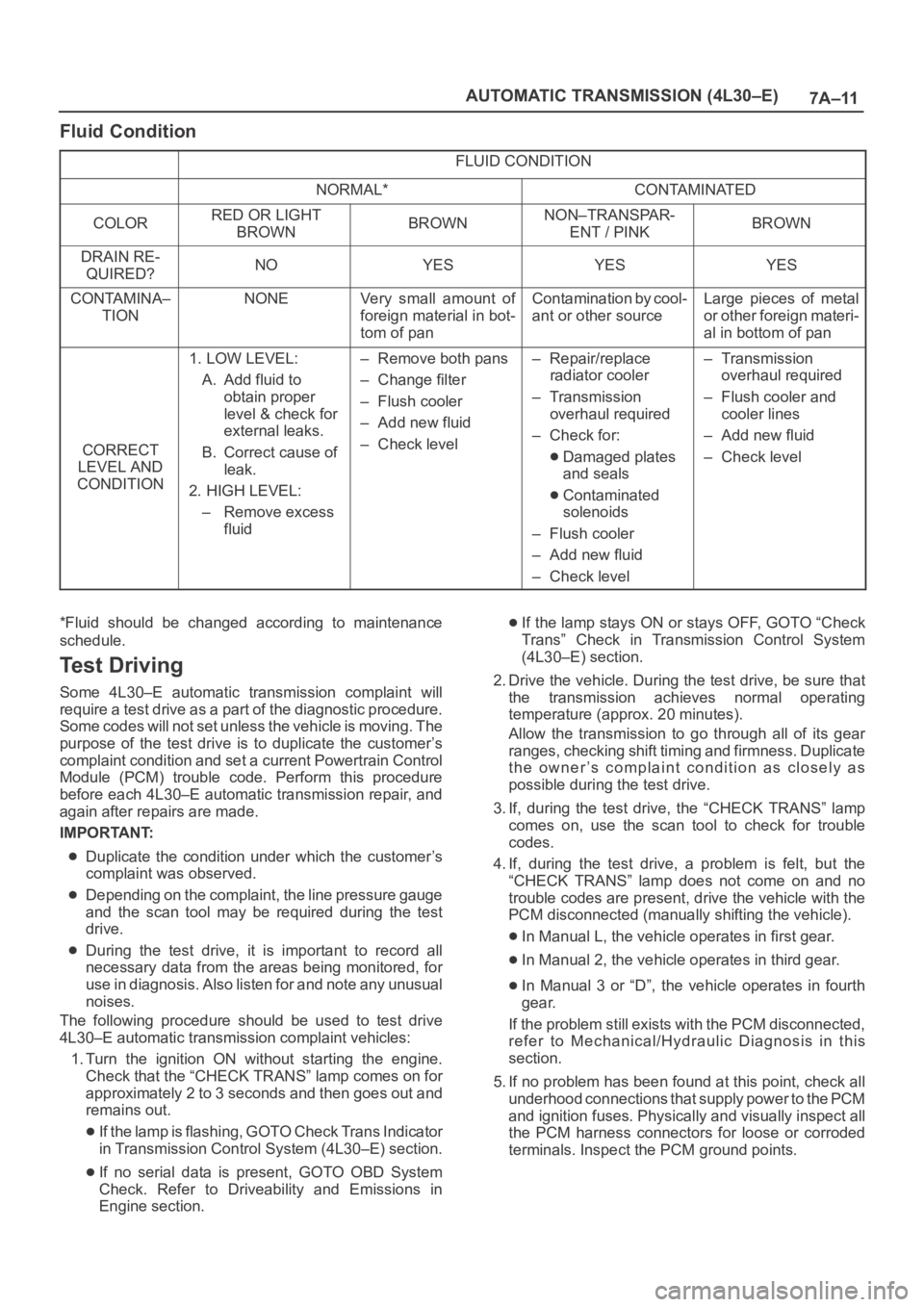
FLUID CONDITION
NORMAL*CONTAMINATED
COLORRED OR LIGHT
BROWNBROWNNON–TRANSPAR-
ENT / PINKBROWN
DRAIN RE-
QUIRED?NOYESYESYES
CONTAMINA–
TIONNONEVery small amount of
foreign material in bot-
tom of panContamination by cool-
ant or other sourceLarge pieces of metal
or other foreign materi-
al in bottom of pan
CORRECT
LEVEL AND
CONDITION
1. LOW LEVEL:
A. Add fluid to
obtain proper
level & check for
external leaks.
B. Correct cause of
leak.
2. HIGH LEVEL:
– Remove excess
fluid– Remove both pans
– Change filter
– Flush cooler
– Add new fluid
– Check level– Repair/replace
radiator cooler
–Transmission
overhaul required
– Check for:
Damaged plates
and seals
Contaminated
solenoids
– Flush cooler
– Add new fluid
– Check level
–Transmission
overhaul required
– Flush cooler and
cooler lines
– Add new fluid
– Check level
*Fluid should be changed according to maintenance
schedule.
Te s t D r i v i n g
Some 4L30–E automatic transmission complaint will
require a test drive as a part of the diagnostic procedure.
Some codes will not set unless the vehicle is moving. The
purpose of the test drive is to duplicate the customer’s
complaint condition and set a current Powertrain Control
Module (PCM) trouble code. Perform this procedure
before each 4L30–E automatic transmission repair, and
again after repairs are made.
IMPORTANT:
Duplicate the condition under which the customer’s
complaint was observed.
Depending on the complaint, the line pressure gauge
and the scan tool may be required during the test
drive.
During the test drive, it is important to record all
necessary data from the areas being monitored, for
use in diagnosis. Also listen for and note any unusual
noises.
The following procedure should be used to test drive
4L30–E automatic transmission complaint vehicles:
1. Turn the ignition ON without starting the engine.
Check that the “CHECK TRANS” lamp comes on for
approximately 2 to 3 seconds and then goes out and
remains out.
If the lamp is flashing, GOTO Check Trans Indicator
in Transmission Control System (4L30–E) section.
If no serial data is present, GOTO OBD System
Check. Refer to Driveability and Emissions in
Engine section.
If the lamp stays ON or stays OFF, GOTO “Check
Trans” Check in Transmission Control System
(4L30–E) section.
2. Drive the vehicle. During the test drive, be sure that
the transmission achieves normal operating
temperature (approx. 20 minutes).
Allow the transmission to go through all of its gear
ranges, checking shift timing and firmness. Duplicate
the owner’s complaint condition as closely as
possible during the test drive.
3. If, during the test drive, the “CHECK TRANS” lamp
comes on, use the scan tool to check for trouble
codes.
4. If, during the test drive, a problem is felt, but the
“CHECK TRANS” lamp does not come on and no
trouble codes are present, drive the vehicle with the
PCM disconnected (manually shifting the vehicle).
In Manual L, the vehicle operates in first gear.
In Manual 2, the vehicle operates in third gear.
In Manual 3 or “D”, the vehicle operates in fourth
gear.
If the problem still exists with the PCM disconnected,
refer to Mechanical/Hydraulic Diagnosis in this
section.
5. If no problem has been found at this point, check all
underhood connections that supply power to the PCM
and ignition fuses. Physically and visually inspect all
the PCM harness connectors for loose or corroded
terminals. Inspect the PCM ground points.
Page 2184 of 6000
7A–30
AUTOMATIC TRANSMISSION (4L30–E)
249RW001
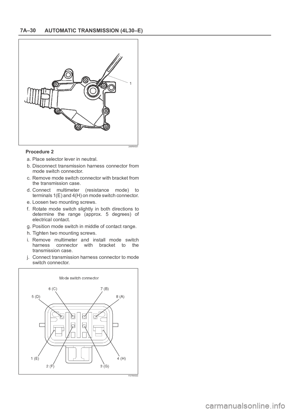
Procedure 2
a. Place selector lever in neutral.
b. Disconnect transmission harness connector from
mode switch connector.
c. Remove mode switch connector with bracket from
the transmission case.
d. Connect multimeter (resistance mode) to
terminals 1(E) and 4(H) on mode switch connector.
e. Loosen two mounting screws.
f. Rotate mode switch slightly in both directions to
determine the range (approx. 5 degrees) of
electrical contact.
g. Position mode switch in middle of contact range.
h. Tighten two mounting screws.
i. Remove multimeter and install mode switch
harness connector with bracket to the
transmission case.
j. Connect transmission harness connector to mode
switch connector.
F07RW003
Page 2201 of 6000
7A–47 AUTOMATIC TRANSMISSION (4L30–E)
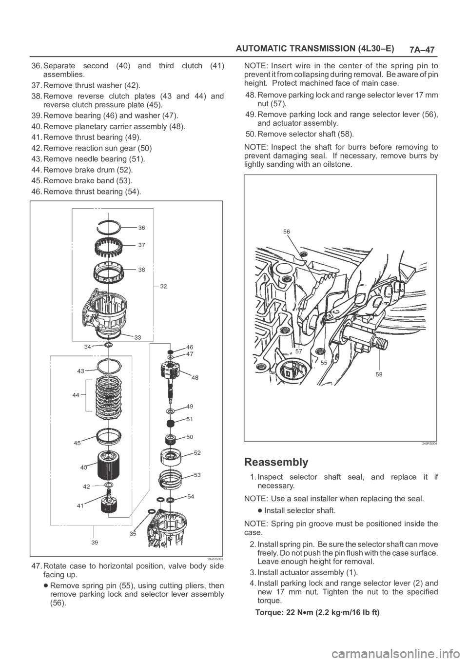
36. Separate second (40) and third clutch (41)
assemblies.
37. Remove thrust washer (42).
38. Remove reverse clutch plates (43 and 44) and
reverse clutch pressure plate (45).
39. Remove bearing (46) and washer (47).
40. Remove planetary carrier assembly (48).
41. Remove thrust bearing (49).
42. Remove reaction sun gear (50)
43. Remove needle bearing (51).
44. Remove brake drum (52).
45. Remove brake band (53).
46. Remove thrust bearing (54).
242RS003
47. Rotate case to horizontal position, valve body side
facing up.
Remove spring pin (55), using cutting pliers, then
remove parking lock and selector lever assembly
(56).NOTE: Insert wire in the center of the spring pin to
prevent it from collapsing during removal. Be aware of pin
height. Protect machined face of main case.
48. Remove parking lock and range selector lever 17 mm
nut (57).
49. Remove parking lock and range selector lever (56),
and actuator assembly.
50. Remove selector shaft (58).
NOTE: Inspect the shaft for burrs before removing to
prevent damaging seal. If necessary, remove burrs by
lightly sanding with an oilstone.
249RS004
Reassembly
1. Inspect selector shaft seal, and replace it if
necessary.
NOTE: Use a seal installer when replacing the seal.
Install selector shaft.
NOTE: Spring pin groove must be positioned inside the
case.
2. Install spring pin. Be sure the selector shaft can move
freely. Do not push the pin flush with the case surface.
Leave enough height for removal.
3. Install actuator assembly (1).
4. Install parking lock and range selector lever (2) and
new 17 mm nut. Tighten the nut to the specified
torque.
To r q u e : 2 2 N
m (2.2 kgꞏm/16 lb ft)
Page 2254 of 6000
TRANSMISSION CONTROL SYSTEM (4L30–E)7A1–9
Winter Drive Mode
1.Operation
The winter switch will operate when switched on after
all of the following conditions are present:
a. The gear select position is “D”, “N”, “R” and “P”
range.
b. Vehicle speed is 7 mph (11 km/h) or less.
c. Transmission oil temperature is 120
C (248F) or
less.
d. Kickdown switch is off.
e. Accelerator opening is at 8% or less.
2.Cancel Release
1. Cancellation by driver
a. Turning off the winter drive mode switch
b. Shifting select position to “3”, “2”, or “L” (Winter
drive mode is not canceled by selecting “D”, “N”,
“R”, or “P”)
c. Ignition key is turned off.
2. Automatic cancellation
a. When vehicle runs at 21mph (34 km/h) or more
for 1 second or more
b. When transmission oil temperature reaches
140
C (284F) or above
NOTE: The mode returns to normal drive mode or power
drive mode after the winter drive mode is canceled.
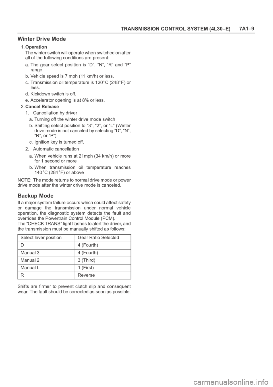
Backup Mode
If a major system failure occurs which could affect safety
or damage the transmission under normal vehicle
operation, the diagnostic system detects the fault and
overrides the Powertrain Control Module (PCM).
The “CHECK TRANS” light flashes to alert the driver, and
the transmission must be manually shifted as follows:
Select lever position
Gear Ratio Selected
D4 (Fourth)
Manual 34 (Fourth)
Manual 23 (Third)
Manual L1 (First)
RReverse
Shifts are firmer to prevent clutch slip and consequent
wear. The fault should be corrected as soon as possible.
Page 2255 of 6000
7A1–10
TRANSMISSION CONTROL SYSTEM (4L30–E)
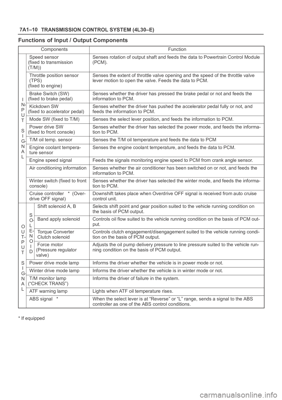
Functions of Input / Output Components
ComponentsFunction
Speed sensor
(fixed to transmission
(T/M))Senses rotation of output shaft and feeds the data to Powertrain Control Module
(PCM).
Throttle position sensor
(TPS)
(fixed to engine)Senses the extent of throttle valve opening and the speed of the throttle valve
lever motion to open the valve. Feeds the data to PCM.
I
N
Brake Switch (SW)
(fixed to brake pedal)Senses whether the driver has pressed the brake pedal or not and feeds the
information to PCM.
N-
P
U
Kickdown SW
(fixed to accelerator pedal)Senses whether the driver has pushed the accelerator pedal fully or not, and
feeds the information to PCM.
U
TMode SW (fixed to T/M)Senses the select lever position, and feeds the information to PCM.
S
I
Power drive SW
(fixed to front console)Senses whether the driver has selected the power mode, and feeds the informa-
tion to PCM.
I
G-T/M oil temp. sensorSenses the T/M oil temperature and feeds the data to PCM
N
A
L
Engine coolant tempera-
ture sensorSenses the engine coolant temperature, and feeds the data to PCM.
LEngine speed signalFeeds the signals monitoring engine speed to PCM from crank angle sensor.
Air conditioning informationSenses whether the air conditioner has been switched on or not, and feeds the
information to PCM.
Winter switch (fixed to front
console)Senses whether the driver has selected the winter mode, and feeds the informa-
tion to PCM.
Cruise controller * (Over-
drive OFF signal)Downshift takes place when Overdrive OFF signal is received from auto cruise
control unit.
S
Shift solenoid A, BSelects shift point and gear position suited to the vehicle running condition on
the basis of PCM output.
O
S
O-
L
Band apply solenoidControls oil flow suited to the vehicle running condition on the basis of PCM out-
put.
O
U
T-
P
E-
N
O
Torque Converter
Clutch solenoidControls clutch engagement/disengagement suited to the vehicle running condi-
tion on the basis of PCM output.
P
U
T
O
I
DForce motor
(Pressure regulator
valve)Adjusts the oil pump delivery pressure to line pressure suited to the vehicle run-
ning condition on the basis of PCM output.
S
I
Power drive mode lampInforms the driver whether the vehicle is in power mode or not.
I
G-Winter drive mode lampInforms the driver whether the vehicle is in winter mode or not.G
N
A
L
T/M monitor lamp
(“CHECK TRANS”)Informs the driver of failure in the system.
LATF warning lampLights when ATF oil temperature rises.
ABS signal *When the select lever is at “Reverse” or “L” range, sends a signal to the ABS
controller as one of the ABS control conditions.
* If equipped