1998 OPEL FRONTERA light
[x] Cancel search: lightPage 2267 of 6000
7A1–22
TRANSMISSION CONTROL SYSTEM (4L30–E)
connection or loose wiring. Terminals and grounds should
always be the prime suspect. Intermittents rarely occur
inside sophisticated electronic components such as the
PCM.
Use the DTC information to understand which wires and
sensors are involved.
When an intermittent problem is encountered, check
suspect circuits for:
1. Poor terminal to wire connection.
2. Terminals not fully seated in the connector body
(backed out).
3. Improperly formed or damaged terminals.
4. Loose, dirty, or corroded ground connections:
HINT: Any time you have an intermittent in more than
one circuit, check whether the circuits share a
common ground connection.
5. Pinched or damaged wires.
6. Electro–Magnetic Interference (EMI):
HINT: Check that all wires are properly routed away
from spark plug wires, distributor wires, coil, and
generator. Also check for improperly installed
electrical options, such as lights, 2–way radios, etc.Use the F3 SNAPSHOT mode of the Tech2 to help isolate
the cause of an intermittent fault. The snapshot mode will
record information before and after the problem occurs.
Set the snapshot to “trigger” on the suspect DTC. If you
notice the reported symptom during the test drive, trigger
the snapshot manually.
After the snapshot has been triggered, command the
Tech2 to play back the flow of data recorded from each of
the various sensors. Signs of an intermittent fault in a
sensor circuit are sudden unexplainable jump in data
values out of the normal range.
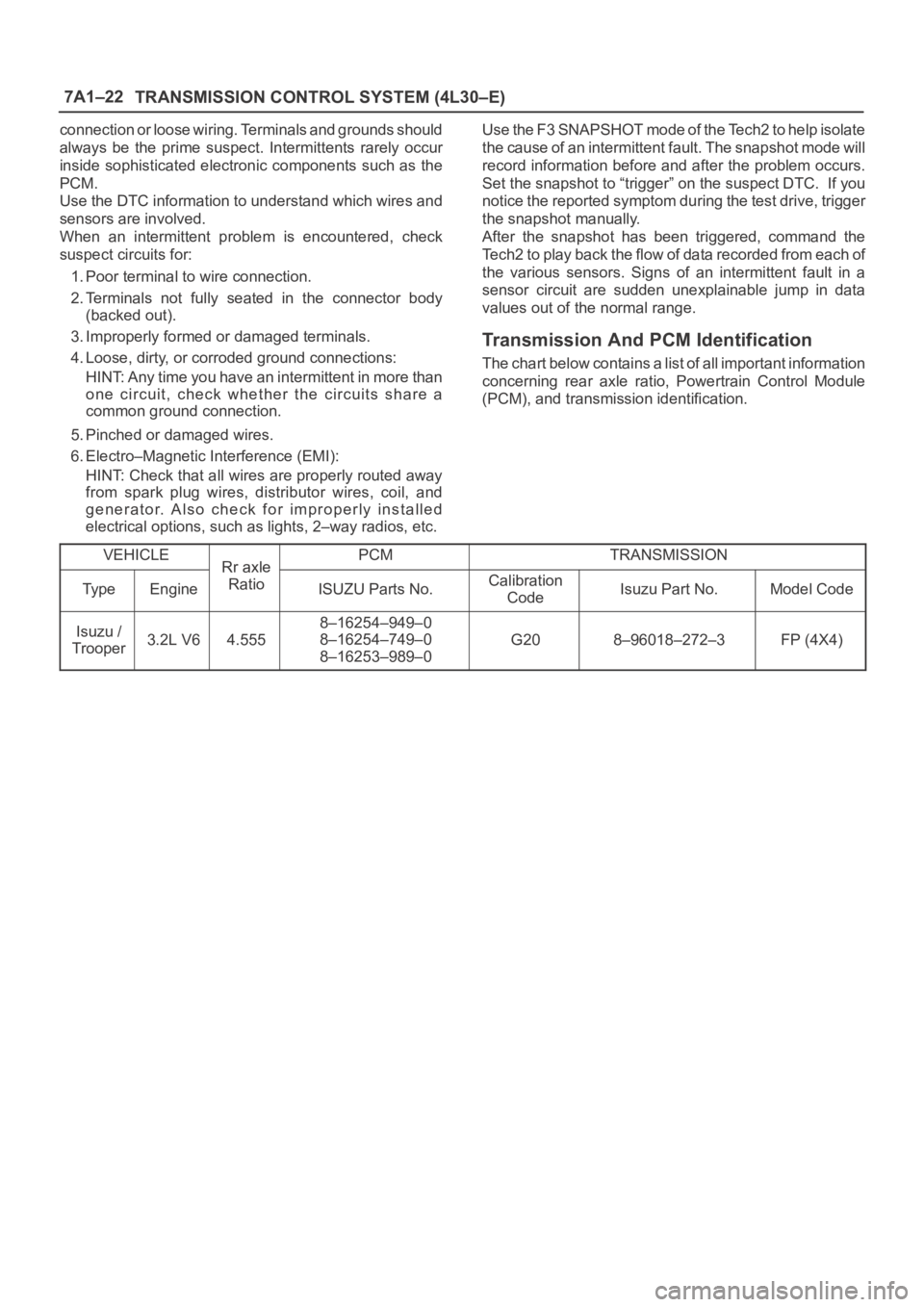
Transmission And PCM Identification
The chart below contains a list of all important information
concerning rear axle ratio, Powertrain Control Module
(PCM), and transmission identification.
VEHICLE
Rr axlePCMTRANSMISSION
Ty p eEngine
Rr axle
RatioISUZU Parts No.Calibration
CodeIsuzu Part No.Model Code
Isuzu /
Trooper3.2L V64.555
8–16254–949–0
8–16254–749–0
8–16253–989–0
G208–96018–272–3FP (4X4)
Page 2273 of 6000
7A1–28
TRANSMISSION CONTROL SYSTEM (4L30–E)
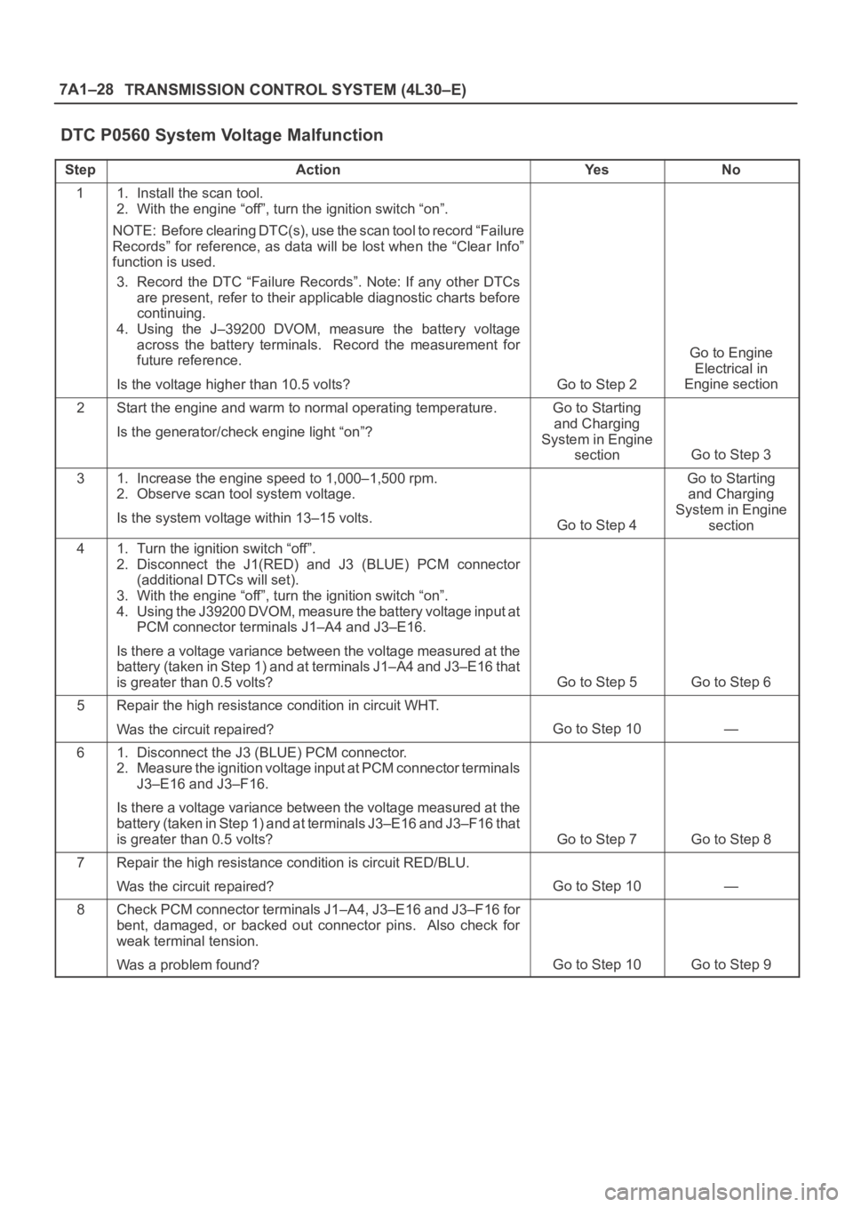
DTC P0560 System Voltage Malfunction
StepActionYe sNo
11. Install the scan tool.
2. With the engine “off”, turn the ignition switch “on”.
NOTE: Before clearing DTC(s), use the scan tool to record “Failure
Records” for reference, as data will be lost when the “Clear Info”
function is used.
3. Record the DTC “Failure Records”. Note: If any other DTCs
are present, refer to their applicable diagnostic charts before
continuing.
4. Using the J–39200 DVOM, measure the battery voltage
across the battery terminals. Record the measurement for
future reference.
Is the voltage higher than 10.5 volts?
Go to Step 2
Go to Engine
Electrical in
Engine section
2Start the engine and warm to normal operating temperature.
Is the generator/check engine light “on”?Go to Starting
and Charging
System in Engine
section
Go to Step 3
31. Increase the engine speed to 1,000–1,500 rpm.
2. Observe scan tool system voltage.
Is the system voltage within 13–15 volts.
Go to Step 4
Go to Starting
and Charging
System in Engine
section
41. Turn the ignition switch “off”.
2. Disconnect the J1(RED) and J3 (BLUE) PCM connector
(additional DTCs will set).
3. With the engine “off”, turn the ignition switch “on”.
4. Using the J39200 DVOM, measure the battery voltage input at
PCM connector terminals J1–A4 and J3–E16.
Is there a voltage variance between the voltage measured at the
battery (taken in Step 1) and at terminals J1–A4 and J3–E16 that
is greater than 0.5 volts?
Go to Step 5Go to Step 6
5Repair the high resistance condition in circuit WHT.
Was the circuit repaired?
Go to Step 10—
61. Disconnect the J3 (BLUE) PCM connector.
2. Measure the ignition voltage input at PCM connector terminals
J3–E16 and J3–F16.
Is there a voltage variance between the voltage measured at the
battery (taken in Step 1) and at terminals J3–E16 and J3–F16 that
is greater than 0.5 volts?
Go to Step 7Go to Step 8
7Repair the high resistance condition is circuit RED/BLU.
Was the circuit repaired?
Go to Step 10—
8Check PCM connector terminals J1–A4, J3–E16 and J3–F16 for
bent, damaged, or backed out connector pins. Also check for
weak terminal tension.
Was a problem found?
Go to Step 10Go to Step 9
Page 2288 of 6000
TRANSMISSION CONTROL SYSTEM (4L30–E)7A1–43
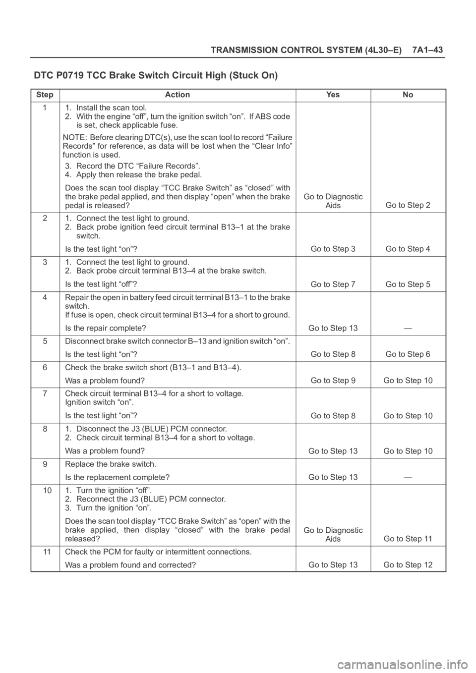
DTC P0719 TCC Brake Switch Circuit High (Stuck On)
StepActionYe sNo
11. Install the scan tool.
2. With the engine “off”, turn the ignition switch “on”. If ABS code
is set, check applicable fuse.
NOTE: Before clearing DTC(s), use the scan tool to record “Failure
Records” for reference, as data will be lost when the “Clear Info”
function is used.
3. Record the DTC “Failure Records”.
4. Apply then release the brake pedal.
Does the scan tool display “TCC Brake Switch” as “closed” with
the brake pedal applied, and then display “open” when the brake
pedal is released?
Go to Diagnostic
Aids
Go to Step 2
21. Connect the test light to ground.
2. Back probe ignition feed circuit terminal B13–1 at the brake
switch.
Is the test light “on”?
Go to Step 3Go to Step 4
31. Connect the test light to ground.
2. Back probe circuit terminal B13–4 at the brake switch.
Is the test light “off”?
Go to Step 7Go to Step 5
4Repair the open in battery feed circuit terminal B13–1 to the brake
switch.
If fuse is open, check circuit terminal B13–4 for a short to ground.
Is the repair complete?
Go to Step 13—
5Disconnect brake switch connector B–13 and ignition switch “on”.
Is the test light “on”?
Go to Step 8Go to Step 6
6Check the brake switch short (B13–1 and B13–4).
Was a problem found?
Go to Step 9Go to Step 10
7Check circuit terminal B13–4 for a short to voltage.
Ignition switch “on”.
Is the test light “on”?
Go to Step 8Go to Step 10
81. Disconnect the J3 (BLUE) PCM connector.
2. Check circuit terminal B13–4 for a short to voltage.
Was a problem found?
Go to Step 13Go to Step 10
9Replace the brake switch.
Is the replacement complete?
Go to Step 13—
101. Turn the ignition “off”.
2. Reconnect the J3 (BLUE) PCM connector.
3. Turn the ignition “on”.
Does the scan tool display “TCC Brake Switch” as “open” with the
brake applied, then display “closed” with the brake pedal
released?
Go to Diagnostic
Aids
Go to Step 11
11Check the PCM for faulty or intermittent connections.
Was a problem found and corrected?
Go to Step 13Go to Step 12
Page 2338 of 6000
7B–20MANUAL TRANSMISSION
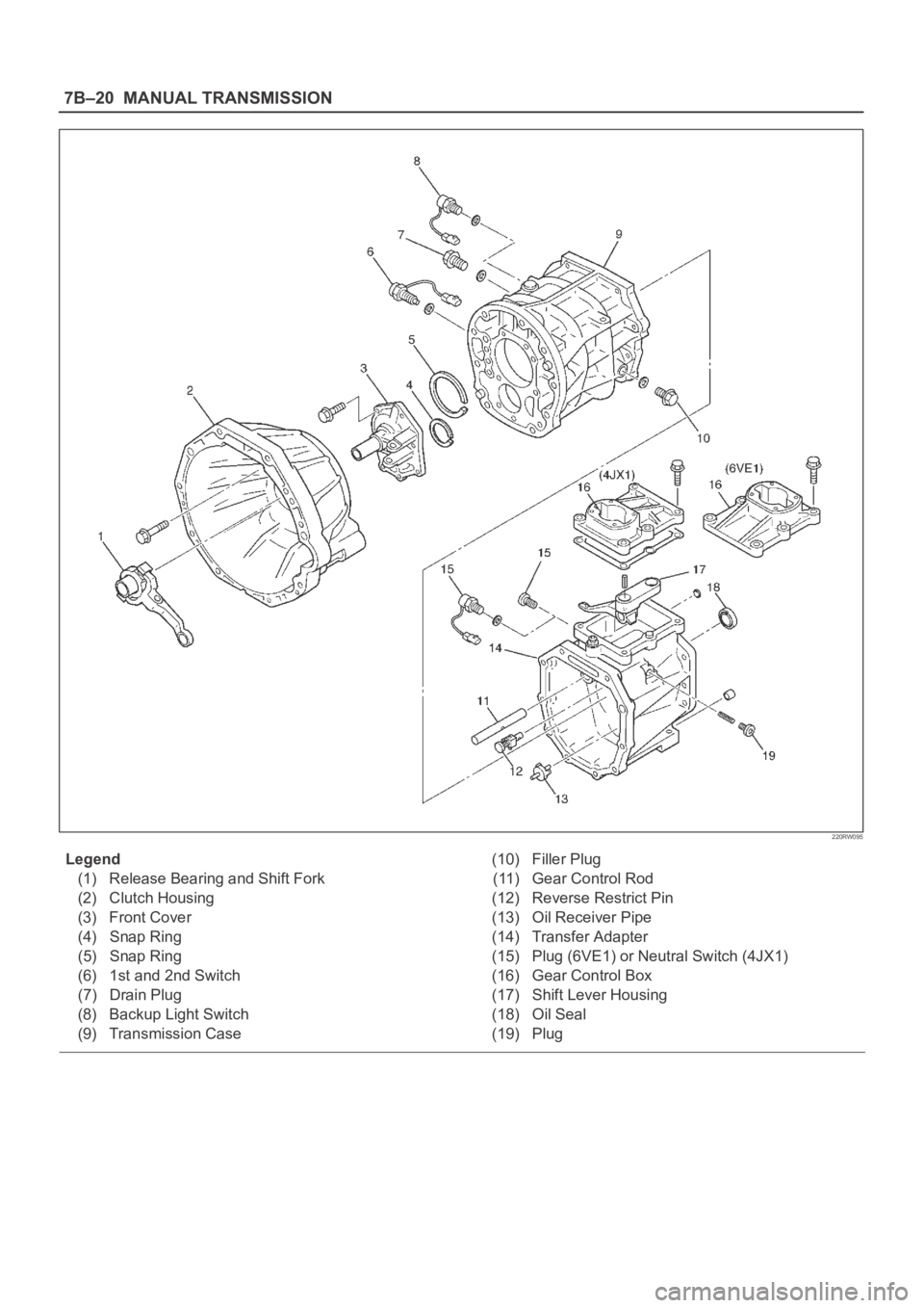
220RW095
Legend
(1) Release Bearing and Shift Fork
(2) Clutch Housing
(3) Front Cover
(4) Snap Ring
(5) Snap Ring
(6) 1st and 2nd Switch
(7) Drain Plug
(8) Backup Light Switch
(9) Transmission Case(10) Filler Plug
(11) Gear Control Rod
(12) Reverse Restrict Pin
(13) Oil Receiver Pipe
(14) Transfer Adapter
(15) Plug (6VE1) or Neutral Switch (4JX1)
(16) Gear Control Box
(17) Shift Lever Housing
(18) Oil Seal
(19) Plug
Page 2339 of 6000
MANUAL TRANSMISSION7B–21
Disassembly
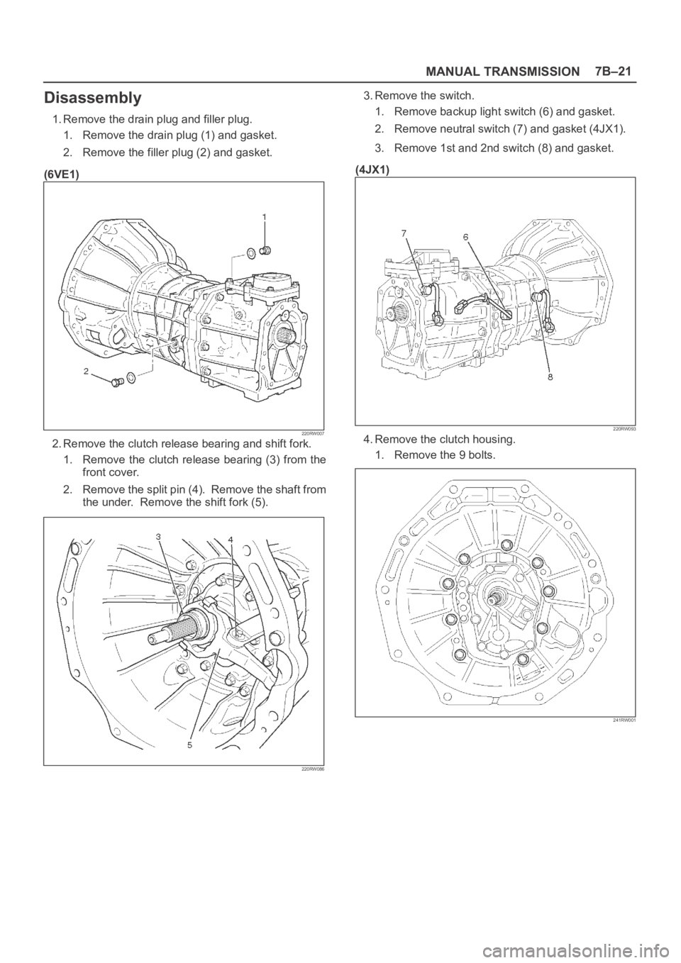
1. Remove the drain plug and filler plug.
1. Remove the drain plug (1) and gasket.
2. Remove the filler plug (2) and gasket.
(6VE1)
220RW007
2. Remove the clutch release bearing and shift fork.
1. Remove the clutch release bearing (3) from the
front cover.
2. Remove the split pin (4). Remove the shaft from
the under. Remove the shift fork (5).
220RW086
3. Remove the switch.
1. Remove backup light switch (6) and gasket.
2. Remove neutral switch (7) and gasket (4JX1).
3. Remove 1st and 2nd switch (8) and gasket.
(4JX1)
220RW093
4. Remove the clutch housing.
1. Remove the 9 bolts.
241RW001
Page 2384 of 6000
7B–66MANUAL TRANSMISSION
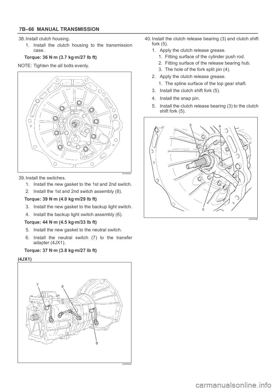
38. Install clutch housing.
1. Install the clutch housing to the transmission
case.
Torque: 36 Nꞏm (3.7 kgꞏm/27 lb ft)
NOTE: Tighten the all bolts evenly.
241RW001
39. Install the switches.
1. Install the new gasket to the 1st and 2nd switch.
2. Install the 1st and 2nd switch assembly (8).
Torque: 39 Nꞏm (4.0 kgꞏm/29 lb ft)
3. Install the new gasket to the backup light switch.
4. Install the backup light switch assembly (6).
Torque: 44 Nꞏm (4.5 kgꞏm/33 lb ft)
5. Install the new gasket to the neutral switch.
6. Install the neutral switch (7) to the transfer
adapter (4JX1).
Torque: 37 Nꞏm (3.8 kgꞏm/27 lb ft)
(4JX1)
220RW093
40. Install the clutch release bearing (3) and clutch shift
fork (5).
1. Apply the clutch release grease.
1. Fitting surface of the cylinder push rod.
2. Fitting surface of the release bearing hub.
3. The hole of the fork split pin (4).
2. Apply the clutch release grease.
1. The spline surface of the top gear shaft.
3. Install the clutch shift fork (5).
4. Install the snap pin.
5. Install the clutch release bearing (3) to the clutch
shift fork (5).
220RW086
Page 2540 of 6000
LIGHTING SYSTEM8A–1
BODY AND ACCESSORIES
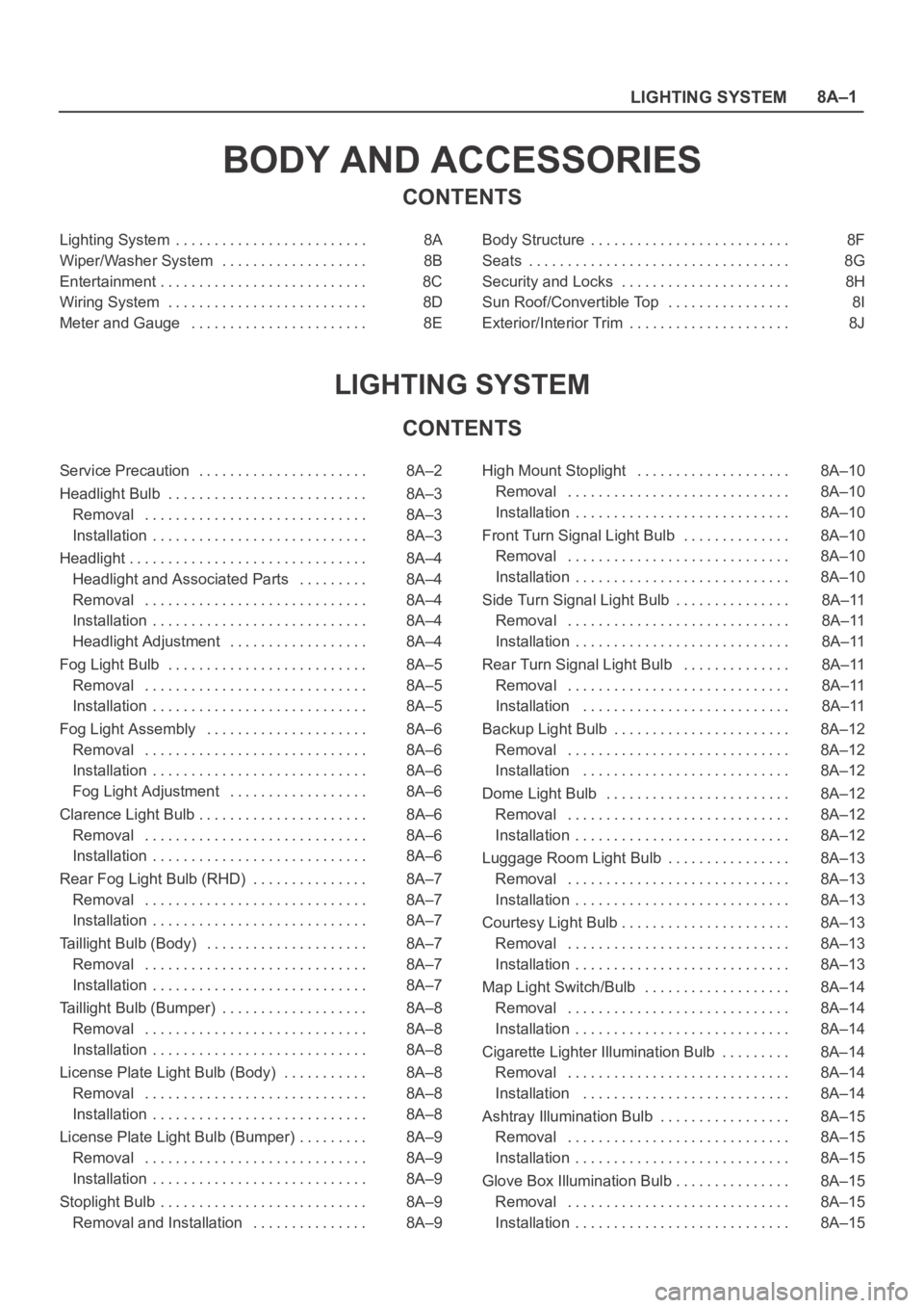
CONTENTS
Lighting System 8A. . . . . . . . . . . . . . . . . . . . . . . . .
Wiper/Washer System 8B. . . . . . . . . . . . . . . . . . .
Entertainment 8C. . . . . . . . . . . . . . . . . . . . . . . . . . .
Wiring System 8D. . . . . . . . . . . . . . . . . . . . . . . . . .
Meter and Gauge 8E. . . . . . . . . . . . . . . . . . . . . . . Body Structure 8F. . . . . . . . . . . . . . . . . . . . . . . . . .
Seats 8G. . . . . . . . . . . . . . . . . . . . . . . . . . . . . . . . . .
Security and Locks 8H. . . . . . . . . . . . . . . . . . . . . .
Sun Roof/Convertible Top 8I. . . . . . . . . . . . . . . .
Exterior/Interior Trim 8J. . . . . . . . . . . . . . . . . . . . .
LIGHTING SYSTEM
CONTENTS
Service Precaution 8A–2. . . . . . . . . . . . . . . . . . . . . .
Headlight Bulb 8A–3. . . . . . . . . . . . . . . . . . . . . . . . . .
Removal 8A–3. . . . . . . . . . . . . . . . . . . . . . . . . . . . .
Installation 8A–3. . . . . . . . . . . . . . . . . . . . . . . . . . . .
Headlight 8A–4. . . . . . . . . . . . . . . . . . . . . . . . . . . . . . .
Headlight and Associated Parts 8A–4. . . . . . . . .
Removal 8A–4. . . . . . . . . . . . . . . . . . . . . . . . . . . . .
Installation 8A–4. . . . . . . . . . . . . . . . . . . . . . . . . . . .
Headlight Adjustment 8A–4. . . . . . . . . . . . . . . . . .
Fog Light Bulb 8A–5. . . . . . . . . . . . . . . . . . . . . . . . . .
Removal 8A–5. . . . . . . . . . . . . . . . . . . . . . . . . . . . .
Installation 8A–5. . . . . . . . . . . . . . . . . . . . . . . . . . . .
Fog Light Assembly 8A–6. . . . . . . . . . . . . . . . . . . . .
Removal 8A–6. . . . . . . . . . . . . . . . . . . . . . . . . . . . .
Installation 8A–6. . . . . . . . . . . . . . . . . . . . . . . . . . . .
Fog Light Adjustment 8A–6. . . . . . . . . . . . . . . . . .
Clarence Light Bulb 8A–6. . . . . . . . . . . . . . . . . . . . . .
Removal 8A–6. . . . . . . . . . . . . . . . . . . . . . . . . . . . .
Installation 8A–6. . . . . . . . . . . . . . . . . . . . . . . . . . . .
Rear Fog Light Bulb (RHD) 8A–7. . . . . . . . . . . . . . .
Removal 8A–7. . . . . . . . . . . . . . . . . . . . . . . . . . . . .
Installation 8A–7. . . . . . . . . . . . . . . . . . . . . . . . . . . .
Taillight Bulb (Body) 8A–7. . . . . . . . . . . . . . . . . . . . .
Removal 8A–7. . . . . . . . . . . . . . . . . . . . . . . . . . . . .
Installation 8A–7. . . . . . . . . . . . . . . . . . . . . . . . . . . .
Taillight Bulb (Bumper) 8A–8. . . . . . . . . . . . . . . . . . .
Removal 8A–8. . . . . . . . . . . . . . . . . . . . . . . . . . . . .
Installation 8A–8. . . . . . . . . . . . . . . . . . . . . . . . . . . .
License Plate Light Bulb (Body) 8A–8. . . . . . . . . . .
Removal 8A–8. . . . . . . . . . . . . . . . . . . . . . . . . . . . .
Installation 8A–8. . . . . . . . . . . . . . . . . . . . . . . . . . . .
License Plate Light Bulb (Bumper) 8A–9. . . . . . . . .
Removal 8A–9. . . . . . . . . . . . . . . . . . . . . . . . . . . . .
Installation 8A–9. . . . . . . . . . . . . . . . . . . . . . . . . . . .
Stoplight Bulb 8A–9. . . . . . . . . . . . . . . . . . . . . . . . . . .
Removal and Installation 8A–9. . . . . . . . . . . . . . . High Mount Stoplight 8A–10. . . . . . . . . . . . . . . . . . . .
Removal 8A–10. . . . . . . . . . . . . . . . . . . . . . . . . . . . .
Installation 8A–10. . . . . . . . . . . . . . . . . . . . . . . . . . . .
Front Turn Signal Light Bulb 8A–10. . . . . . . . . . . . . .
Removal 8A–10. . . . . . . . . . . . . . . . . . . . . . . . . . . . .
Installation 8A–10. . . . . . . . . . . . . . . . . . . . . . . . . . . .
Side Turn Signal Light Bulb 8A–11. . . . . . . . . . . . . . .
Removal 8A–11. . . . . . . . . . . . . . . . . . . . . . . . . . . . .
Installation 8A–11. . . . . . . . . . . . . . . . . . . . . . . . . . . .
Rear Turn Signal Light Bulb 8A–11. . . . . . . . . . . . . .
Removal 8A–11. . . . . . . . . . . . . . . . . . . . . . . . . . . . .
Installation 8A–11. . . . . . . . . . . . . . . . . . . . . . . . . . .
Backup Light Bulb 8A–12. . . . . . . . . . . . . . . . . . . . . . .
Removal 8A–12. . . . . . . . . . . . . . . . . . . . . . . . . . . . .
Installation 8A–12
. . . . . . . . . . . . . . . . . . . . . . . . . . .
Dome Light Bulb 8A–12. . . . . . . . . . . . . . . . . . . . . . . .
Removal 8A–12. . . . . . . . . . . . . . . . . . . . . . . . . . . . .
Installation 8A–12. . . . . . . . . . . . . . . . . . . . . . . . . . . .
Luggage Room Light Bulb 8A–13. . . . . . . . . . . . . . . .
Removal 8A–13. . . . . . . . . . . . . . . . . . . . . . . . . . . . .
Installation 8A–13. . . . . . . . . . . . . . . . . . . . . . . . . . . .
Courtesy Light Bulb 8A–13. . . . . . . . . . . . . . . . . . . . . .
Removal 8A–13. . . . . . . . . . . . . . . . . . . . . . . . . . . . .
Installation 8A–13. . . . . . . . . . . . . . . . . . . . . . . . . . . .
Map Light Switch/Bulb 8A–14. . . . . . . . . . . . . . . . . . .
Removal 8A–14. . . . . . . . . . . . . . . . . . . . . . . . . . . . .
Installation 8A–14. . . . . . . . . . . . . . . . . . . . . . . . . . . .
Cigarette Lighter Illumination Bulb 8A–14. . . . . . . . .
Removal 8A–14. . . . . . . . . . . . . . . . . . . . . . . . . . . . .
Installation 8A–14. . . . . . . . . . . . . . . . . . . . . . . . . . .
Ashtray Illumination Bulb 8A–15. . . . . . . . . . . . . . . . .
Removal 8A–15. . . . . . . . . . . . . . . . . . . . . . . . . . . . .
Installation 8A–15. . . . . . . . . . . . . . . . . . . . . . . . . . . .
Glove Box Illumination Bulb 8A–15. . . . . . . . . . . . . . .
Removal 8A–15. . . . . . . . . . . . . . . . . . . . . . . . . . . . .
Installation 8A–15. . . . . . . . . . . . . . . . . . . . . . . . . . . .
Page 2541 of 6000
8A–2LIGHTING SYSTEM
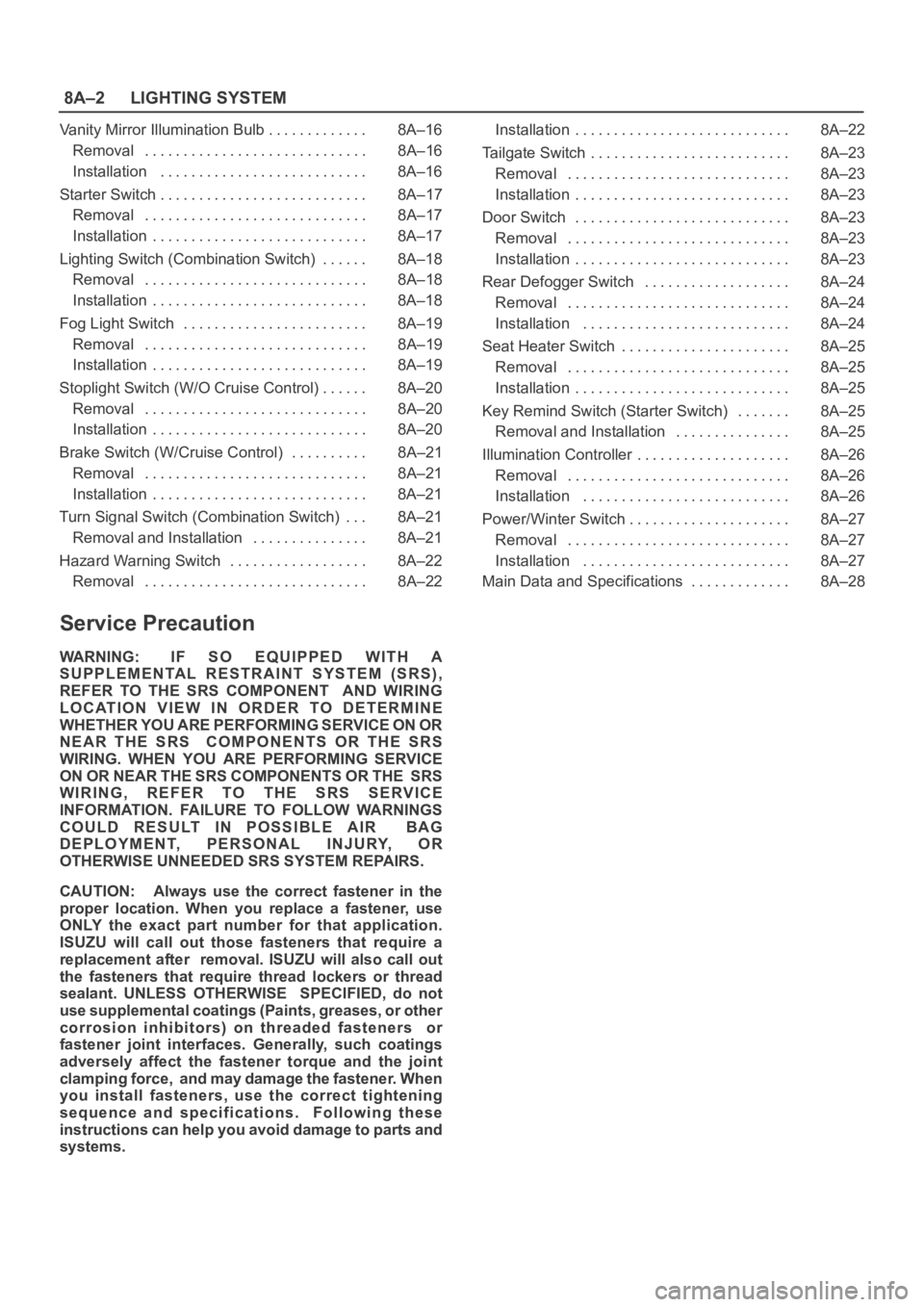
Vanity Mirror Illumination Bulb 8A–16. . . . . . . . . . . . .
Removal 8A–16. . . . . . . . . . . . . . . . . . . . . . . . . . . . .
Installation 8A–16. . . . . . . . . . . . . . . . . . . . . . . . . . .
Starter Switch 8A–17. . . . . . . . . . . . . . . . . . . . . . . . . . .
Removal 8A–17. . . . . . . . . . . . . . . . . . . . . . . . . . . . .
Installation 8A–17. . . . . . . . . . . . . . . . . . . . . . . . . . . .
Lighting Switch (Combination Switch) 8A–18. . . . . .
Removal 8A–18. . . . . . . . . . . . . . . . . . . . . . . . . . . . .
Installation 8A–18. . . . . . . . . . . . . . . . . . . . . . . . . . . .
Fog Light Switch 8A–19. . . . . . . . . . . . . . . . . . . . . . . .
Removal 8A–19. . . . . . . . . . . . . . . . . . . . . . . . . . . . .
Installation 8A–19. . . . . . . . . . . . . . . . . . . . . . . . . . . .
Stoplight Switch (W/O Cruise Control) 8A–20. . . . . .
Removal 8A–20. . . . . . . . . . . . . . . . . . . . . . . . . . . . .
Installation 8A–20. . . . . . . . . . . . . . . . . . . . . . . . . . . .
Brake Switch (W/Cruise Control) 8A–21. . . . . . . . . .
Removal 8A–21. . . . . . . . . . . . . . . . . . . . . . . . . . . . .
Installation 8A–21. . . . . . . . . . . . . . . . . . . . . . . . . . . .
Turn Signal Switch (Combination Switch) 8A–21. . .
Removal and Installation 8A–21. . . . . . . . . . . . . . .
Hazard Warning Switch 8A–22. . . . . . . . . . . . . . . . . .
Removal 8A–22. . . . . . . . . . . . . . . . . . . . . . . . . . . . . Installation 8A–22. . . . . . . . . . . . . . . . . . . . . . . . . . . .
Tailgate Switch 8A–23. . . . . . . . . . . . . . . . . . . . . . . . . .
Removal 8A–23. . . . . . . . . . . . . . . . . . . . . . . . . . . . .
Installation 8A–23. . . . . . . . . . . . . . . . . . . . . . . . . . . .
Door Switch 8A–23. . . . . . . . . . . . . . . . . . . . . . . . . . . .
Removal 8A–23. . . . . . . . . . . . . . . . . . . . . . . . . . . . .
Installation 8A–23. . . . . . . . . . . . . . . . . . . . . . . . . . . .
Rear Defogger Switch 8A–24. . . . . . . . . . . . . . . . . . .
Removal 8A–24. . . . . . . . . . . . . . . . . . . . . . . . . . . . .
Installation 8A–24. . . . . . . . . . . . . . . . . . . . . . . . . . .
Seat Heater Switch 8A–25. . . . . . . . . . . . . . . . . . . . . .
Removal 8A–25. . . . . . . . . . . . . . . . . . . . . . . . . . . . .
Installation 8A–25. . . . . . . . . . . . . . . . . . . . . . . . . . . .
Key Remind Switch (Starter Switch) 8A–25. . . . . . .
Removal and Installation 8A–25. . . . . . . . . . . . . . .
Illumination Controller 8A–26. . . . . . . . . . . . . . . . . . . .
Removal 8A–26. . . . . . . . . . . . . . . . . . . . . . . . . . . . .
Installation 8A–26. . . . . . . . . . . . . . . . . . . . . . . . . . .
Power/Winter Switch 8A–27. . . . . . . . . . . . . . . . . . . . .
Removal 8A–27. . . . . . . . . . . . . . . . . . . . . . . . . . . . .
Installation 8A–27. . . . . . . . . . . . . . . . . . . . . . . . . . .
Main Data and Specifications 8A–28. . . . . . . . . . . . .
Service Precaution
WARNING: IF SO EQUIPPED WITH A
SUPPLEMENTAL RESTRAINT SYSTEM (SRS),
REFER TO THE SRS COMPONENT AND WIRING
LOCATION VIEW IN ORDER TO DETERMINE
WHETHER YOU ARE PERFORMING SERVICE ON OR
NEAR THE SRS COMPONENTS OR THE SRS
WIRING. WHEN YOU ARE PERFORMING SERVICE
ON OR NEAR THE SRS COMPONENTS OR THE SRS
WIRING, REFER TO THE SRS SERVICE
INFORMATION. FAILURE TO FOLLOW WARNINGS
COULD RESULT IN POSSIBLE AIR BAG
DEPLOYMENT, PERSONAL INJURY, OR
OTHERWISE UNNEEDED SRS SYSTEM REPAIRS.
CAUTION: Always use the correct fastener in the
proper location. When you replace a fastener, use
ONLY the exact part number for that application.
ISUZU will call out those fasteners that require a
replacement after removal. ISUZU will also call out
the fasteners that require thread lockers or thread
sealant. UNLESS OTHERWISE SPECIFIED, do not
use supplemental coatings (Paints, greases, or other
corrosion inhibitors) on threaded fasteners or
fastener joint interfaces. Generally, such coatings
adversely affect the fastener torque and the joint
clamping force, and may damage the fastener. When
you install fasteners, use the correct tightening
sequence and specifications. Following these
instructions can help you avoid damage to parts and
systems.