1998 OPEL FRONTERA cooling
[x] Cancel search: coolingPage 5299 of 6000
6A – 26 ENGINE MECHANICAL
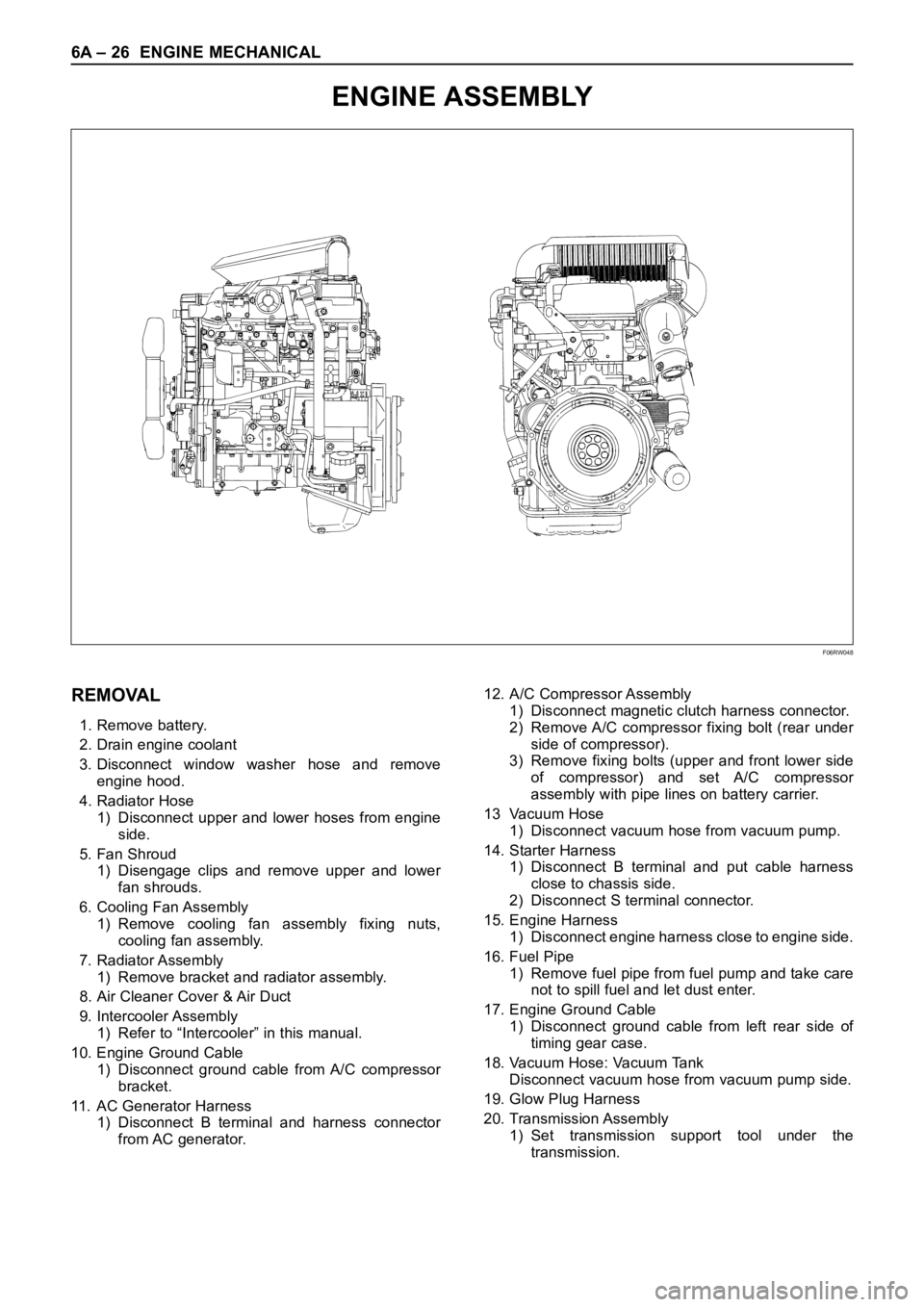
ENGINE ASSEMBLY
F06RW048
REMOVAL
1. Remove battery.
2. Drain engine coolant
3. Disconnect window washer hose and remove
engine hood.
4. Radiator Hose
1) Disconnect upper and lower hoses from engine
side.
5. Fan Shroud
1) Disengage clips and remove upper and lower
fan shrouds.
6. Cooling Fan Assembly
1) Remove cooling fan assembly fixing nuts,
cooling fan assembly.
7. Radiator Assembly
1) Remove bracket and radiator assembly.
8. Air Cleaner Cover & Air Duct
9. Intercooler Assembly
1) Refer to “Intercooler” in this manual.
10. Engine Ground Cable
1) Disconnect ground cable from A/C compressor
bracket.
11. AC Generator Harness
1) Disconnect B terminal and harness connector
from AC generator.12. A/C Compressor Assembly
1) Disconnect magnetic clutch harness connector.
2) Remove A/C compressor fixing bolt (rear under
side of compressor).
3) Remove fixing bolts (upper and front lower side
of compressor) and set A/C compressor
assembly with pipe lines on battery carrier.
13 Vacuum Hose
1) Disconnect vacuum hose from vacuum pump.
14. Starter Harness
1) Disconnect B terminal and put cable harness
close to chassis side.
2) Disconnect S terminal connector.
15. Engine Harness
1) Disconnect engine harness close to engine side.
16. Fuel Pipe
1) Remove fuel pipe from fuel pump and take care
not to spill fuel and let dust enter.
17. Engine Ground Cable
1) Disconnect ground cable from left rear side of
timing gear case.
18. Vacuum Hose: Vacuum Tank
Disconnect vacuum hose from vacuum pump side.
19. Glow Plug Harness
20. Transmission Assembly
1) Set transmission support tool under the
transmission.
Page 5300 of 6000

ENGINE MECHANICAL 6A – 27
2) Remove transmission rear mount.
3) Remove transmission fixing bolt from rear of
engine assembly except two bolts.
4) Carefully hang up engine assembly with a hoist.
5) Remove remaining two transmission fixing bolts.
6) Remove transmission assembly.
7) Remove heater hose.
8) Disconnect wire harness connector for shift on
the fly.
9) Remove vacuum hose.
21. Prepare Engine Stand
22. Engine Assembly
1) Remove engine mount fixing bolts.
2) Carefully hang up the engine assembly.
3) Take out the engine assembly making sure not
to damage the brake oil pipe and other pipe etc.
INSTALLATION
1. Engine assembly
1) Install engine in mounting position by using
hoist.
2. Transmission Assembly
1) Refer to transmission installation steps in
section 7.
3. Engine Mounting
1) After all fixing bolts (left: two bolts, rights: two
bolts) were inserted in every hole, tighten fixing
bolts to the specified torque.
Torque: 40 Nꞏm (4 kgꞏm/29 lbꞏft)
4. Glow Plug Harness
5. Vacuum Hose
1) Connect Vacuum Hose to Vacuum Pump
6. Engine Ground Cable
7. Fuel Pipe
1) Install fuel pipe to fuel pump.
8. Engine Harness
9. Starter Harness
10. A/C Compressor Assembly
1) Tighten temporarily the fixing bolts (upper and
front lower sides of compressor.)
2) Tighten fixing bolt (rear under side of
compressor) to the specified torque.
3) Tighten fixing bolts (front upper and lower sides
of compressor) to the specified torque.
Torque: 40 Nꞏm (4 kgꞏm/29 lbꞏft)Legend
(1) Tensioner
(2) Bolt
(3) Bracket
(4) A/C compressor
(5) Bolt
11. A.C Generator Harness
12. Engine Ground Cable
1) Tighten ground cable to A/C compressor
bracket.
13. Air Cleaner cover & Duct
14. Intercooler Assembly
1) Refer to “Intercooler” in this manual.
15. Radiator Assembly
1) Install rubber cushion in under left and right part
of radiator and position radiator.
2) Fix radiator with bracket.
16. Cooling Fan Assembly
1) Install cooling fan assembly and tighten fixing
bolts to the specified torque.
Torque: 8 Nꞏm (0.8 kgꞏm/5.8 lb ft)
17. Fan Shroud
18. Radiator Hose
1) Connect upper and lower hose to engine side.
2) Pour coolant into radiator.
19. Install battery.
20. Connect window washer hose and install engine
hood.
1
2
3
4
5
F06RW054
Page 5321 of 6000
6A – 48 ENGINE MECHANICAL
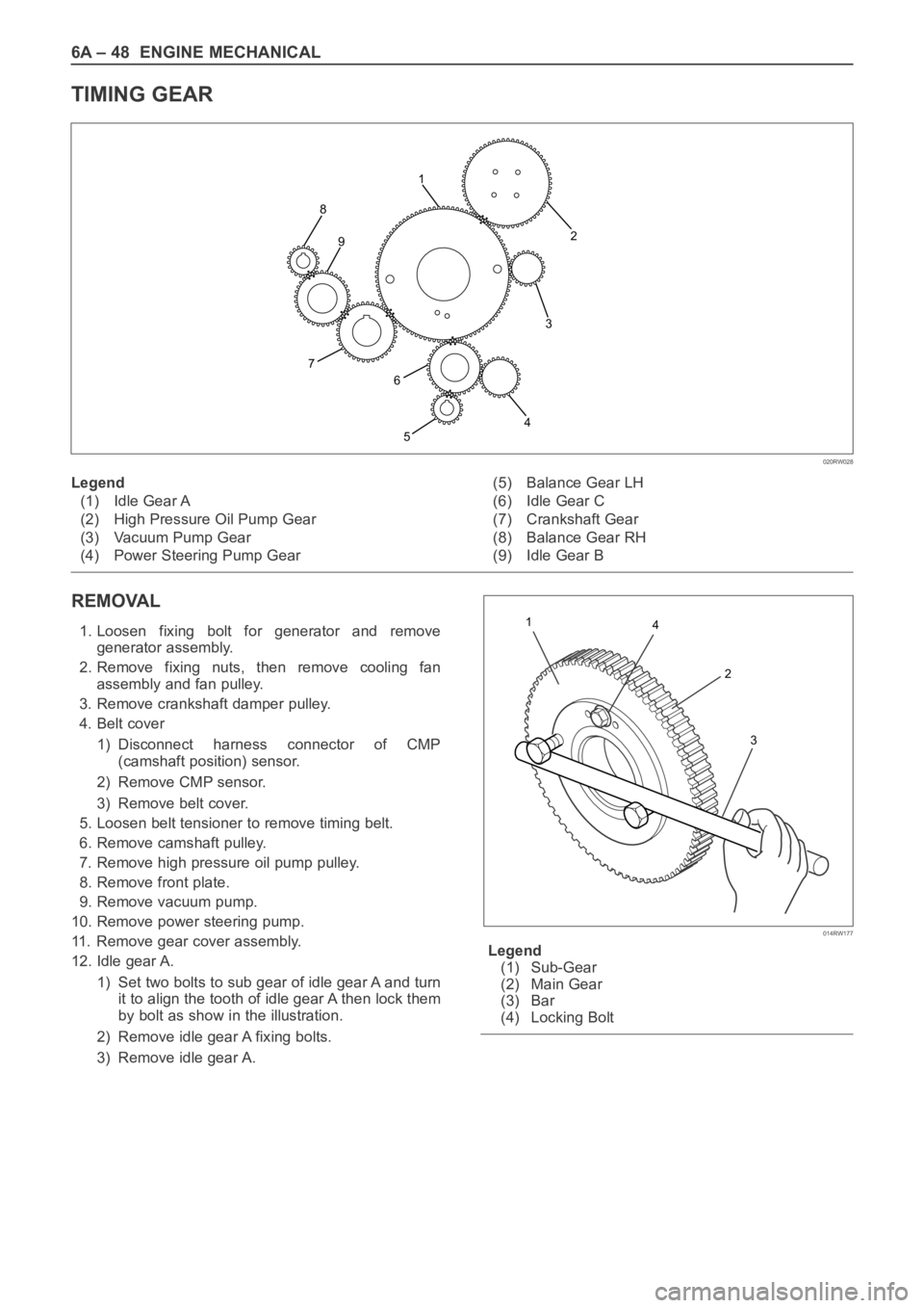
TIMING GEAR
REMOVAL
1. Loosen fixing bolt for generator and remove
generator assembly.
2. Remove fixing nuts, then remove cooling fan
assembly and fan pulley.
3. Remove crankshaft damper pulley.
4. Belt cover
1) Disconnect harness connector of CMP
(camshaft position) sensor.
2) Remove CMP sensor.
3) Remove belt cover.
5. Loosen belt tensioner to remove timing belt.
6. Remove camshaft pulley.
7. Remove high pressure oil pump pulley.
8. Remove front plate.
9. Remove vacuum pump.
10. Remove power steering pump.
11. Remove gear cover assembly.
12. Idle gear A.
1) Set two bolts to sub gear of idle gear A and turn
it to align the tooth of idle gear A then lock them
by bolt as show in the illustration.
2) Remove idle gear A fixing bolts.
3) Remove idle gear A.Legend
(1) Sub-Gear
(2) Main Gear
(3) Bar
(4) Locking Bolt
2
3
4
5 8
7
6 91
020RW028
Legend
(1) Idle Gear A
(2) High Pressure Oil Pump Gear
(3) Vacuum Pump Gear
(4) Power Steering Pump Gear(5) Balance Gear LH
(6) Idle Gear C
(7) Crankshaft Gear
(8) Balance Gear RH
(9) Idle Gear B
4 1
2
3
014RW177
Page 5328 of 6000
ENGINE MECHANICAL 6A – 55
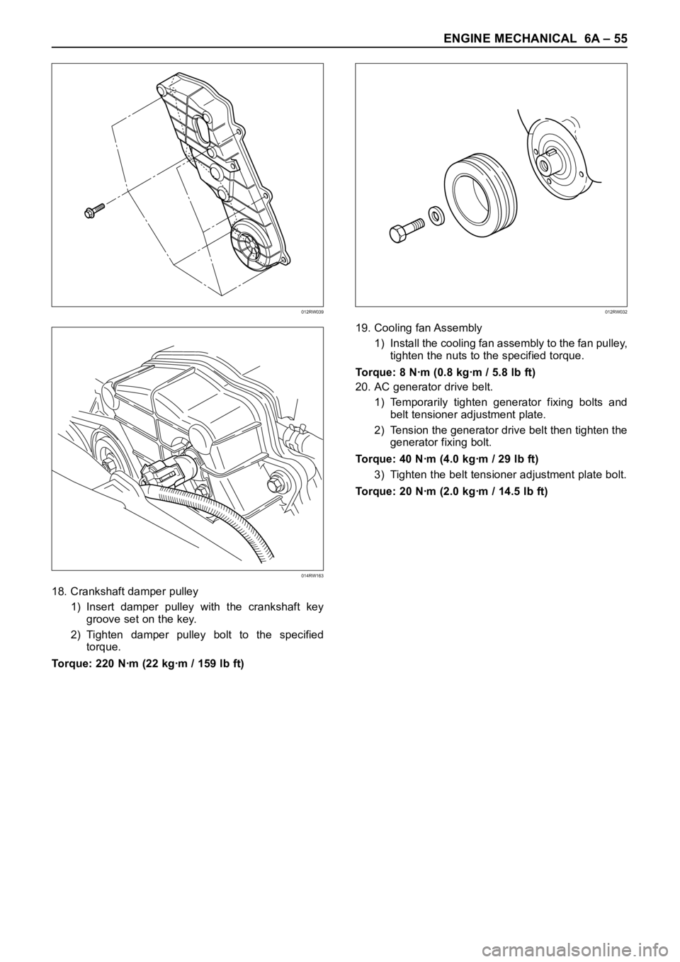
18. Crankshaft damper pulley
1) Insert damper pulley with the crankshaft key
groove set on the key.
2) Tighten damper pulley bolt to the specified
torque.
Torque: 220 Nꞏm (22 kgꞏm / 159 lb ft)19. Cooling fan Assembly
1) Install the cooling fan assembly to the fan pulley,
tighten the nuts to the specified torque.
Torque: 8 Nꞏm (0.8 kgꞏm / 5.8 lb ft)
20. AC generator drive belt.
1) Temporarily tighten generator fixing bolts and
belt tensioner adjustment plate.
2) Tension the generator drive belt then tighten the
generator fixing bolt.
Torque: 40 Nꞏm (4.0 kgꞏm / 29 lb ft)
3) Tighten the belt tensioner adjustment plate bolt.
Torque: 20 Nꞏm (2.0 kgꞏm / 14.5 lb ft)
012RW039
014RW163
012RW032
Page 5329 of 6000
6A – 56 ENGINE MECHANICAL
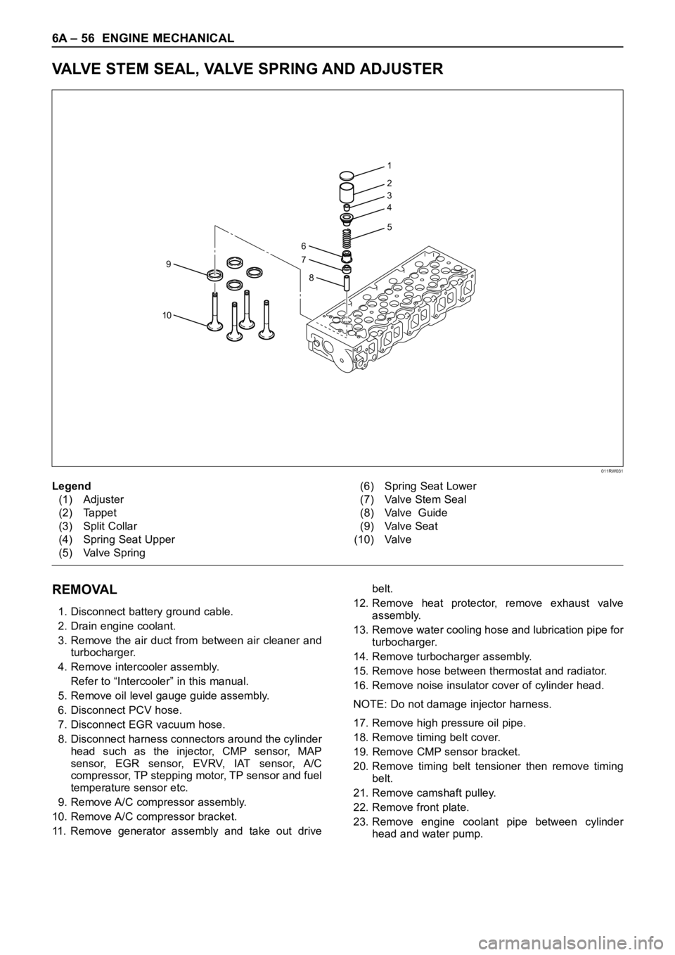
VALVE STEM SEAL, VALVE SPRING AND ADJUSTER
REMOVAL
1. Disconnect battery ground cable.
2. Drain engine coolant.
3. Remove the air duct from between air cleaner and
turbocharger.
4. Remove intercooler assembly.
Refer to “Intercooler” in this manual.
5. Remove oil level gauge guide assembly.
6. Disconnect PCV hose.
7. Disconnect EGR vacuum hose.
8. Disconnect harness connectors around the cylinder
head such as the injector, CMP sensor, MAP
sensor, EGR sensor, EVRV, IAT sensor, A/C
compressor, TP stepping motor, TP sensor and fuel
temperature sensor etc.
9. Remove A/C compressor assembly.
10. Remove A/C compressor bracket.
11. Remove generator assembly and take out drivebelt.
12. Remove heat protector, remove exhaust valve
assembly.
13. Remove water cooling hose and lubrication pipe for
turbocharger.
14. Remove turbocharger assembly.
15. Remove hose between thermostat and radiator.
16. Remove noise insulator cover of cylinder head.
NOTE: Do not damage injector harness.
17. Remove high pressure oil pipe.
18. Remove timing belt cover.
19. Remove CMP sensor bracket.
20. Remove timing belt tensioner then remove timing
belt.
21. Remove camshaft pulley.
22. Remove front plate.
23. Remove engine coolant pipe between cylinder
head and water pump.
1
2
3
4
5
6
9
10
7
8
011RW031
Legend
(1) Adjuster
(2) Tappet
(3) Split Collar
(4) Spring Seat Upper
(5) Valve Spring(6) Spring Seat Lower
(7) Valve Stem Seal
(8) Valve Guide
(9) Valve Seat
(10) Valve
Page 5343 of 6000
6A – 70 ENGINE MECHANICAL
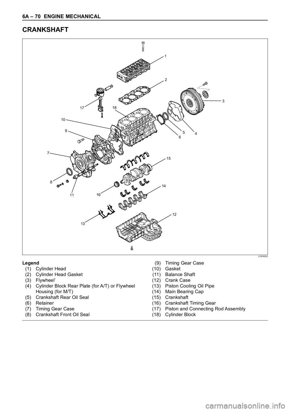
CRANKSHAFT
1
15
14
13
8
11
16
17
10
9
72
12
3
465
18
012RW023
Legend
(1) Cylinder Head
(2) Cylinder Head Gasket
(3) Flywheel’
(4) Cylinder Block Rear Plate (for A/T) or Flywheel
Housing (for M/T)
(5) Crankshaft Rear Oil Seal
(6) Retainer
(7) Timing Gear Case
(8) Crankshaft Front Oil Seal(9) Timing Gear Case
(10) Gasket
(11) Balance Shaft
(12) Crank Case
(13) Piston Cooling Oil Pipe
(14) Main Bearing Cap
(15) Crankshaft
(16) Crankshaft Timing Gear
(17) Piston and Connecting Rod Assembly
(18) Cylinder Block
Page 5344 of 6000
ENGINE MECHANICAL 6A – 71
DISASSEMBLY
1. Cylinder Head
1) Refer to “Cylinder head” in this manual.
2. Crankshaft Front Oil Seal
1) Use a plastic hammer and a screwdriver to tap
around the oil seal to free it from the gear case
cover.
Take care not to damage the oil seal fitting
surfaces.
3. Crankshaft Timing Gear
4. Timing Gear Case
5. Flywheel
6. Cylinder Block Rear Plate
7. Crankshaft Rear Oil Seal
1) Use special tool to remove the crankshaft rear
oil seal.
Oil Seal Remover: 5-8840-2360-0
8. Crank Case
9. Piston Cooling Oil Pipe
10. Piston and Connecting Rod Assembly
11. Main Bearing Cap Assembly
12. Crankshaft
INSPECTION AND REPAIR
Make the necessary adjustments, repairs, and part
replacements if excessive wear or damage is
discovered during inspection.
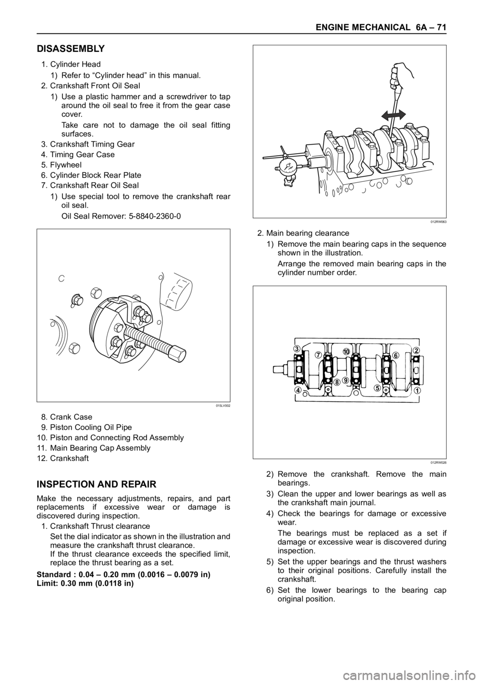
1. Crankshaft Thrust clearance
Set the dial indicator as shown in the illustration and
measure the crankshaft thrust clearance.
If the thrust clearance exceeds the specified limit,
replace the thrust bearing as a set.
Standard : 0.04 – 0.20 mm (0.0016 – 0.0079 in)
Limit: 0.30 mm (0.0118 in)2. Main bearing clearance
1) Remove the main bearing caps in the sequence
shown in the illustration.
Arrange the removed main bearing caps in the
cylinder number order.
2) Remove the crankshaft. Remove the main
bearings.
3) Clean the upper and lower bearings as well as
the crankshaft main journal.
4) Check the bearings for damage or excessive
wear.
The bearings must be replaced as a set if
damage or excessive wear is discovered during
inspection.
5) Set the upper bearings and the thrust washers
to their original positions. Carefully install the
crankshaft.
6) Set the lower bearings to the bearing cap
original position.
015LV002
012RW063
371062
51
984
012RW026
Page 5349 of 6000
6A – 76 ENGINE MECHANICAL
3. Piston and Connecting Rod Assembly
1) Apply engine oil to the cylinder bores, the
connecting rod bearings and the crankshaft pins
and each piston ring and piston.
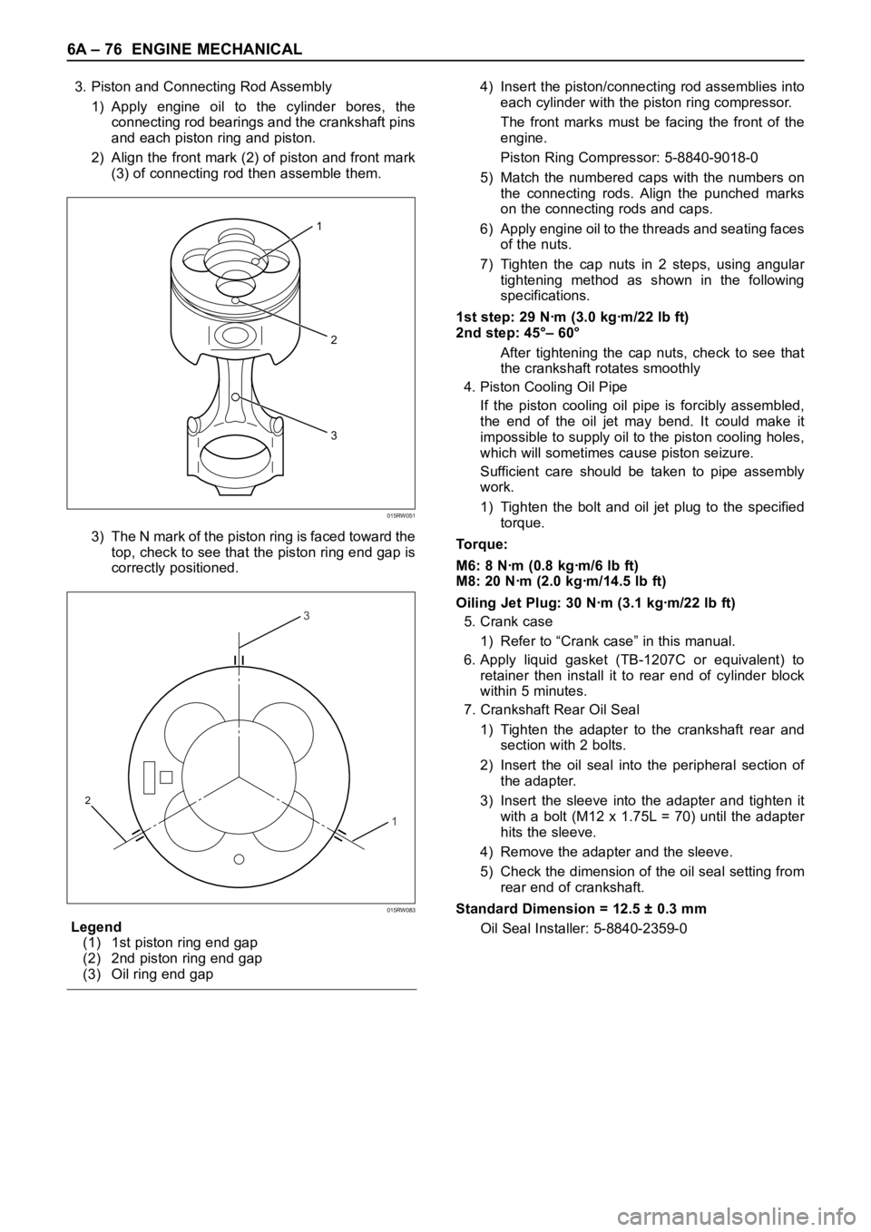
2) Align the front mark (2) of piston and front mark
(3) of connecting rod then assemble them.
3) The N mark of the piston ring is faced toward the
top, check to see that the piston ring end gap is
correctly positioned.
Legend
(1) 1st piston ring end gap
(2) 2nd piston ring end gap
(3) Oil ring end gap4) Insert the piston/connecting rod assemblies into
each cylinder with the piston ring compressor.
The front marks must be facing the front of the
engine.
Piston Ring Compressor: 5-8840-9018-0
5) Match the numbered caps with the numbers on
the connecting rods. Align the punched marks
on the connecting rods and caps.
6) Apply engine oil to the threads and seating faces
of the nuts.
7) Tighten the cap nuts in 2 steps, using angular
tightening method as shown in the following
specifications.
1st step: 29 Nꞏm (3.0 kgꞏm/22 lb ft)
2nd step: 45°– 60°
After tightening the cap nuts, check to see that
the crankshaft rotates smoothly
4. Piston Cooling Oil Pipe
If the piston cooling oil pipe is forcibly assembled,
the end of the oil jet may bend. It could make it
impossible to supply oil to the piston cooling holes,
which will sometimes cause piston seizure.
Sufficient care should be taken to pipe assembly
work.
1) Tighten the bolt and oil jet plug to the specified
torque.
To r q u e :
M6: 8 Nꞏm (0.8 kgꞏm/6 lb ft)
M8: 20 Nꞏm (2.0 kgꞏm/14.5 lb ft)
Oiling Jet Plug: 30 Nꞏm (3.1 kgꞏm/22 lb ft)
5. Crank case
1) Refer to “Crank case” in this manual.
6. Apply liquid gasket (TB-1207C or equivalent) to
retainer then install it to rear end of cylinder block
within 5 minutes.
7. Crankshaft Rear Oil Seal
1) Tighten the adapter to the crankshaft rear and
section with 2 bolts.
2) Insert the oil seal into the peripheral section of
the adapter.
3) Insert the sleeve into the adapter and tighten it
with a bolt (M12 x 1.75L = 70) until the adapter
hits the sleeve.
4) Remove the adapter and the sleeve.
5) Check the dimension of the oil seal setting from
rear end of crankshaft.
Standard Dimension = 12.5 ± 0.3 mm
Oil Seal Installer: 5-8840-2359-0
2
3
1
015RW051
3
1
2
015RW083