Page 5361 of 6000
6A – 88 ENGINE MECHANICAL
CYLINDER BLOCK
1
15
14
13
8
11
16
17
10
9
72
12
3
465
18
012RW023
Legend
(1) Cylinder Head
(2) Cylinder Head Gasket
(3) Flywheel
(4) Cylinder Block Rear Plate (A/T)
Flywheel Housing (M/T)
(5) Crankshaft Rear Oil Seal
(6) Retainer
(7) Timing Gear Case Cover
(8) Crankshaft Front Oil Seal(9) Timing Gear Case
(10) Gasket
(11) Balance Shaft
(12) Crank Case
(13) Piston Cooling Oil Pipe
(14) Main Bearing Cap
(15) Crankshaft
(16) Crankshaft Timing Gear
(17) Piston and Connecting Rod Assembly
(18) Cylinder Block
Page 5362 of 6000

ENGINE MECHANICAL 6A – 89
DISASSEMBLY
1. Cylinder Head Assembly
Refer to “Cylinder Head” in this manual.
2. Cylinder Head Gasket.
3. Flywheel
4. Cylinder Block Rear Plate (A/T), or Flywheel
housing (M/T).
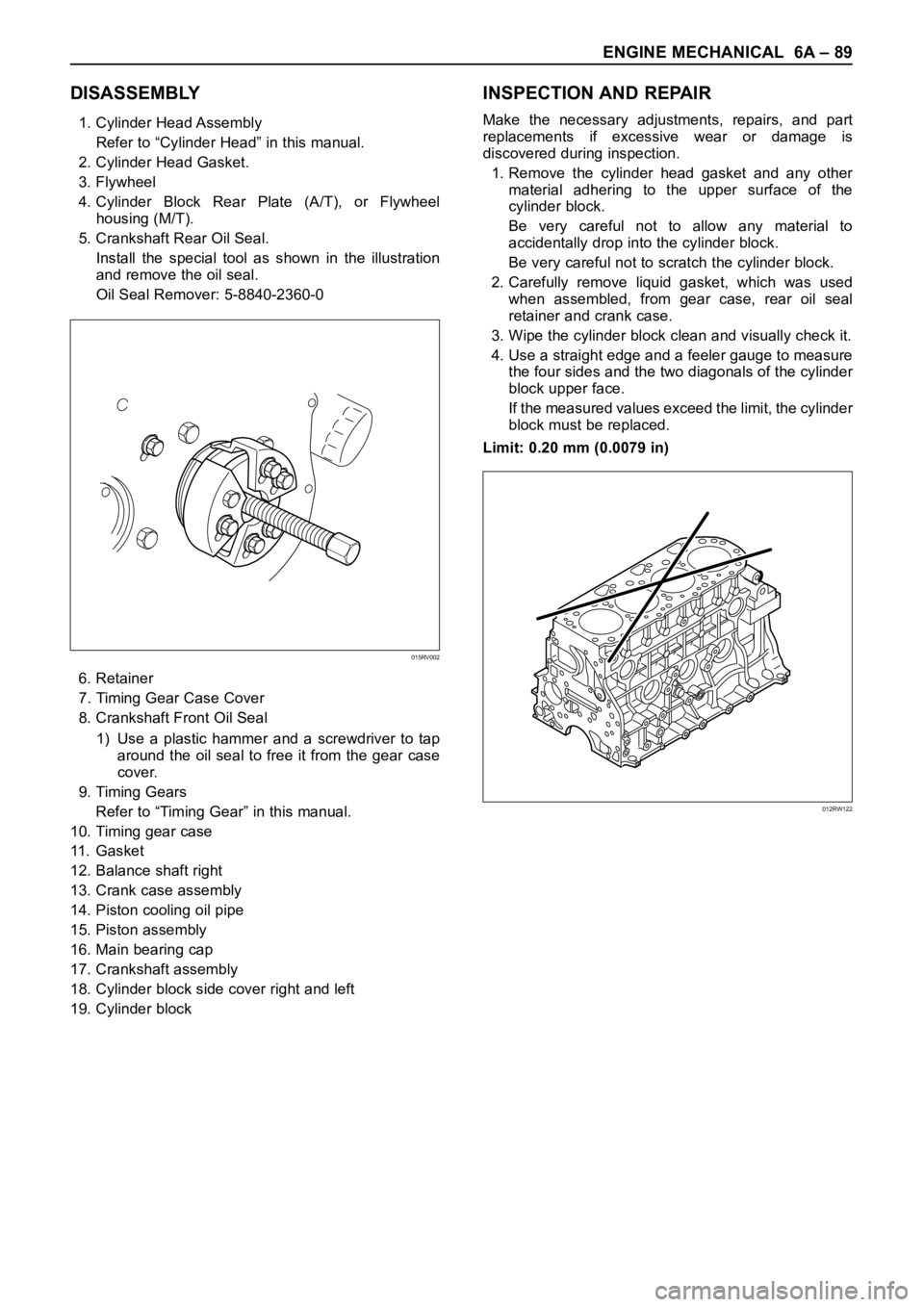
5. Crankshaft Rear Oil Seal.
Install the special tool as shown in the illustration
and remove the oil seal.
Oil Seal Remover: 5-8840-2360-0
6. Retainer
7. Timing Gear Case Cover
8. Crankshaft Front Oil Seal
1) Use a plastic hammer and a screwdriver to tap
around the oil seal to free it from the gear case
cover.
9. Timing Gears
Refer to “Timing Gear” in this manual.
10. Timing gear case
11 . G a s k e t
12. Balance shaft right
13. Crank case assembly
14. Piston cooling oil pipe
15. Piston assembly
16. Main bearing cap
17. Crankshaft assembly
18. Cylinder block side cover right and left
19. Cylinder block
INSPECTION AND REPAIR
Make the necessary adjustments, repairs, and part
replacements if excessive wear or damage is
discovered during inspection.
1. Remove the cylinder head gasket and any other
material adhering to the upper surface of the
cylinder block.
Be very careful not to allow any material to
accidentally drop into the cylinder block.
Be very careful not to scratch the cylinder block.
2. Carefully remove liquid gasket, which was used
when assembled, from gear case, rear oil seal
retainer and crank case.
3. Wipe the cylinder block clean and visually check it.
4. Use a straight edge and a feeler gauge to measure
the four sides and the two diagonals of the cylinder
block upper face.
If the measured values exceed the limit, the cylinder
block must be replaced.
Limit: 0.20 mm (0.0079 in)
015RV002
012RW122
Page 5363 of 6000

6A – 90 ENGINE MECHANICAL
Cylinder Bore Measurement
1. Use a cylinder gauge to measure the cylinder bore
measuring direction for thrust and radial at
measuring points.
Legend
Measuring Point 1; 20 mm
2; 90 mm
3; 160 mm
2. Select the right piston grade by the averaged
cylinder bore measurement (maximum and
minimum value eliminated).
Cylinder bore diameter mm(in)
Grade mark Standard
A 95.421 – 95.430 (3.7567 – 3.7571)
B 95.431 – 95.440 (3.7571 – 3.7575)
C 95.441 – 95.450 (3.7575 – 3.7579)
3. If measured values exceed the limit, replace or
adjust the cylinder block honing or boring.
Limit 95.950 mm (3.7776 in)
4. Boring of the cylinder bore is allowed until it is
0.5 mm (0.0197 in) diameter and oversized piston
is available as a service part.
Boring Cylinder Block
1. Use an oversized piston on the basis of above
mentioned cylinder using the largest inside
diameter.
2. Measure the piston outside diameter at right angles
with piston pin at a piston grade measuring point
69.75 mm (2.7461 in) from piston top surface and
calculate a inside diameter for cylinder boring.
3. Calculation of cylinder bore boring.
D + C – H (mm)
D; Outside diameter piston (mm)
C; Clearance between Cylinder bore and piston
0.092 – 0.110 mm (0.0036 – 0.0043 in)
H; Honing allowance
Less than 0.03 mm (0.0012 in)
The oversize pistons are available three grades.
4. Honing the cylinder bore after boring.
5. Measure cylinder bore after honing.
Difference between each cylinder bore
Less than 0.02 mm (0.0008 in)
Cylinder bore and piston grade (After boring) mm(in)
GradeOversize Piston Bore
Mark
Outside Diameter Diameter
A95.820 – 95.829 95.921 – 95.930
(3.7724 – 3.7728) (3.7764 – 3.7768)
B95.830 – 95.839 95.931 – 95.940
(3.7728 – 3.7732) (3.7768 – 3.7772)
C95.840 – 95.849 95.941 – 95.950
(3.7732 – 3.7736 ) (3.7772 – 3.7776)
REASSEMBLY
1. Cylinder Block
2. Piston Cooling Oil Pipe
1) Fix the cooling jet pipes with knock pins on the
cylinder block.
2) Install the oil pipe for piston cooling in the
cylinder block, tightening a relief valve (1) and
four joint bolts (2) to the specified torque.
If oil jet pipe is forcibly assembled, the end of oil
jet may bend. It could make it impossible to
supply oil to the piston cooling hole, sometimes
causing piston seizure.
Sufficient care should be taken to pipe assembly
work.
321
012RW117
Page 5370 of 6000
ENGINE COOLING 6B – 1
ENGINE COOLING
CONTENTS
General Description . . . . . . . . . . . . . . . . . . 6B–2
On-Vehicle Service . . . . . . . . . . . . . . . . . . . 6B–6
Water Pump . . . . . . . . . . . . . . . . . . . . . . 6B–6Thermostat . . . . . . . . . . . . . . . . . . . . . . . 6B–7
Radiator . . . . . . . . . . . . . . . . . . . . . . . . . 6B–9
Drive Belt Adjustment . . . . . . . . . . . . . . . 6B–11
Page 5371 of 6000
6B – 2 ENGINE COOLING
Legend
(1) Turbocharger
(2) Thermostat
(3) Reservoir Tank
(4) Radiator
(5) Bypass(6) Oil Cooler
(7) Cooling fan
(8) Water Pump
(9) Thermo Valve
(10) Car Heater
GENERAL DESCRIPTION
COOLANT FLOW
1
6
9
10
8
4
325
7
032RW001
The cooling system is a pressurized coolant forced
circulation type which consists of water pump,
thermostat, cooling fan, radiator and other components. The circulating coolant cools the lubricating oil in the oil
cooler and turbocharger.
Page 5372 of 6000
ENGINE COOLING 6B – 3
WAT E R P U M P
The coolant pump is a centrifugal impeller type and is
driven by V type drive belt.
Legend
(1) Roller Bearing
(2) Ball Bearing
(3) Seal Unit
THERMOSTAT
The thermostat is a wax pellet type with a jiggle valve
and is installed in the thermostat housing.
Legend
(1) Bolt
(2) Thermostat Housing
(3) Thermostat
(4) Intake Manifold
RADIATOR
The radiator is a tube type with corrugated fins. In order
to raise the boiling point of coolant, the radiator is fitted
with a cap in which the valve is operated under the
pressure.
1
3 2
PCD 60
A06RW024
1
2
3
4
032RW002
110RS001
Page 5373 of 6000

6B – 4 ENGINE COOLING
ANTI-FREEZE SOLUTION
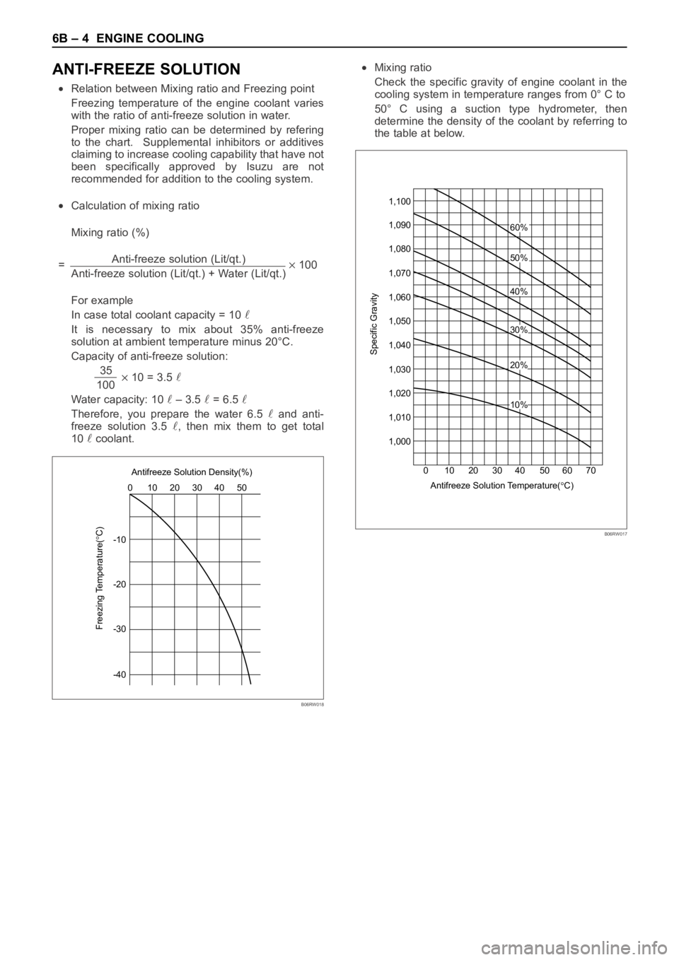
Relation between Mixing ratio and Freezing point
Freezing temperature of the engine coolant varies
with the ratio of anti-freeze solution in water.
Proper mixing ratio can be determined by refering
to the chart. Supplemental inhibitors or additives
claiming to increase cooling capability that have not
been specifically approved by Isuzu are not
recommended for addition to the cooling system.
Calculation of mixing ratio
Mixing ratio (%)
=Anti-freeze solution (Lit/qt.)
100
Anti-freeze solution (Lit/qt.) + Water (Lit/qt.)
For example
In case total coolant capacity = 10
It is necessary to mix about 35% anti-freeze
solution at ambient temperature minus 20°C.
Capacity of anti-freeze solution:
35
10 = 3.5 100
Water capacity: 10
– 3.5 = 6.5
Therefore, you prepare the water 6.5 and anti-
freeze solution 3.5
, then mix them to get total
10
coolant.
Mixing ratio
Check the specific gravity of engine coolant in the
cooling system in temperature ranges from 0° C to
50° C using a suction type hydrometer, then
determine the density of the coolant by referring to
the table at below.
-1010 0
Freezing Temperature(
C)
20 30 Antifreeze Solution Density(%)
40 50
-20
-30
-40
B06RW018
1,100
20 10 30 4060%
50%
40%
20%
10%
30%
Antifreeze Solution Temperature(
C) 50 60 70 0
Specific Gravity
1,090
1,080
1,070
1,060
1,050
1,040
1,030
1,020
1,010
1,000
B06RW017
Page 5374 of 6000

ENGINE COOLING 6B – 5
ENGINE COOLANT CHANGE
PROCEDURE
1. To change engine coolant, make sure that the
engine is cool.
WARNING:
When the coolant is heated to a high temperature,
be sure not to loosen or remove the radiator cap.
Otherwise you might get scalded by hot vapor or
boiling water. To open the radiator cap, put a piece
of thick cloth on the cap and loosen the cap slowly
to reduce the pressure once the coolant has
become cooler.
2. Open radiator cap and drain the cooling system by
loosening the drain valve on the radiator and on the
cylinder body.
NOTE: For best results it is suggested that the engine
cooling system be flushed at least once a year. It is
advisable to flush the interior of the cooling system
including the radiator before using anti-freeze
(ethylene-glycol based).
Replace damaged rubber hoses as the engine anti-
freeze coolant is liable to leak out even minor cracks.
Isuzu recommends using Isuzu genuine anti-freeze
(ethylene-glycol based) or equivalent, for the cooling
system and not add any inhibitors or additives.
CAUTION:
A failure to correctly fill the engine cooling system
in changing or topping off coolant may sometimes
cause the coolant to overflow from the filler neck
even before the engine and radiator are completely
full.
If the engine runs under this condition, shortage of
coolant may possibly result in engine overheating.
To avoid such trouble, the following precautions
should be taken in filling the system.
3. To refill engine coolant, pour coolant up to filler neck
using a filling hose which is smaller in outside
diameter than the filler neck. Otherwise air between
the filler neck and the filling hose will block entry,
preventing the system from completely filling up.
4. Keep a filling rate of 9 liter/min. or less. Filling over
this maximum rate may force air inside the engine
and radiator.
And also, the coolant overflow will increase, making
it difficult to determine whether or not the system is
completely full.
5. After filling the system full, pull out the filling hose
and check to see if air trapped in the system is
dislodged and the coolant level goes down. Should
the coolant level go down, repeat topping-off until
there is no more drop in the coolant level.
6. Directly after filling the radiator, fill the reservoir to
the maximum level.
7. Install and tighten radiator cap and start the engine.
After idling for 2 to 3 minutes, stop the engine and
reopen radiator cap. If the water level is lower,
replenish.WARNING:
When the coolant is heated to a high temperature,
be sure not to loosen or remove the radiator cap.
Otherwise you might get scalded by hot vapor or
boiling water. To open the radiator cap, put a piece
of thick cloth on the cap and loosen the cap slowly
to reduce the pressure once the coolant has
become cooler.
8. After tightening radiator cap, warm up the engine at
about 2,000 rpm.
Set heater adjustment to the highest temperature
position, and let the coolant circulate also into
heater water system.
9. Check to see the thermostat has opened by the
needle position of a water thermometer, conduct a
5-minute idle again and stop the engine.
10. When the engine has been cooled, check filler neck
for water level and replenish if required. Should
extreme shortage of coolant be found, check the
coolant system and reservoir tank hose for leakage.
11. Fill the coolant into the reservoir tank up to “MAX”
line.