1998 OPEL FRONTERA warning
[x] Cancel search: warningPage 3461 of 6000
SUPPLEMENTAL RESTRAINT SYSTEM 9J–24
NOTE: Ensure that the pigtail adapter is firmly seated into
the pretensioner seat belt assembly connector. Failure to
fully seat the connectors may leave the shorting bar
located in the pretensioner seat belt assembly connector
functioning (shorted) and may result in nondeployment of
the pretensioner seat belt assembly.
13. Separate the two banana plugs on the SRS
deployment harness.
NOTE: When the pretensioner seat belt deploys, the
rapid gas expansion will create a substantial noise. Notify
all people in the immediate area that you intend to deploy
the pretensioner seat belt.
WARNING: DEPLOYMENT HARNESS SHALL
REMAIN SHORTED AND NOT BE CONNECTED TO A
POWER SOURCE UNTIL THE PRETENSIONER SEAT
BELT IS TO BE DEPLOYED. THE PRETENSIONER
SEAT BELT ASSEMBLY WILL IMMEDIATELY
DEPLOY THE PRETENSIONER SEAT BELT WHEN A
POWER SOURCE IS CONNECTED TO IT.
CONNECTING THE DEPLOYMENT HARNESS TO
THE POWER SOURCE SHOULD ALWAYS BE THE
LAST STEP IN THE PRETENSIONER SEAT BELT
ASSEMBLY DEPLOYMENT PROCEDURE. FAILURE
TO FOLLOW PROCEDURES IN THE ORDER LISTED
MAY RESULT IN PERSONAL INJURY.
14. Connect the SRS deployment harness wires to the
power source to immediately deploy the pretensioner
seat belt. Recommended application: 12 volts
minimum, 2 amps minimum. A vehicle battery is
suggested.
15. Disconnect the SRS deployment harness from the
power source.
16. Short the two SRS deployment harness leads
together by fully seating one banana plug into the
other.
17. In the unlikely event that the pretensioner seat belt
assembly did not deploy after following these
procedures, proceed immediately with Steps 21
through 24. If the pretensioner seat belt assembly did
deploy, proceed with Steps 15 through 20.
18.
WARNING: SAFETY PRECAUTIONS MUST BE
OBSERVED WHEN HANDING A DEPLOYED
PRETENSIONER SEAT BELT ASSEMBLY. AFTER
DEPLOYMENT, THE METAL SURFACES OF THE
PRETENSIONER SEAT BELT ASSEMBLY WILL BE
VERY HOT. ALLOW THE INFLATOR MODULE TO
COOL BEFORE HANDLING ANY METAL PORTION
OF IT. DO NOT PLACE THE DEPLOYED
PRETENSIONER SEAT BELT ASSEMBLY NEAR ANY
FLAMMABLE OBJECTS. FAILURE TO FOLLOW
PROCEDURES MAY RESULT IN FIRE OR PERSONAL
INJURY.
AFTER A DRIVER PRETENSIONER SEAT BELT
ASSEMBLY HAS BEEN DEPLOYED, THE METAL
CANISTER AND SURROUNDING AREAS OF THE
DRIVER PRETENSIONER SEAT BELT ASSEMBLY
WILL BE VERY HOT. DO NOT TOUCH THE METAL
AREAS OF THE PRETENSIONER SEAT BELT
ASSEMBLY FOR ABOUT TEN MINUTES AFTER
DEPLOYMENT. IF THE DEPLOYED PRETENSIONERSEAT BELT ASSEMBLY MUST BE MOVED BEFORE
IT IS COOL, WEAR GLOVES AND HANDLE BY THE
PRETENSIONER SEAT BELT OR TRIM COVER.
19. Disconnect the pigtail adapter from the pretensioner
seat belt assembly as soon after deployment as
possible. This will prevent damage to the pigtail
adapter or SRS deployment harness due to possible
contact with the hot pretensioner seat belt assembly
canister. The pigtail adapter can be reused. They
should, however, be inspected for damage after each
deployment and replaced if necessary.
20. Dispose of the deployed pretensioner seat belt
assembly through normal refuse channels after it has
cooled for at least 30 minutes.
21. Wash your hands with mild soap and water afterward.
NOTE: The remaining steps are to be followed in the
unlikely event that the pretensioner seat belt assembly
did not deploy after following these procedures.
22. Ensure that the SRS deployment harness has been
disconnected from the power source and that its two
banana plugs have been shorted together by fully
seating one banana plug into the other.
23. Disconnect the pigtail adapter from the pretensioner
seat belt assembly.
24. Remove the undeployed pretensioner seat belt from
the special tool.
WARNING: W H E N S TO R I N G A L I V E
PRETENSIONER SEAT BELT ASSEMBLY OR WHEN
LEAVING A LIVE INFLATOR MODULE UNATTENDED
ON A BENCH OR OTHER SURFACE, ALWAYS PUT
THE PRETENSIONER SEAT BELT HORIZONTAL
PLACE. THIS IS NECESSARY SO THAT A FREE
SPACE IS PROVIDED TO ALLOW THE
PRETENSIONER SEAT BELT TO SHRINK IN THE
UNLIKELY EVENT OF ACCIDENTAL DEPLOYMENT.
FAILURE TO FOLLOW PROCEDURES MAY RESULT
IN PERSONAL INJURY.
25.Temporarily store the pretensioner seat belt
assembly with its deployment device facing up, away
from the surface upon which it rests.
Deployment Inside Vehicle (Pretensioner
Seat Belt Vehicle Scrapping Procedure)
Deployment inside vehicle is proper when the vehicle is to
be destroyed. This includes, but is not limited to, the
following situations:
1. The vehicle has completed its useful life.
2. The vehicle has been damaged beyond repair in a
nondeployment type accident.
3. The vehicle has been stripped or damaged beyond
repair in a theft.
NOTE: The vehicle will be salvaged for component parts
to be used on a vehicle with a different Vehicle
Identification Number (VIN) as opposed to being rebuilt
as same VIN. Never use pretensioner seat belt
components from another vehicle.
WARNING: FAILURE TO FOLLOW PROCEDURES IN
THE ORDER LISTED COULD RESULT IN PERSONAL
INJURY. NEVER CONNECT DEPLOYMENT WIRES
Page 3462 of 6000
SUPPLEMENTAL RESTRAINT SYSTEM9J–25
TO ANY POWER SOURCE BEFORE CONNECTING
DEPLOYMENT WIRES TO THE PRETENSIONER
SEAT BELT ASSEMBLY LEADS. DEPLOYMENT
WIRES SHALL REMAIN SHORTED AND NOT BE
CONNECTED TO A POWER SOURCE UNTIL THE
PRETENSIONER SEAT BELT IS TO BE DEPLOYED.
THE PRETENSIONER SEAT BELT ASSEMBLY WILL
IMMEDIATELY DEPLOY THE PRETENSIONER SEAT
BELT WHEN A POWER SOURCE IS CONNECTED TO
IT. WEAR SAFETY GLASSES THROUGHOUT THIS
ENTIRE DEPLOYMENT AND DISPOSAL
PROCEDURE.
1. Turn ignition switch to “LOCK,” remove key and put
on safety glasses.
2. Remove all loose objects from front seats.
3. Disconnect pretensioner seat belt assembly, yellow
2–pin connector located at the base of the seat.
4. Prepare SRS deployment harness.
5. Short the two SRS deployment harness leads
together by fully seating one banana plug into the
other.
6. Deployment harness shall remain shorted and not be
connected to a power source until the pretensioner
seat belt is to be deployed.
7. Route deployment harness out the driver side of the
vehicle.
8. Verify that the inside of the vehicle and the area
surrounding the vehicle are clear of all people and
loose or flammable objects.
9. Stretch the SRS deployment harness to their full
length.
10. Connect the deployment harness to the pretensioner
seat belt assembly, yellow 2-pin connector at the
base of the seat.
WARNING: DEPLOYMENT WIRES SHALL REMAIN
SHORTED AND NOT BE CONNECTED TO A POWER
SOURCE UNTIL THE PRETENSIONER SEAT BELT IS
TO BE DEPLOYED. THE PRETENSIONER SEAT
BELT ASSEMBLY WILL IMMEDIATELY DEPLOY THE
PRETENSIONER SEAT BELT WHEN A POWER
SOURCE IS CONNECTED TO IT. CONNECTING THE
DEPLOYMENT WIRES TO THE POWER SOURCE
SHOULD ALWAYS BE THE FINAL STEP IN THE
PRETENSIONER SEAT BELT ASSEMBLY
DEPLOYMENT PROCEDURE. FAILURE TO FOLLOW
PROCEDURES IN THE ORDER LISTED COULD
RESULT IN PERSONAL INJURY.
11. Notify all people in the immediate area that you intend
to deploy the pretensioner seat belt. The deployment
will be accompanied by a substantial noise which may
startle the uninformed.
12. Separate the two banana plugs on the SRS
deployment harness.
NOTE: When the pretensioner seat belt deploys, the
rapid gas expansion will create a substantial noise. Notify
all people in the immediate area that you intend to deploy
the pretensioner seat belt.13. Connect the SRS deployment harness wires to a
power source to immediately deploy the pretensioner
seat belt assembly. Recommended application: 12
volts minimum, 2 amps minimum. A vehicle battery is
suggested.
WARNING: DEPLOYMENT WIRES SHALL REMAIN
SHORTED AND NOT BE CONNECTED TO A POWER
SOURCE UNTIL THE PRETENSIONER SEAT BELT IS
TO IS TO BE DEPLOYED. THE PRETENSIONER
SEAT BELT ASSEMBLY WILL IMMEDIATELY
DEPLOY THE PRETENSIONER SEAT BELT WHEN A
POWER SOURCE IS CONNECTED TO IT.
CONNECTING THE DEPLOYMENT WIRES SHOULD
ALWAYS BE THE FINAL STEP IN THE
PRETENSIONER SEAT BELT ASSEMBLY
DEPLOYMENT PROCEDURE. FAILURE TO FOLLOW
PROCEDURES IN THE ORDER LISTED COULD
RESULT IN PERSONAL INJURY.
14. Short the two SRS deployment harness leads
together by fully seating one banana plug into the
other.
15. Disconnect the deployment harness to the
pretensioner seat belt assembly, yellow 2-pin
connector at the base of the seat.
16. In the unlikely event that the pretensioner seat belt
assembly did not deploy after following these
procedures, proceed immediately with Steps 18
through 19. If the pretensioner seat belt assembly
deployed as intended, proceed with Steps 14 through
17.
17. With both air bags and pretensioner seat belt
deployed, the vehicle may be scrapped in the same
manner as a non–SRS equipped vehicle.
NOTE: The remaining steps are to be followed in the
unlikely event that the pretensioner seat belt assembly
did not deploy after following these procedures.
18. Remove the undeployed pretensioner seat belt
assembly (s) from the vehicle. For pretensioner seat
belt assembly refer to in the “Pretensioner Seat Belt
Assembly Removal” in this manual.
19.Temporarily store the pretensioner seat belt
assembly with the deployment device facing up, away
from the surface upon which it rests.
Page 3463 of 6000
SUPPLEMENTAL RESTRAINT SYSTEM 9J–26
Special Tools
WARNING: TO AVOID DEPLOYMENT WHEN
TROUBLESHOOTING THE SRS, DO NOT USE
ELECTRICAL TEST EQUIPMENT SUCH AS A
BATTERY–POWERED OR AC–POWERED
VOLTMETER, OHMMETER, ETC., OR ANY TYPE OF
ELECTRICAL EQUIPMENT OTHER THAN THAT
SPECIFIED IN THIS MANUAL. DO NOT USE A
NONPOWERED PROBE–TYPE TESTER.
INSTRUCTIONS IN THIS MANUAL MUST BE
FOLLOWED CAREFULLY, OTHERWISE PERSONAL
INJURY MAY RESULT.
5–8840–2421–0 SRS Driver/Passenger
Load Tool
901RS146The SRS Driver/Passenger Load Tool 5–8840–2421–0 is
used only when called for in this section. It is used as a
diagnostic aid and safety device to prevent inadvertent air
bag assembly deployment.
The load tool has three yellow connectors attached to its
case.
The three small connectors are electrically functional and
serve as resistive load substitutions.
No more than two connectors are used at any time. One
of the small connectors is used to substitute for the load of
the driver air bag assembly when it is connected at the top
of the column to the SRS coil assembly. Another small
connector is used to substitute for the load of the driver air
bag assembly and the SRS coil assembly when it is
connected at the base of the column to the SRS wiring
harness. The third small connector is used to substitute
for the load of the passenger air bag assembly and
pretensioner seat belt assembly when connected to the
passenger air bag assembly and pretensioner seat belt
assembly harness connector.
By substituting the resistance of the load tool when called
for, a determination can be made as to whether an inflator
circuit component is causing system malfunction and
which component is causing the malfunction. The loadtool should be used only when specifically called for in the
diagnostic procedures.
NOTE: If comand to use 5–8840–2421–0 load tool when
repair the pretensioner seat belt, connect load tool
connector to use for driver air bag and/or passenger air
bag connector.
5–8840–0285–0 DVM
901RS153The 5–8840–0285–0 DVM is the preferred DVM for use in
SRS diagnosis and repair. However, 5–8840–0366–0
may be used if 5–8840–0285–0 is not available. No other
DVMs are approved for SRS diagnosis and repair.
Scan Tool
901RW176The Tech 2 is used to read and clear SRS Diagnostic
Trouble Codes (DTCs). Refer to the Tech 2 Operators,
Manual for specific information on how to use the Tech 2.
Page 3467 of 6000
SUPPLEMENTAL RESTRAINT SYSTEM 9J–30
Service Precautions for SRS
Component Service
CAUTION: When fasteners are removed, always
reinstall them at the same location from which they
were removed. If a fastener needs to be replaced, use
the correct part number fastener for that application.
If the correct part number fastener is not available, a
fastener of equal size and strength (or stronger) may
be used. fasteners that are not reused, and those
requiring thread locking compound will be called
out. The correct torque value must be used when
installing fasteners that require it. If the above
conditions are not followed, parts or system damage
could result.
WARNING: WHEN PERFORMING SERVICE ON OR
AROUND SRS COMPONENTS OR SRS WIRING,
FOLLOW THE PROCEDURES LISTED BELOW TO
TEMPORARILY DISABLE THE SRS. FAILURE TO
FOLLOW PROCEDURES COULD RESULT IN
POSSIBLE AIR BAG DEPLOYMENT, PERSONAL
INJURY OR OTHERWISE UNNEEDED SRS REPAIRS.
The SDM in Driver–Passenger SRS can maintain
sufficient voltage to cause a deployment for up to 15
seconds after the ignition switch is turned “OFF,” the
battery is disconnected, or the fuse powering the SDM is
removed.
Many of the service procedures require removal of the
“C–21” fuse, and disconnection of the air bag assembly
from the deployment loop to avoid an accidental
deployment. If the air bag assembly is disconnected from
the deployment loop as noted in the “Disabling the SRS”
procedure that follows, service can begin immediately
without waiting for the 15 second time period to expire.
Disabling The SRS
Removal
Turn the ignition switch to “OFF” and turn the steering
wheel so that the vehicle’s wheels are pointing straight
ahead.
1. Remove SRS fuse “C–21” from left dash side lower
fuse block or disconnect battery.
2. Disconnect yellow 2–pin connector at the base of
steering column.
3 . R e m o v e g l o v e b o x a s s e m b l y ; R e f e r t o “ P a s s e n g e r a i r
bag assembly replacement” in this section.
4. Disconnect passenger air bag assembly yellow 2–pin
connector behind the glove box assembly.
CAUTION: W i t h t h e “ C – 2 1 ” f u s e r e m o v e d a n d
ignition switch “ON,” the “AIR BAG” warning lamp
will be “ON.” This is normal operation and does not
indicate an SRS malfunction.
Enabling The SRS
Installation
Turn ignition switch to “LOCK” and remove key.
1. Connect yellow 2–pin connector passenger air bag
assembly.2. Install glove box assembly. Refer to “Passenger Air
Bag Assembly Replacement” in this section.
3. Connect yellow 2–pin connector at the base of the
steering column.
4. Install “AIR BAG” fuse “C–21” to left dash side lower
fuse block or connect battery.
Turn ignition switch to “ON” and verify that the “AIR BAG”
warning lamp turn on 3.5 seconds and then turns “OFF.” If
it does not operate as described, perform the “SRS
Diagnostic System Check” in this section.
Handling / Installation / Diagnosis
1. Air bag assembly should not be subjected to
temperatures above 93
C (200F).
2. Air bag assembly, and SDM should not be used if they
have been dropped from a height of 100 centimeters
(3.28 feet) or more.
3. When a SDM is replaced, it must be oriented with the
arrow on the SDM pointing toward the front of the
vehicle. It is very important for the SDM to be located
flat on the mounting surface, parallel to the vehicle
datum line. It is important that the SDM mounting
surface is free of any dirt or other foreign material.
4. Do not apply power to the SRS unless all components
are connected or a diagnostic chart requests it, as
this will set a diagnostic trouble code.
5. The “SRS Diagnostic System Check” must be the
starting point of any SRS diagnostics. The “SRS
Diagnostic System Check” will verify proper “AIR
BAG” warning lamp operation and will lead you to the
correct chart to diagnose any SRS malfunctions.
Bypassing these procedures may result in extended
diagnostic time, incorrect diagnosis, and incorrect
parts replacements.
Inspections Required After An Accident
CAUTION: C e r t a i n S R S c o m p o n e n t s m u s t b e
replaced after a frontal crash involving air bag
deployment.
In all types of accidents regardless of “Air Bag”
deployment, visually inspect all of the following
components and replace as required:
— Driver air bag assembly
— Passenger air bag assembly
— Driver pretensioner assembly
— Passenger pretensioner assembly
— Steering wheel
— SRS coil assembly
— Steering column
— Knee bolster and instrument panel mounting
attachments
— Driver seat and belt
— Passenger seat and belt
—SDM
SDM always should be checked according to “SDM
Replacement Guidelines.”
Page 3470 of 6000
SUPPLEMENTAL RESTRAINT SYSTEM9J–33
Sensing And Diagnostic Module (SDM)
Service Precautions
WARNING: DURING SERVICE PROCEDURES, BE
VERY CAREFUL WHEN HANDLING SDM. NEVER
STRIKE OR JAR SDM. UNDER SOME
CIRCUMSTANCES, IT COULD CAUSE
DEPLOYMENT AND RESULT IN PERSONAL INJURY
OR IMPROPER OPERATION OF THE
SUPPLEMENTAL RESTRAINT SYSTEM (SRS) . SDM
MOUNTING BRACKET BOLTS MUST BE
CAREFULLY TORQUED TO ASSURE PROPER
OPERATION. NEVER POWER UP THE SRS WHEN
SDM IS NOT RIGIDLY ATTACHED TO THE VEHICLE.
THE SDM COULD BE ACTIVATED WHEN POWERED
WHILE NOT RIGIDLY ATTACHED TO THE VEHICLE
WHICH COULD CAUSE DEPLOYMENT AND RESULT
IN PERSONAL INJURY.
WARNING: PROPER OPERATION OF THE SENSING
AND DIAGNOSTIC MODULE (SDM) REQUIRES THE
SDM TO BE RIGIDLY ATTACHED TO THE VEHICLE
STRUCTURE AND THAT THE ARROW ON THE
SENSOR BE POINTING TOWARD THE FRONT OF
THE VEHICLE.
SDM is specifically calibrated and is keyed to the SDM
location SRS wiring harness. Caution should be used to
ensure proper location of the SDM. The keying of the
SDM to its location and wiring harness connectors should
never be modified in the field.
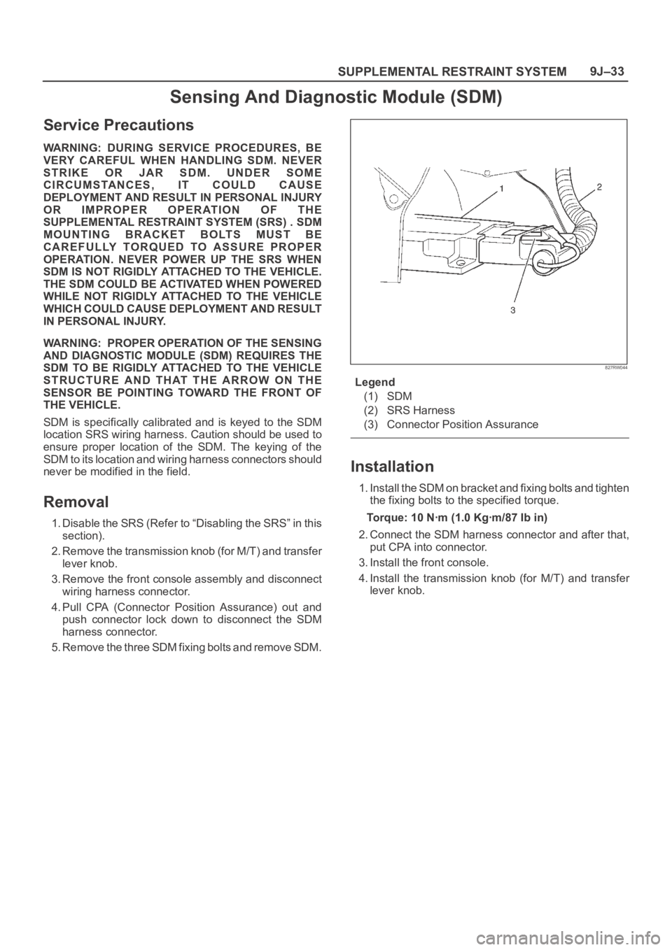
Removal
1. Disable the SRS (Refer to “Disabling the SRS” in this
section).
2. Remove the transmission knob (for M/T) and transfer
lever knob.
3. Remove the front console assembly and disconnect
wiring harness connector.
4. Pull CPA (Connector Position Assurance) out and
push connector lock down to disconnect the SDM
harness connector.
5. Remove the three SDM fixing bolts and remove SDM.
827RW044
Legend
(1) SDM
(2) SRS Harness
(3) Connector Position Assurance
Installation
1. Install the SDM on bracket and fixing bolts and tighten
the fixing bolts to the specified torque.
Torque: 10 Nꞏm (1.0 Kgꞏm/87 Ib in)
2. Connect the SDM harness connector and after that,
put CPA into connector.
3. Install the front console.
4. Install the transmission knob (for M/T) and transfer
lever knob.
Page 3472 of 6000
SUPPLEMENTAL RESTRAINT SYSTEM9J–35
Driver Air Bag Assembly
Service Precautions
WARNING: SAFETY PRECAUTIONS MUST BE
FOLLOWED WHEN HANDLING A DEPLOYED AIR
BAG ASSEMBLY. AFTER DEPLOYMENT, THE AIR
BAG ASSEMBLY SURFACE MAY CONTAIN A SMALL
AMOUNT OF SODIUM HYDROXIDE, A BY–PRODUCT
OF THE DEPLOYMENT REACTION, THAT IS
IRRITATING TO THE SKIN AND EYES. MOST OF THE
POWER ON THE AIR BAG ASSEMBLY IS
HARMLESS. AS A PRECAUTION, WEAR GLOVES
AND SAFETY GLASSES WHEN HANDLING A
DEPLOYED AIR BAG ASSEMBLY, AND WASH YOUR
HANDS WITH MILD SOAP AND WATER
AFTERWARDS.
WARNING: WHEN CARRYING A LIVE AIR BAG
ASSEMBLY, MAKE SURE THE BAG AND TRIM
COVER ARE POINTED AWAY FROM YOU. NEVER
CARRY AIR BAG ASSEMBLY BY THE WIRES OR
CONNECTOR ON THE UNDERSIDE OF MODULE. IN
THE CASE OF AN ACCIDENTAL DEPLOYMENT, THE
BAG WILL THEN DEPLOY WITH MINIMAL CHANCE
OF INJURY. WHEN PLACING ALIVE AIR BAG
ASSEMBLY ON A BENCH OR OTHER SURFACE,
ALWAYS FACE BAG AND TRIM COVER UP, AWAY
FROM THE SURFACE. NEVER REST A STEERING
COLUMN ASSEMBLY ON THE STEERING WHEEL
WITH THE AIR BAG ASSEMBLY FACE DOWN AND
COLUMN VERTICAL. THIS IS NECESSARY SO THAT
A FREE SPACE IS PROVIDED TO ALLOW THE AIR
BAG ASSEMBLY TO EXPAND IN THE UNLIKELY
EVENT OF ACCIDENTAL DEPLOYMENT.
OTHERWISE, PERSONAL INJURY COULD RESULT.
NOTE: In the event deployment has occurred, inspect
coil assembly wire for any signs of scorching, melting or
any other damage due to excessive heat. If the coil has
been damaged, replace it.
Removal
1. Disable the SRS (Refer to “Disabling the SRS” in this
section).
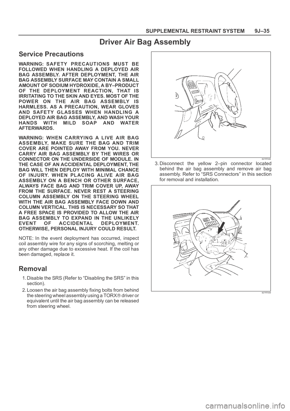
2. Loosen the air bag assembly fixing bolts from behind
the steering wheel assembly using a TORX
d r i v e r o r
equivalent until the air bag assembly can be released
from steering wheel.
827RT008
3. Disconnect the yellow 2–pin connector located
behind the air bag assembly and remove air bag
assembly. Refer to “SRS Connectors” in this section
for removal and installation.
827RT009
Page 3474 of 6000
SUPPLEMENTAL RESTRAINT SYSTEM9J–37
Steering Wheel
Service Precautions
WARNING: SAFETY PRECAUTIONS MUST BE
FOLLOWED WHEN HANDLING A DEPLOYED AIR
BAG ASSEMBLY. AFTER DEPLOYMENT, THE AIR
BAG ASSEMBLY SURFACE MAY CONTAIN A SMALL
AMOUNT OF SODIUM HYDROXIDE, A BY–PRODUCT
OF THE DEPLOYMENT REACTION, THAT IS
IRRITATING TO THE SKIN AND EYES. MOST OF THE
POWER ON THE AIR BAG ASSEMBLY IS
HARMLESS. AS A PRECAUTION, WEAR GLOVES
AND SAFETY GLASSES WHEN HANDLING A
DEPLOYED AIR BAG ASSEMBLY, AND WASH YOUR
HANDS WITH MILD SOAP AND WATER
AFTERWARDS.
WARNING: WHEN CARRYING A LIVE AIR BAG
ASSEMBLY, MAKE SURE THE BAG AND TRIM
COVER ARE POINTED AWAY FROM YOU. NEVER
CARRY AIR BAG ASSEMBLY BY THE WIRES OR
CONNECTOR ON THE UNDERSIDE OF MODULE. IN
THE CASE OF AN ACCIDENTAL DEPLOYMENT, THE
BAG WILL THEN DEPLOY WITH MINIMAL CHANCE
OF INJURY. WHEN PLACING ALIVE AIR BAG
ASSEMBLY ON A BENCH OR OTHER SURFACE,
ALWAYS FACE BAG AND RIM COVER UP, AWAY
FROM THE SURFACE. NEVER REST A STEERING
COLUMN ASSEMBLY ON THE STEERING WHEEL
WITH THE AIR BAG ASSEMBLY FACE DOWN AND
COLUMN VERTICAL. THIS IS NECESSARY SO THAT
A FREE SPACE IS PROVIDED TO ALLOW THE AIR
BAG ASSEMBLY TO EXPAND IN THE UNLIKELY
EVENT OF ACCIDENTAL DEPLOYMENT.
OTHERWISE, PERSONAL INJURY COULD RESULT.
NOTE: In the event deployment has occurred, inspect
coil assembly wire for any signs of scorching, melting or
any other damage due to excessive heat. If the coil has
been damaged, replace it.
Removal
1. Disable the SRS (Refer to “Disabling the SRS” in this
section).
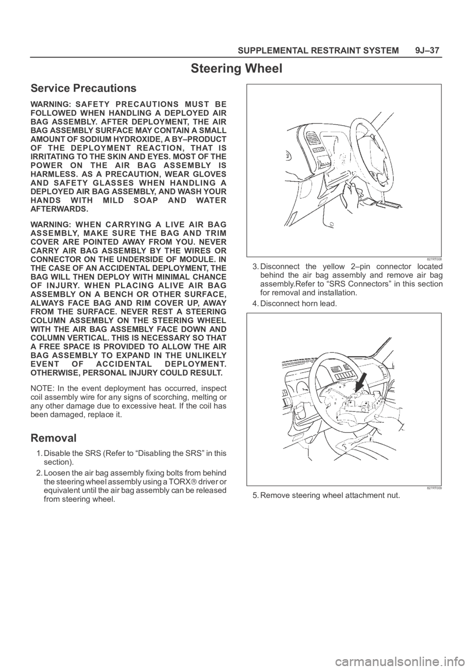
2. Loosen the air bag assembly fixing bolts from behind
the steering wheel assembly using a TORX
d r i v e r o r
equivalent until the air bag assembly can be released
from steering wheel.
827RT008
3. Disconnect the yellow 2–pin connector located
behind the air bag assembly and remove air bag
assembly.Refer to “SRS Connectors” in this section
for removal and installation.
4. Disconnect horn lead.
827RT009
5. Remove steering wheel attachment nut.
Page 3476 of 6000
SUPPLEMENTAL RESTRAINT SYSTEM9J–39
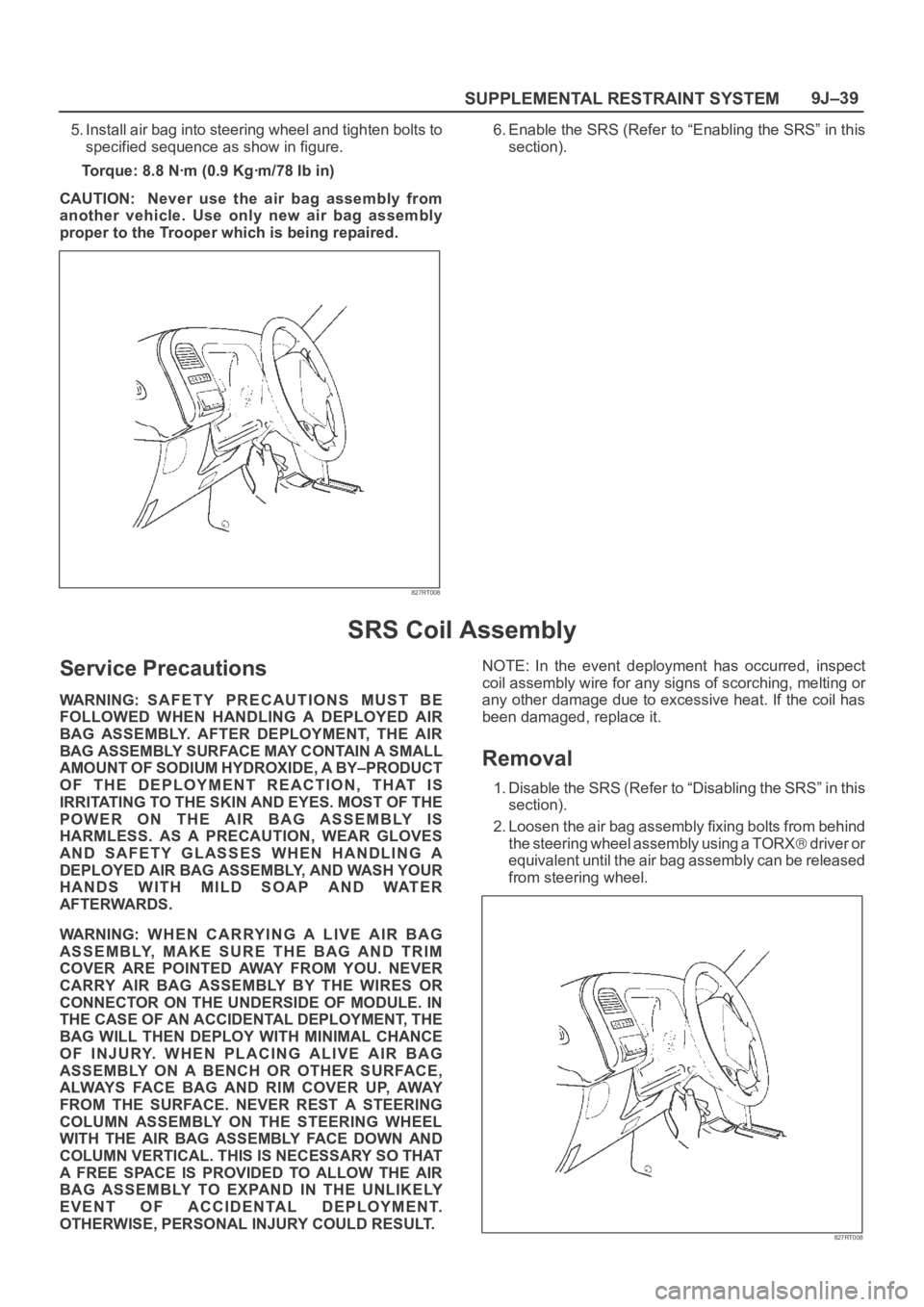
5. Install air bag into steering wheel and tighten bolts to
specified sequence as show in figure.
Torque: 8.8 Nꞏm (0.9 Kgꞏm/78 Ib in)
CAUTION: Never use the air bag assembly from
another vehicle. Use only new air bag assembly
proper to the Trooper which is being repaired.
827RT008
6. Enable the SRS (Refer to “Enabling the SRS” in this
section).
SRS Coil Assembly
Service Precautions
WARNING: SAFETY PRECAUTIONS MUST BE
FOLLOWED WHEN HANDLING A DEPLOYED AIR
BAG ASSEMBLY. AFTER DEPLOYMENT, THE AIR
BAG ASSEMBLY SURFACE MAY CONTAIN A SMALL
AMOUNT OF SODIUM HYDROXIDE, A BY–PRODUCT
OF THE DEPLOYMENT REACTION, THAT IS
IRRITATING TO THE SKIN AND EYES. MOST OF THE
POWER ON THE AIR BAG ASSEMBLY IS
HARMLESS. AS A PRECAUTION, WEAR GLOVES
AND SAFETY GLASSES WHEN HANDLING A
DEPLOYED AIR BAG ASSEMBLY, AND WASH YOUR
HANDS WITH MILD SOAP AND WATER
AFTERWARDS.
WARNING: WHEN CARRYING A LIVE AIR BAG
ASSEMBLY, MAKE SURE THE BAG AND TRIM
COVER ARE POINTED AWAY FROM YOU. NEVER
CARRY AIR BAG ASSEMBLY BY THE WIRES OR
CONNECTOR ON THE UNDERSIDE OF MODULE. IN
THE CASE OF AN ACCIDENTAL DEPLOYMENT, THE
BAG WILL THEN DEPLOY WITH MINIMAL CHANCE
OF INJURY. WHEN PLACING ALIVE AIR BAG
ASSEMBLY ON A BENCH OR OTHER SURFACE,
ALWAYS FACE BAG AND RIM COVER UP, AWAY
FROM THE SURFACE. NEVER REST A STEERING
COLUMN ASSEMBLY ON THE STEERING WHEEL
WITH THE AIR BAG ASSEMBLY FACE DOWN AND
COLUMN VERTICAL. THIS IS NECESSARY SO THAT
A FREE SPACE IS PROVIDED TO ALLOW THE AIR
BAG ASSEMBLY TO EXPAND IN THE UNLIKELY
EVENT OF ACCIDENTAL DEPLOYMENT.
OTHERWISE, PERSONAL INJURY COULD RESULT.NOTE: In the event deployment has occurred, inspect
coil assembly wire for any signs of scorching, melting or
any other damage due to excessive heat. If the coil has
been damaged, replace it.
Removal
1. Disable the SRS (Refer to “Disabling the SRS” in this
section).
2. Loosen the air bag assembly fixing bolts from behind
the steering wheel assembly using a TORX
d r i v e r o r
equivalent until the air bag assembly can be released
from steering wheel.
827RT008