Page 5673 of 6000

6G – 6 ENGINE LUBRICATION
OIL COOLER ASSEMBLY
REMOVAL
1. Disconnect battery ground cable.
2. Drain engine coolant.
3. Remove front exhaust pipe.
4. Remove heat protector.
5. Remove exhaust valve assembly.
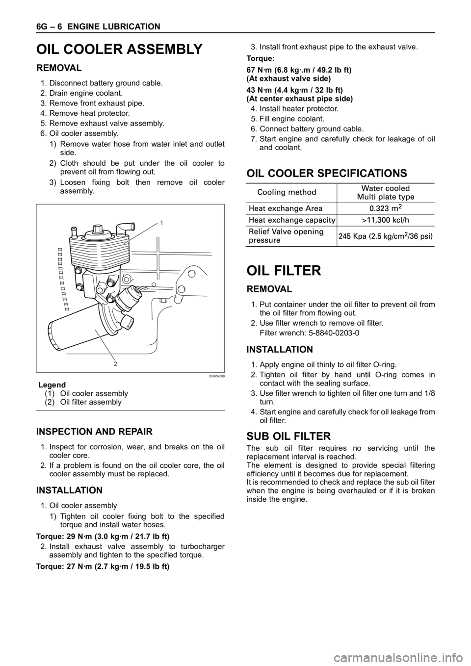
6. Oil cooler assembly.
1) Remove water hose from water inlet and outlet
side.
2) Cloth should be put under the oil cooler to
prevent oil from flowing out.
3) Loosen fixing bolt then remove oil cooler
assembly.
Legend
(1) Oil cooler assembly
(2) Oil filter assembly
INSPECTION AND REPAIR
1. Inspect for corrosion, wear, and breaks on the oil
cooler core.
2. If a problem is found on the oil cooler core, the oil
cooler assembly must be replaced.
INSTALLATION
1. Oil cooler assembly
1) Tighten oil cooler fixing bolt to the specified
torque and install water hoses.
Torque: 29 Nꞏm (3.0 kgꞏm / 21.7 lb ft)
2. Install exhaust valve assembly to turbocharger
assembly and tighten to the specified torque.
Torque: 27 Nꞏm (2.7 kgꞏm / 19.5 lb ft)3. Install front exhaust pipe to the exhaust valve.
To r q u e :
67 Nꞏm (6.8 kgꞏ.m / 49.2 lb ft)
(At exhaust valve side)
43 Nꞏm (4.4 kgꞏm / 32 lb ft)
(At center exhaust pipe side)
4. Install heater protector.
5. Fill engine coolant.
6. Connect battery ground cable.
7. Start engine and carefully check for leakage of oil
and coolant.
OIL COOLER SPECIFICATIONS
OIL FILTER
REMOVAL
1. Put container under the oil filter to prevent oil from
the oil filter from flowing out.
2. Use filter wrench to remove oil filter.
Filter wrench: 5-8840-0203-0
INSTALLATION
1. Apply engine oil thinly to oil filter O-ring.
2. Tighten oil filter by hand until O-ring comes in
contact with the sealing surface.
3. Use filter wrench to tighten oil filter one turn and 1/8
turn.
4. Start engine and carefully check for oil leakage from
oil filter.
SUB OIL FILTER
The sub oil filter requires no servicing until the
replacement interval is reached.
The element is designed to provide special filtering
efficiency until it becomes due for replacement.
It is recommended to check and replace the sub oil filter
when the engine is being overhauled or if it is broken
inside the engine.
1
2
050RW009
Page 5687 of 6000
6J – 10 INDUCTION
INTAKE MANIFOLD
REMOVAL
1. Drain engine coolant and remove water hose from
thermostat housing
2. Remove intercooler assembly.
3. Remove bracket fixing bolt of oil level gauge guide
tube.
4. Remove PCV hose.
5. Remove hoses from EGR valve, EGR vacuum
sensor and outlet of heater unit.
6. Disconnect harness connector from MAP sensor,
EGR vacuum sensor, ETC sensor, Water
temperature unit, IAT sensor and EVRV.
7. Remove high pressure oil pipe.
8. Remove two way check valve.
9. Remove fuel pipe.
10. Remove fixing bolts and nuts of intake manifold,
remove intake manifold assembly.
Legend
(1) Intake manifold
(2) Fixing portion of throttle valve
(3) EGR passage
(4) EGR valve
2
3
4
1
Legend
(1) Intake Manifold
(2) Throttle Valve Assembly
(3) EGR Valve
(4) Gasket
025RW022
3124
025RW031
Page 5688 of 6000

INDUCTION 6J – 11
INSPECTION AND RAPAIR
1. Visually check for cracks/clogs inside intake
manifold.
2. If foreign material is observed, it should be taken
out, and if there are some cracks on the intake
manifold, it must be replaced.
INSTALLATION
1. Install the intake manifold assembly, tighten bolts
and to the specified torque.
Torque: 20 Nꞏm (2.0 kgꞏm / 14.5 lb ft) for bolt
Torque: 20 Nꞏm (2.0 kgꞏm / 14.5 lb ft) for nut
2. Install fuel pipe.
Torque: 4 Nꞏm (0.4 kgꞏm / 2.9 lb ft) for M16 nut
(Apply engine oil)
Torque: 13 Nꞏm (1.3 kgꞏm / 9.4 lb ft) for M10 cap nut
Torque: 14 Nꞏm (1.4 kgꞏm / 10 lb ft) for M10
(Apply engine oil)
3. Install two way check valve.
Torque: 20 Nꞏm (2.0 kgꞏm / 14.5 lb ft)
4. Fill with about 300 cc of engine oil from the high
pressure oil pipe installation port of the oil rail using
an oil filler.
If assembled without filling the oil rail with oil, the
time for engine starting will be longer.
5. Install high pressure oil pipe, then tighten sleeve nut
to the specified torque.
Torque: 29 Nꞏm (3.0 kgꞏm / 21.7 lb ft)
6. Reconnect harness connector to MAP sensor, EGR
vacuum sensor, ETC sensor, Water thermo unit,
IAT sensor and EVRV sensor.
7. Install hoses to EGR valve, EGR vacuum sensor
and Water outlet of heater.
8. Connect PCV hose.
9. Install oil level gauge guide and fix it.
10. Install intercooler assembly.
Refer to “Intercooler” in this manual.
11. Install water hose to thermostat housing and fill with
engine coolant.
Model of Turbocharger IHI RHF5
Turbine Maximum Speed 180,000 rpm
Maximum Inlet Gas Temperature 800 °C (1472 °F)
Vibration Peak (G) criteria Maximum 4 (G) at Turbine Rotor Speed 140,000 rpm
Tolerance Limit of Compressor Blade Height Less then 0.5 mm (0.0197 in)
MAIN DATA AND SPECIFICATIONS