1998 OPEL FRONTERA heater
[x] Cancel search: heaterPage 4659 of 6000
6E–2
ENGINE DRIVEABILITY AND EMISSIONS
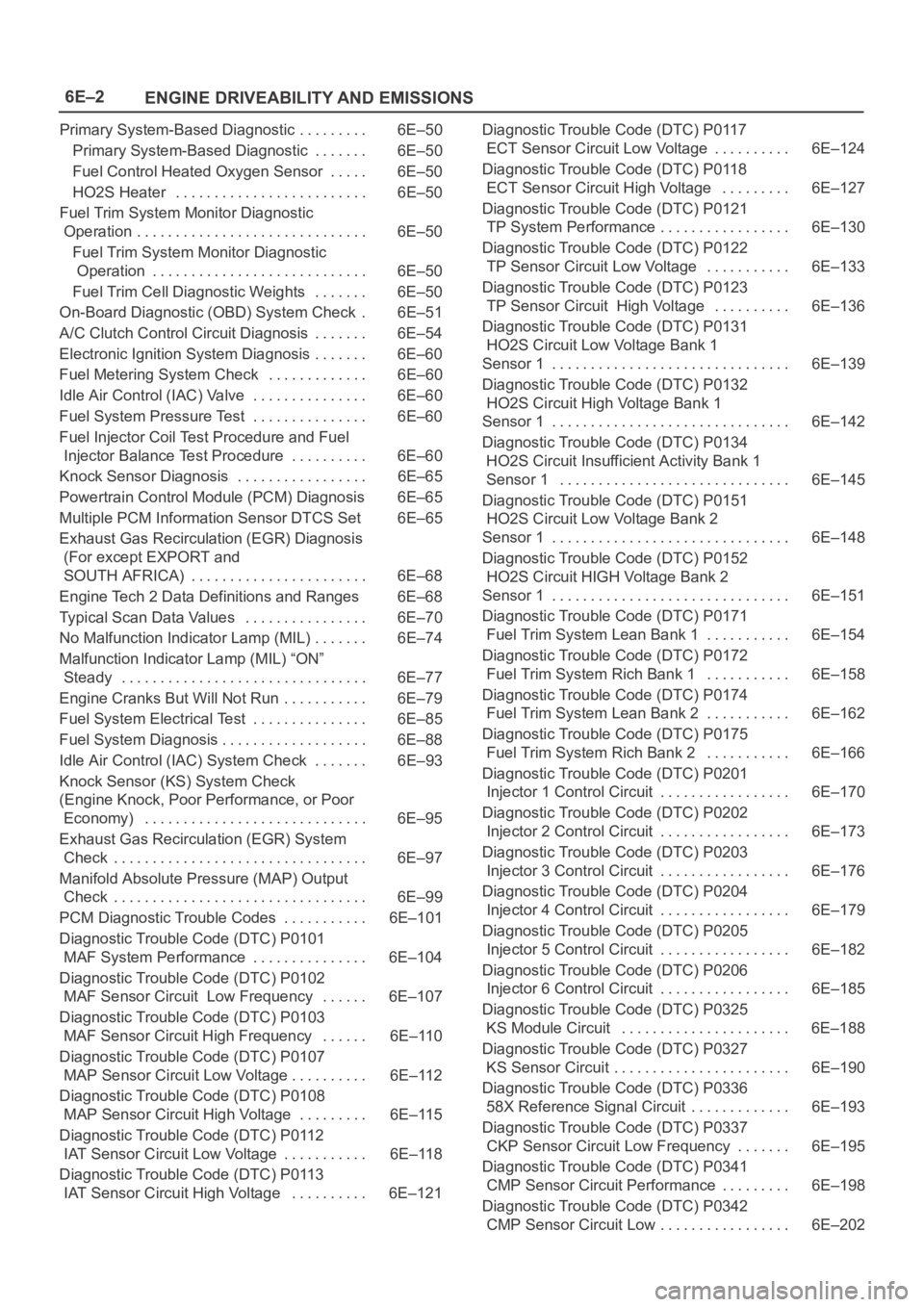
Primary System-Based Diagnostic 6E–50. . . . . . . . .
Primary System-Based Diagnostic 6E–50. . . . . . .
Fuel Control Heated Oxygen Sensor 6E–50. . . . .
HO2S Heater 6E–50. . . . . . . . . . . . . . . . . . . . . . . . .
Fuel Trim System Monitor Diagnostic
Operation 6E–50. . . . . . . . . . . . . . . . . . . . . . . . . . . . . .
Fuel Trim System Monitor Diagnostic
Operation 6E–50. . . . . . . . . . . . . . . . . . . . . . . . . . . .
Fuel Trim Cell Diagnostic Weights 6E–50. . . . . . .
On-Board Diagnostic (OBD) System Check 6E–51.
A/C Clutch Control Circuit Diagnosis 6E–54. . . . . . .
Electronic Ignition System Diagnosis 6E–60. . . . . . .
Fuel Metering System Check 6E–60. . . . . . . . . . . . .
Idle Air Control (IAC) Valve 6E–60. . . . . . . . . . . . . . .
Fuel System Pressure Test 6E–60. . . . . . . . . . . . . . .
Fuel Injector Coil Test Procedure and Fuel
Injector Balance Test Procedure 6E–60. . . . . . . . . .
Knock Sensor Diagnosis 6E–65. . . . . . . . . . . . . . . . .
Powertrain Control Module (PCM) Diagnosis 6E–65
Multiple PCM Information Sensor DTCS Set 6E–65
Exhaust Gas Recirculation (EGR) Diagnosis
(For except EXPORT and
SOUTH AFRICA) 6E–68. . . . . . . . . . . . . . . . . . . . . . .
Engine Tech 2 Data Definitions and Ranges 6E–68
Typical Scan Data Values 6E–70. . . . . . . . . . . . . . . .
No Malfunction Indicator Lamp (MIL) 6E–74. . . . . . .
Malfunction Indicator Lamp (MIL) “ON”
Steady 6E–77. . . . . . . . . . . . . . . . . . . . . . . . . . . . . . . .
Engine Cranks But Will Not Run 6E–79. . . . . . . . . . .
Fuel System Electrical Test 6E–85. . . . . . . . . . . . . . .
Fuel System Diagnosis 6E–88. . . . . . . . . . . . . . . . . . .
Idle Air Control (IAC) System Check 6E–93. . . . . . .
Knock Sensor (KS) System Check
(Engine Knock, Poor Performance, or Poor
Economy) 6E–95. . . . . . . . . . . . . . . . . . . . . . . . . . . . .
Exhaust Gas Recirculation (EGR) System
Check 6E–97. . . . . . . . . . . . . . . . . . . . . . . . . . . . . . . . .
Manifold Absolute Pressure (MAP) Output
Check 6E–99. . . . . . . . . . . . . . . . . . . . . . . . . . . . . . . . .
PCM Diagnostic Trouble Codes 6E–101. . . . . . . . . . .
Diagnostic Trouble Code (DTC) P0101
MAF System Performance 6E–104. . . . . . . . . . . . . . .
Diagnostic Trouble Code (DTC) P0102
MAF Sensor Circuit Low Frequency 6E–107. . . . . .
Diagnostic Trouble Code (DTC) P0103
MAF Sensor Circuit High Frequency 6E–110. . . . . .
Diagnostic Trouble Code (DTC) P0107
MAP Sensor Circuit Low Voltage 6E–112. . . . . . . . . .
Diagnostic Trouble Code (DTC) P0108
MAP Sensor Circuit High Voltage 6E–115. . . . . . . . .
Diagnostic Trouble Code (DTC) P0112
IAT Sensor Circuit Low Voltage 6E–118. . . . . . . . . . .
Diagnostic Trouble Code (DTC) P0113
IAT Sensor Circuit High Voltage 6E–121. . . . . . . . . . Diagnostic Trouble Code (DTC) P0117
ECT Sensor Circuit Low Voltage 6E–124. . . . . . . . . .
Diagnostic Trouble Code (DTC) P0118
ECT Sensor Circuit High Voltage 6E–127. . . . . . . . .
Diagnostic Trouble Code (DTC) P0121
TP System Performance 6E–130. . . . . . . . . . . . . . . . .
Diagnostic Trouble Code (DTC) P0122
TP Sensor Circuit Low Voltage 6E–133. . . . . . . . . . .
Diagnostic Trouble Code (DTC) P0123
TP Sensor Circuit High Voltage 6E–136. . . . . . . . . .
Diagnostic Trouble Code (DTC) P0131
HO2S Circuit Low Voltage Bank 1
Sensor 1 6E–139. . . . . . . . . . . . . . . . . . . . . . . . . . . . . . .
Diagnostic Trouble Code (DTC) P0132
HO2S Circuit High Voltage Bank 1
Sensor 1 6E–142. . . . . . . . . . . . . . . . . . . . . . . . . . . . . . .
Diagnostic Trouble Code (DTC) P0134
HO2S Circuit Insufficient Activity Bank 1
Sensor 1 6E–145. . . . . . . . . . . . . . . . . . . . . . . . . . . . . .
Diagnostic Trouble Code (DTC) P0151
HO2S Circuit Low Voltage Bank 2
Sensor 1 6E–148. . . . . . . . . . . . . . . . . . . . . . . . . . . . . . .
Diagnostic Trouble Code (DTC) P0152
HO2S Circuit HIGH Voltage Bank 2
Sensor 1 6E–151. . . . . . . . . . . . . . . . . . . . . . . . . . . . . . .
Diagnostic Trouble Code (DTC) P0171
Fuel Trim System Lean Bank 1 6E–154. . . . . . . . . . .
Diagnostic Trouble Code (DTC) P0172
Fuel Trim System Rich Bank 1 6E–158. . . . . . . . . . .
Diagnostic Trouble Code (DTC) P0174
Fuel Trim System Lean Bank 2 6E–162. . . . . . . . . . .
Diagnostic Trouble Code (DTC) P0175
Fuel Trim System Rich Bank 2 6E–166. . . . . . . . . . .
Diagnostic Trouble Code (DTC) P0201
Injector 1 Control Circuit 6E–170. . . . . . . . . . . . . . . . .
Diagnostic Trouble Code (DTC) P0202
Injector 2 Control Circuit 6E–173. . . . . . . . . . . . . . . . .
Diagnostic Trouble Code (DTC) P0203
Injector 3 Control Circuit 6E–176. . . . . . . . . . . . . . . . .
Diagnostic Trouble Code (DTC) P0204
Injector 4 Control Circuit 6E–179. . . . . . . . . . . . . . . . .
Diagnostic Trouble Code (DTC) P0205
Injector 5 Control Circuit 6E–182. . . . . . . . . . . . . . . . .
Diagnostic Trouble Code (DTC) P0206
Injector 6 Control Circuit 6E–185. . . . . . . . . . . . . . . . .
Diagnostic Trouble Code (DTC) P0325
KS Module Circuit 6E–188. . . . . . . . . . . . . . . . . . . . . .
Diagnostic Trouble Code (DTC) P0327
KS Sensor Circuit 6E–190. . . . . . . . . . . . . . . . . . . . . . .
Diagnostic Trouble Code (DTC) P0336
58X Reference Signal Circuit 6E–193. . . . . . . . . . . . .
Diagnostic Trouble Code (DTC) P0337
CKP Sensor Circuit Low Frequency 6E–195. . . . . . .
Diagnostic Trouble Code (DTC) P0341
CMP Sensor Circuit Performance 6E–198. . . . . . . . .
Diagnostic Trouble Code (DTC) P0342
CMP Sensor Circuit Low 6E–202. . . . . . . . . . . . . . . . .
Page 4697 of 6000
6E–40
ENGINE DRIVEABILITY AND EMISSIONS
Common OBD Terms
Diagnostic
When used as a noun, the word diagnostic refers to any
on-board test run by the vehicle’s Diagnostic
Management System. A diagnostic is simply a test run on
a system or component to determine if the system or
component is operating according to specification. There
are many diagnostics, shown in the following list:
Oxygen sensors
Oxygen sensor heaters
EGR
Catalyst monitoring
Enable Criteria
The term “enable criteria” is engineering language for the
conditions necessary for a given diagnostic test to run.
Each diagnostic has a specific list of conditions which
must be met before the diagnostic will run. “Enable
criteria” is another way of saying “conditions required”.
The enable criteria for each diagnostic is listed on the first
page of the DTC description under the heading
“Conditions for Setting the DTC”. Enable criteria varies
with each diagnostic, and typically includes, but is not
limited to the following items:
engine speed
vehicle speed
ECT
MAF/MAP
barometric pressure
IAT
TP
fuel trim
TCC enabled
A/C on
Tr i p
Technically, a trip is a key on-run-key off cycle in which all
the enable criteria for a given diagnostic are met, allowing
the diagnostic to run. Unfortunately, this concept is not
quite that simple. A trip is official when all the enable
criteria for a given diagnostic are met. But because the
enable criteria vary from one diagnostic to another, the
definition of trip varies as well. Some diagnostic are run
when the vehicle is at operating temperature, some when
the vehicle first start up; some require that the vehicle be
cruising at a steady highway speed, some run only when
the vehicle is idle; some diagnostics function with the
TCC disables. Some run only immediately following a
cold engine start-up.
A trip then, is defined as a key on-run-key off cycle in
which the vehicle was operated in such a way as to satisfy
the enables criteria for a given diagnostic, and this
diagnostic will consider this cycle to be one trip. However,
another diagnostic with a different set of enable criteria
(which were not met) during this driving event, would not
consider it a trip. No trip will occur for that particular
diagnostic until the vehicle is driven in such a way as to
meet all the enable criteria.
The Diagnostic Executive
The Diagnostic Executive is a unique segment of
software which is designed to coordinate and prioritize
the diagnostic procedures as well as define the protocol
for recording and displaying their results. The main
responsibilities of the Diagnostic Executive are listed as
following:
Commanding the MIL (“Check Engine” lamp) on and
off
DTC logging and clearing
Freeze Frame data for the first emission related DTC
recorded
Non-emission related Service Lamp (future)
Operating conditions Failure Records buffer, (the
number of records will vary)
Current status information on each diagnostic
The Diagnostic Executive records DTCs and turns on the
MIL when emission-related faults occur. It can also turn
off the MIL if the conditions cease which caused the DTC
to set.
Diagnostic Information
The diagnostic charts and functional checks are designed
to locate a faulty circuit or component through a process
of logical decisions. The charts are prepared with the
requirement that the vehicle functioned correctly at the
time of assembly and that there are not multiple faults
present.
There is a continuous self-diagnosis on certain control
functions. This diagnostic capability is complemented by
the diagnostic procedures contained in this manual. The
language of communicating the source of the malfunction
is a system of diagnostic trouble codes. When a
malfunction is detected by the control module, a
diagnostic trouble code is set and the Malfunction
Indicator Lamp (MIL) (“Check Engine” lamp) is
illuminated.
Malfunction Indicator Lamp (MIL)
The Malfunction Indicator Lamp (MIL) looks the same as
the MIL you are already familiar with (“Check Engine”
lamp). However, OBD requires that the it illuminate under
a strict set of guide lines.
Basically, the MIL is turned on when the PCM detects a
DTC that will impact the vehicle emissions.
The MIL is under the control of the Diagnostic Executive.
The MIL will be turned on if an emissions-related
diagnostic test indicates a malfunction has occurred. It
will stay on until the system or component passes the
same test, for three consecutive trips, with no
emissionsrelated faults.
Extinguishing the MIL
When the MIL is on, the Diagnostic Executive will turn off
the MIL after
three consecutive trips that a “test passed”
has been reported for the diagnostic test that originally
caused the MIL to illuminate.
Although the MIL has been turned off, the DTC will remain
in the PCM memory (both Freeze Frame and Failure
Records) until
forty(40) warm-up cycles after no faults
have been completed.
Page 4707 of 6000
6E–50
ENGINE DRIVEABILITY AND EMISSIONS
Primary System-Based Diagnostic
Primary System-Based Diagnostic
There are primary system-based diagnostics which
evaluate system operation and its effect on vehicle
emissions. The primary system-based diagnostics are
listed below with a brief description of the diagnostic
function:
Oxygen Sensor Diagnosis
The fuel control heated oxygen sensors (Bank 1 HO2S 1
and Bank 2 HO2S 1) are diagnosed for the following
conditions:
Inactive signal (output steady at bias voltage – approx.
450 mV)
Signal fixed high
Signal fixed low
If the oxygen sensor pigtail wiring, connector or terminal
are damaged, the entire oxygen sensor assembly must
be replaced. DO NOT attempt to repair the wiring,
connector or terminals. In order for the sensor to function
properly, it must have clean reference air provided to it.
This clean air reference is obtained by way of the oxygen
sensor wire(s). Any attempt to repair the wires, connector
or terminals could result in the obstruction of the
reference air and degrade oxygen sensor performance.
Refer to
On-Vehicle Service, Heated Oxygen Sensors.
Fuel Control Heated Oxygen Sensor
The main function of the fuel control heated oxygen
sensors is to provide the control module with exhaust
stream oxygen content information to allow proper fueling
and maintain emissions within mandated levels. After it
reaches operating temperature, the sensor will generate
a voltage, inversely proportional to the amount of oxygen
present in the exhaust gases. The control module uses
the signal voltage from the fuel control heated oxygen
sensors while in closed loop to adjust fuel injector pulse
width. While in closed loop, the PCM can adjust fuel
delivery to maintain an air/fuel ratio which allows the best
combination of emission control and driveability.
HO2S Heater
Heated oxygen sensors are used to minimize the amount
of time required for closed loop fuel control to begin
operation and to allow accurate catalyst monitoring. The
oxygen sensor heater greatly decreases the amount of
time required for fuel control sensors (Bank 1 HO2S 1 and
Bank2 HO2S 1) to become active. Oxygen sensor
heaters are required to maintain a sufficiently high
temperature which allows accurate exhaust oxygen
content readings further away from the engine.
Fuel Trim System Monitor Diagnostic
Operation
Fuel Trim System Monitor Diagnostic
Operation
This system monitors the averages of short-term and
long-term fuel trim values. If these fuel trim values stay at
their limits for a calibrated period of time, a malfunction is
indicated. The fuel trim diagnostic compares the
averages of short-term fuel trim values and long-term fuel
trim values to rich and lean thresholds. If either value is
within the thresholds, a pass is recorded. If both values
are outside their thresholds, a rich or lean DTC will be
recorded.
The fuel trim system diagnostic also conducts an intrusive
test. This test determines if a rich condition is being
caused by excessive fuel vapor from the EVAP canister.
In order to meet OBD requirements, the control module
uses weighted fuel trim cells to determine the need to set
a fuel trim DTC. A fuel trim DTC can only be set if fuel trim
counts in the weighted fuel trim cells exceed
specifications. This means that the vehicle could have a
fuel trim problem which is causing a problem under
certain conditions (i.e., engine idle high due to a small
vacuum leak or rough idle due to a large vacuum leak)
while it operates fine at other times. No fuel trim DTC
would set (although an engine idle speed DTC or HO2S
DTC may set). Use a Tech 2 to observe fuel trim counts
while the problem is occurring.
A fuel trim DTC may be triggered by a number of vehicle
faults. Make use of all information available (other DTCs
stored, rich or lean condition, etc.) when diagnosing a fuel
trim fault.
Fuel Trim Cell Diagnostic Weights
N o f u e l t r i m D T C w i l l s e t r e g a r d l e s s o f t h e f u e l t r i m c o u n t s
in cell 0 unless the fuel trim counts in the weighted cells
are also outside specifications. This means that the
vehicle could have a fuel trim problem which is causing a
problem under certain conditions (i.e. engine idle high due
to a small vacuum leak or rough due to a large vacuum
leak) while it operates fine at other times. No fuel trim
DTC would set (although an engine idle speed DTC or
HO2S DTC may set). Use a Tech 2 to observe fuel trim
counts while the problem is occurring.
Page 4712 of 6000
6E–55 ENGINE DRIVEABILITY AND EMISSIONS
Damaged harness–Inspect the wiring harness for
damage. If the harness appears to OK, observe the
A/C clutch while moving connectors and wiring
harnesses related to the A/C. A sudden clutch
malfunction will indicate the source of the intermittent
fault.
A/C Clutch Diagnosis
This chart should be used for diagnosing the electrical
p o r t i o n o f t h e A / C c o m p r e s s o r c l u t c h c i r c u i t . A Te c h 2 w i l l
be used in diagnosing the system. The Tech 2 has the
ability to read the A/C request input to the PCM. The Tech
2 can display when the PCM has commanded the A/C
clutch “ON.” The Tech 2 should have the ability to
override the A/C request signal and energize the A/C
compressor relay.
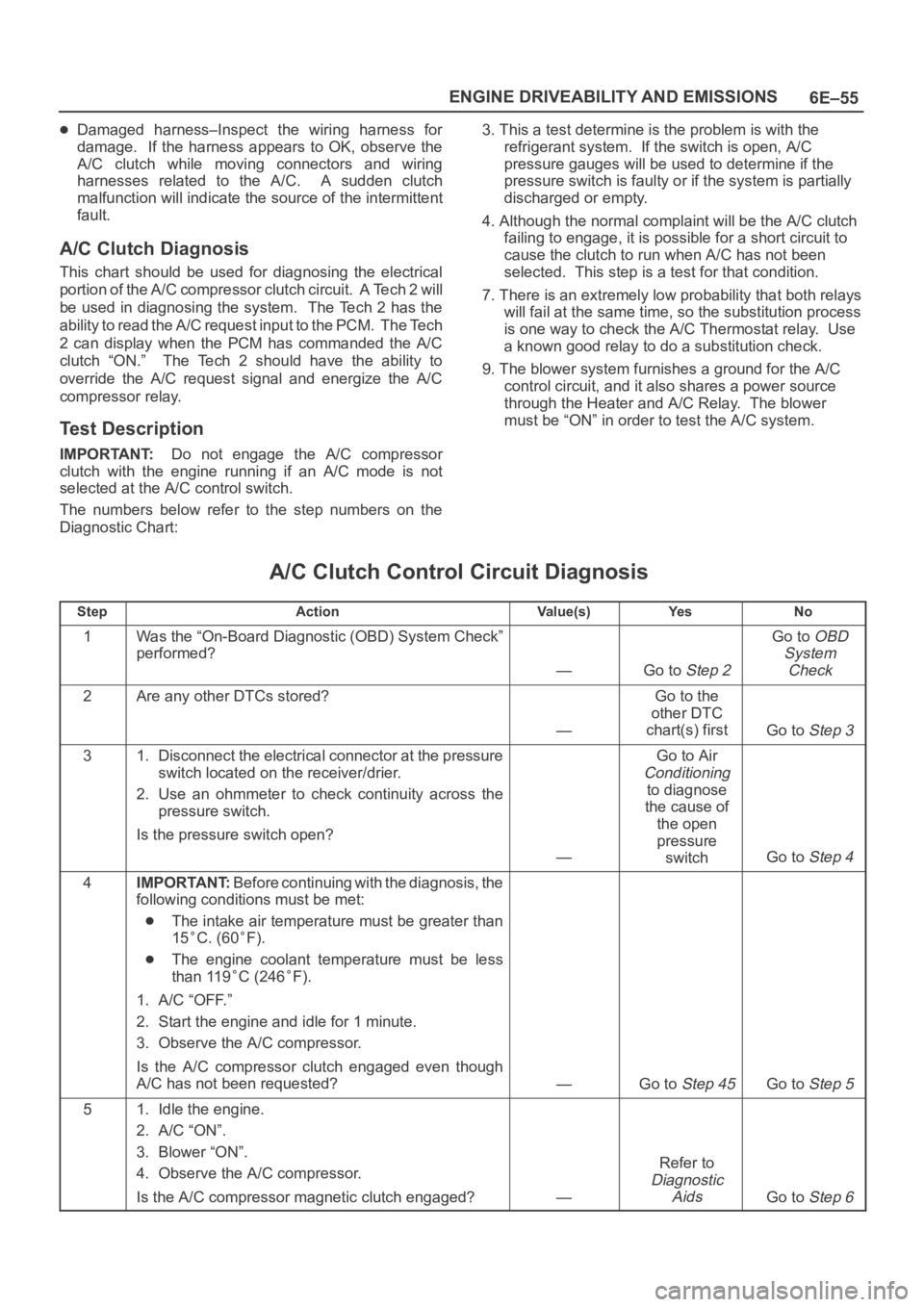
Test Description
IMPORTANT:Do not engage the A/C compressor
clutch with the engine running if an A/C mode is not
selected at the A/C control switch.
The numbers below refer to the step numbers on the
Diagnostic Chart:3. This a test determine is the problem is with the
refrigerant system. If the switch is open, A/C
pressure gauges will be used to determine if the
pressure switch is faulty or if the system is partially
discharged or empty.
4. Although the normal complaint will be the A/C clutch
failing to engage, it is possible for a short circuit to
cause the clutch to run when A/C has not been
selected. This step is a test for that condition.
7. There is an extremely low probability that both relays
will fail at the same time, so the substitution process
is one way to check the A/C Thermostat relay. Use
a known good relay to do a substitution check.
9. The blower system furnishes a ground for the A/C
control circuit, and it also shares a power source
through the Heater and A/C Relay. The blower
must be “ON” in order to test the A/C system.
A/C Clutch Control Circuit Diagnosis
StepActionVa l u e ( s )Ye sNo
1Was the “On-Board Diagnostic (OBD) System Check”
performed?
—Go to Step 2
Go to OBD
System
Check
2Are any other DTCs stored?
—
Go to the
other DTC
chart(s) first
Go to Step 3
31. Disconnect the electrical connector at the pressure
switch located on the receiver/drier.
2. Use an ohmmeter to check continuity across the
pressure switch.
Is the pressure switch open?
—
Go to Air
Conditioning
to diagnose
the cause of
the open
pressure
switch
Go to Step 4
4IMPORTANT:Before continuing with the diagnosis, the
following conditions must be met:
The intake air temperature must be greater than
15
C. (60F).
The engine coolant temperature must be less
than 119
C (246F).
1. A/C “OFF.”
2. Start the engine and idle for 1 minute.
3. Observe the A/C compressor.
Is the A/C compressor clutch engaged even though
A/C has not been requested?
—Go to Step 45Go to Step 5
51. Idle the engine.
2. A/C “ON”.
3. Blower “ON”.
4. Observe the A/C compressor.
Is the A/C compressor magnetic clutch engaged?
—
Refer to
Diagnostic
Aids
Go to Step 6
Page 4726 of 6000
6E–69 ENGINE DRIVEABILITY AND EMISSIONS
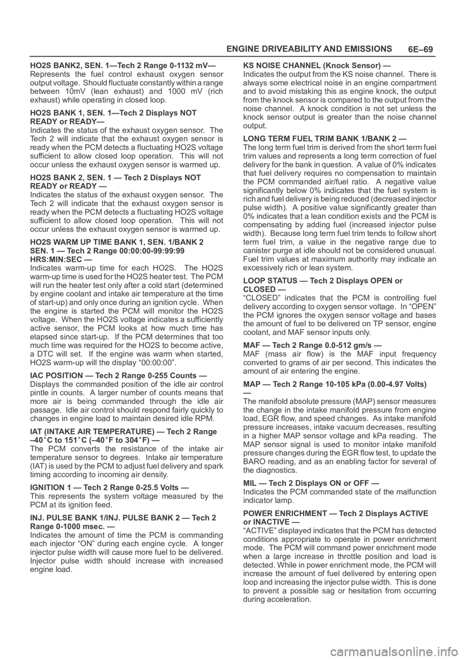
HO2S BANK2, SEN. 1—Tech 2 Range 0-1132 mV—
Represents the fuel control exhaust oxygen sensor
output voltage. Should fluctuate constantly within a range
between 10mV (lean exhaust) and 1000 mV (rich
exhaust) while operating in closed loop.
HO2S BANK 1, SEN. 1—Tech 2 Displays NOT
READY or READY—
Indicates the status of the exhaust oxygen sensor. The
Tech 2 will indicate that the exhaust oxygen sensor is
ready when the PCM detects a fluctuating HO2S voltage
sufficient to allow closed loop operation. This will not
occur unless the exhaust oxygen sensor is warmed up.
HO2S BANK 2, SEN. 1 — Tech 2 Displays NOT
READY or READY —
Indicates the status of the exhaust oxygen sensor. The
Tech 2 will indicate that the exhaust oxygen sensor is
ready when the PCM detects a fluctuating HO2S voltage
sufficient to allow closed loop operation. This will not
occur unless the exhaust oxygen sensor is warmed up.
HO2S WARM UP TIME BANK 1, SEN. 1/BANK 2
SEN. 1 — Tech 2 Range 00:00:00-99:99:99
HRS:MIN:SEC —
Indicates warm-up time for each HO2S. The HO2S
warm-up time is used for the HO2S heater test. The PCM
will run the heater test only after a cold start (determined
by engine coolant and intake air temperature at the time
of start-up) and only once during an ignition cycle. When
the engine is started the PCM will monitor the HO2S
voltage. When the HO2S voltage indicates a sufficiently
active sensor, the PCM looks at how much time has
elapsed since start-up. If the PCM determines that too
much time was required for the HO2S to become active,
a DTC will set. If the engine was warm when started,
HO2S warm-up will the display “00:00:00”.
IAC POSITION — Tech 2 Range 0-255 Counts —
Displays the commanded position of the idle air control
pintle in counts. A larger number of counts means that
more air is being commanded through the idle air
passage. Idle air control should respond fairly quickly to
changes in engine load to maintain desired idle RPM.
IAT (INTAKE AIR TEMPERATURE) — Tech 2 Range
–40
C to 151C (–40F to 304F) —
The PCM converts the resistance of the intake air
temperature sensor to degrees. Intake air temperature
(IAT) is used by the PCM to adjust fuel delivery and spark
timing according to incoming air density.
IGNITION 1 — Tech 2 Range 0-25.5 Volts —
This represents the system voltage measured by the
PCM at its ignition feed.
INJ. PULSE BANK 1/INJ. PULSE BANK 2 — Tech 2
Range 0-1000 msec. —
Indicates the amount of time the PCM is commanding
each injector “ON” during each engine cycle. A longer
injector pulse width will cause more fuel to be delivered.
Injector pulse width should increase with increased
engine load.KS NOISE CHANNEL (Knock Sensor) —
Indicates the output from the KS noise channel. There is
always some electrical noise in an engine compartment
and to avoid mistaking this as engine knock, the output
from the knock sensor is compared to the output from the
noise channel. A knock condition is not set unless the
knock sensor output is greater than the noise channel
output.
LONG TERM FUEL TRIM BANK 1/BANK 2 —
The long term fuel trim is derived from the short term fuel
trim values and represents a long term correction of fuel
delivery for the bank in question. A value of 0% indicates
that fuel delivery requires no compensation to maintain
the PCM commanded air/fuel ratio. A negative value
significantly below 0% indicates that the fuel system is
rich and fuel delivery is being reduced (decreased injector
pulse width). A positive value significantly greater than
0% indicates that a lean condition exists and the PCM is
compensating by adding fuel (increased injector pulse
width). Because long term fuel trim tends to follow short
term fuel trim, a value in the negative range due to
canister purge at idle should not be considered unusual.
Fuel trim values at maximum authority may indicate an
excessively rich or lean system.
LOOP STATUS — Tech 2 Displays OPEN or
CLOSED —
“CLOSED” indicates that the PCM is controlling fuel
delivery according to oxygen sensor voltage. In “OPEN”
the PCM ignores the oxygen sensor voltage and bases
the amount of fuel to be delivered on TP sensor, engine
coolant, and MAF sensor inputs only.
MAF — Tech 2 Range 0.0-512 gm/s —
MAF (mass air flow) is the MAF input frequency
converted to grams of air per second. This indicates the
amount of air entering the engine.
MAP — Tech 2 Range 10-105 kPa (0.00-4.97 Volts)
—
The manifold absolute pressure (MAP) sensor measures
the change in the intake manifold pressure from engine
load, EGR flow, and speed changes. As intake manifold
pressure increases, intake vacuum decreases, resulting
in a higher MAP sensor voltage and kPa reading. The
MAP sensor signal is used to monitor intake manifold
pressure changes during the EGR flow test, to update the
BARO reading, and as an enabling factor for several of
the diagnostics.
MIL — Tech 2 Displays ON or OFF —
Indicates the PCM commanded state of the malfunction
indicator lamp.
POWER ENRICHMENT — Tech 2 Displays ACTIVE
or INACTIVE —
“ACTIVE” displayed indicates that the PCM has detected
conditions appropriate to operate in power enrichment
mode. The PCM will command power enrichment mode
when a large increase in throttle position and load is
detected. While in power enrichment mode, the PCM will
increase the amount of fuel delivered by entering open
loop and increasing the injector pulse width. This is done
to prevent a possible sag or hesitation from occurring
during acceleration.
Page 4797 of 6000
6E–140
ENGINE DRIVEABILITY AND EMISSIONS
HO2S, causing the system to appear lean. Check for
exhaust leaks that may cause a false lean condition to
be indicated.
MAF sensor – The system can go lean if the MAF
sensor signal indicates an engine airfiow
measurement that is not correct. Disconnect the MAF
sensor to see if the lean condition is corrected. If so,
replace the MAF sensor.
Fuel contamination – Water, even in small amounts,
can be delivered to the fuel injectors. The water can
cause a lean exhaust to be indicated. Excessive
alcohol in the fuel can also cause this condition. Refer
to
Fuel System Diagnosis for the procedure to check
for fuel contamination.
If none of the above conditions are present, replace the
affected HO2S.
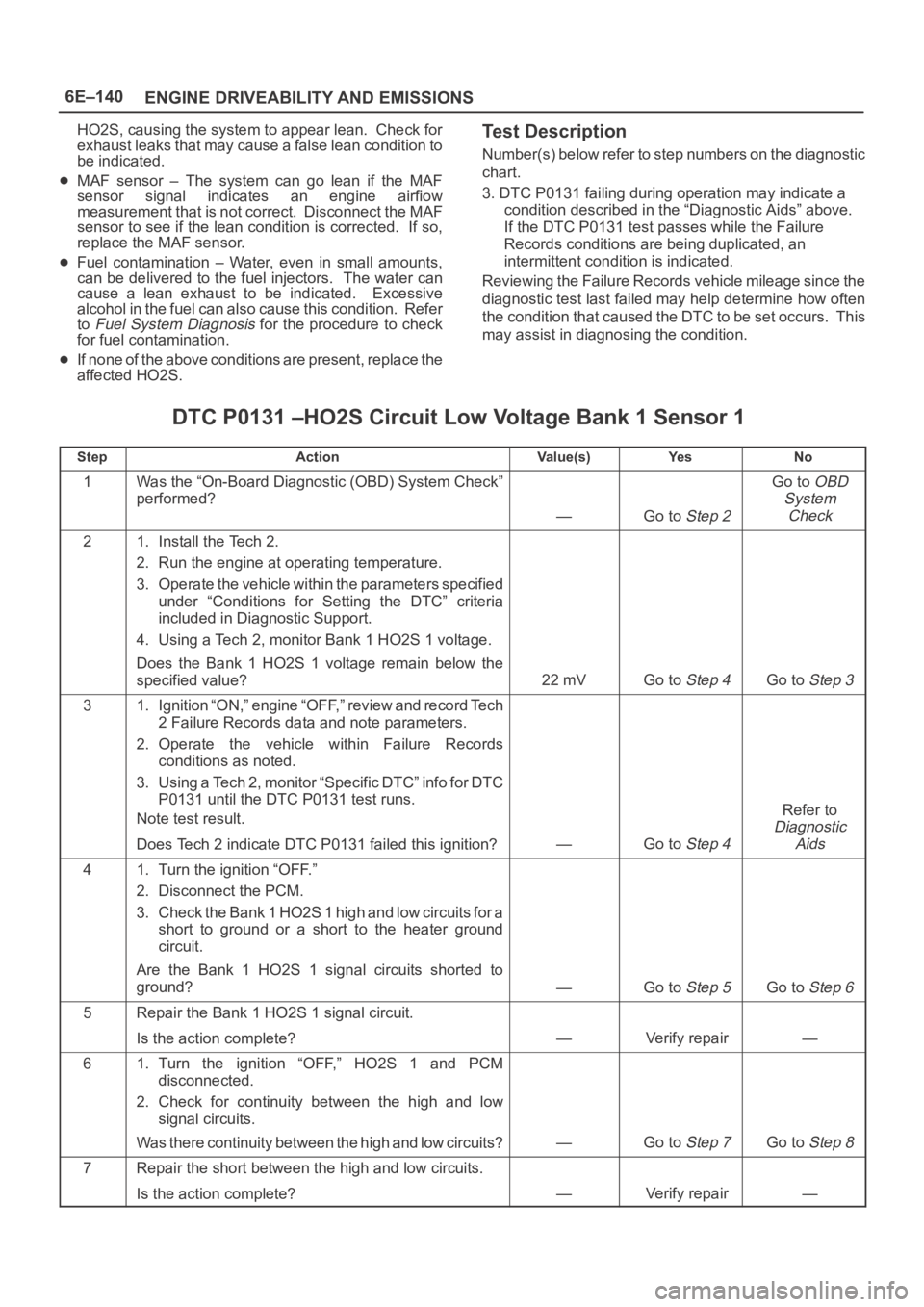
Test Description
Number(s) below refer to step numbers on the diagnostic
chart.
3. DTC P0131 failing during operation may indicate a
condition described in the “Diagnostic Aids” above.
If the DTC P0131 test passes while the Failure
Records conditions are being duplicated, an
intermittent condition is indicated.
Reviewing the Failure Records vehicle mileage since the
diagnostic test last failed may help determine how often
the condition that caused the DTC to be set occurs. This
may assist in diagnosing the condition.
DTC P0131 –HO2S Circuit Low Voltage Bank 1 Sensor 1
StepActionVa l u e ( s )Ye sNo
1Was the “On-Board Diagnostic (OBD) System Check”
performed?
—Go to Step 2
Go to OBD
System
Check
21. Install the Tech 2.
2. Run the engine at operating temperature.
3. Operate the vehicle within the parameters specified
under “Conditions for Setting the DTC” criteria
included in Diagnostic Support.
4. Using a Tech 2, monitor Bank 1 HO2S 1 voltage.
Does the Bank 1 HO2S 1 voltage remain below the
specified value?
22 mVGo to Step 4Go to Step 3
31. Ignition “ON,” engine “OFF,” review and record Tech
2 Failure Records data and note parameters.
2. Operate the vehicle within Failure Records
conditions as noted.
3. Using a Tech 2, monitor “Specific DTC” info for DTC
P0131 until the DTC P0131 test runs.
Note test result.
Does Tech 2 indicate DTC P0131 failed this ignition?
—Go to Step 4
Refer to
Diagnostic
Aids
41. Turn the ignition “OFF.”
2. Disconnect the PCM.
3. Check the Bank 1 HO2S 1 high and low circuits for a
short to ground or a short to the heater ground
circuit.
Are the Bank 1 HO2S 1 signal circuits shorted to
ground?
—Go to Step 5Go to Step 6
5Repair the Bank 1 HO2S 1 signal circuit.
Is the action complete?
—Verify repair—
61. Turn the ignition “OFF,” HO2S 1 and PCM
disconnected.
2. Check for continuity between the high and low
signal circuits.
Was there continuity between the high and low circuits?
—Go to Step 7Go to Step 8
7Repair the short between the high and low circuits.
Is the action complete?
—Verify repair—
Page 4802 of 6000
6E–145 ENGINE DRIVEABILITY AND EMISSIONS
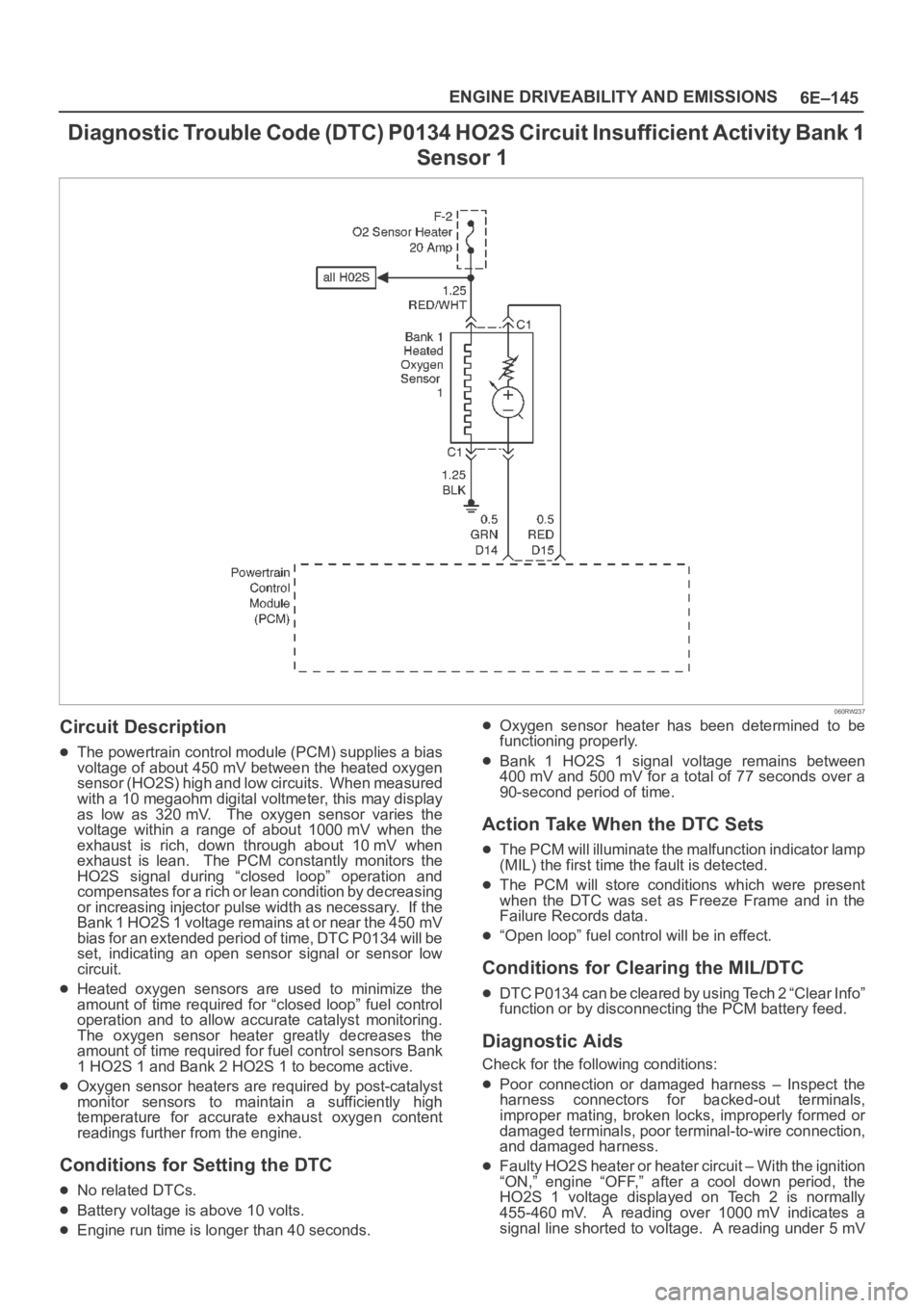
D i a g n o s t i c Tr o u b l e C o d e ( D T C ) P 0 1 3 4 H O 2 S C i r c u i t I n s u f f i c i e n t Activity Bank 1
Sensor 1
060RW237
Circuit Description
The powertrain control module (PCM) supplies a bias
voltage of about 450 mV between the heated oxygen
s e n s o r ( H O 2 S ) h i g h a n d l o w c i r c u i t s . W h e n m e a s u r e d
with a 10 megaohm digital voltmeter, this may display
as low as 320 mV. The oxygen sensor varies the
voltage within a range of about 1000 mV when the
exhaust is rich, down through about 10 mV when
exhaust is lean. The PCM constantly monitors the
HO2S signal during “closed loop” operation and
compensates for a rich or lean condition by decreasing
or increasing injector pulse width as necessary. If the
Bank 1 HO2S 1 voltage remains at or near the 450 mV
bias for an extended period of time, DTC P0134 will be
set, indicating an open sensor signal or sensor low
circuit.
Heated oxygen sensors are used to minimize the
amount of time required for “closed loop” fuel control
operation and to allow accurate catalyst monitoring.
The oxygen sensor heater greatly decreases the
amount of time required for fuel control sensors Bank
1 HO2S 1 and Bank 2 HO2S 1 to become active.
Oxygen sensor heaters are required by post-catalyst
monitor sensors to maintain a sufficiently high
temperature for accurate exhaust oxygen content
readings further from the engine.
Conditions for Setting the DTC
No related DTCs.
Battery voltage is above 10 volts.
Engine run time is longer than 40 seconds.
Oxygen sensor heater has been determined to be
functioning properly.
Bank 1 HO2S 1 signal voltage remains between
400 mV and 500 mV for a total of 77 seconds over a
90-second period of time.
Action Take When the DTC Sets
The PCM will illuminate the malfunction indicator lamp
(MIL) the first time the fault is detected.
The PCM will store conditions which were present
when the DTC was set as Freeze Frame and in the
Failure Records data.
“Open loop” fuel control will be in effect.
Conditions for Clearing the MIL/DTC
DTC P0134 can be cleared by using Tech 2 “Clear Info”
function or by disconnecting the PCM battery feed.
Diagnostic Aids
Check for the following conditions:
Poor connection or damaged harness – Inspect the
harness connectors for backed-out terminals,
improper mating, broken locks, improperly formed or
damaged terminals, poor terminal-to-wire connection,
and damaged harness.
Faulty HO2S heater or heater circuit – With the ignition
“ON,” engine “OFF,” after a cool down period, the
HO2S 1 voltage displayed on Tech 2 is normally
455-460 mV. A reading over 1000 mV indicates a
signal line shorted to voltage. A reading under 5 mV
Page 4803 of 6000
6E–146
ENGINE DRIVEABILITY AND EMISSIONS
indicates a signal line shorted to ground or signal lines
shorted together. Disconnect the HO2S and connect
a test light between the HO2S ignition feed and heater
ground circuits. If the test light does not light for 2
seconds when the ignition is turned on, repair the open
ignition feed or sensor ground circuit as necessary. If
the test light lights and the HO2S signal and low circuits
are OK, replace the HO2S.
Intermittent test – With the Ignition “ON,” monitor the
HO2S signal voltage while moving the wiring harness
and related connectors. If the fault is induced, the
HO2S signal voltage will change. This may help isolate
the location of the malfunction.
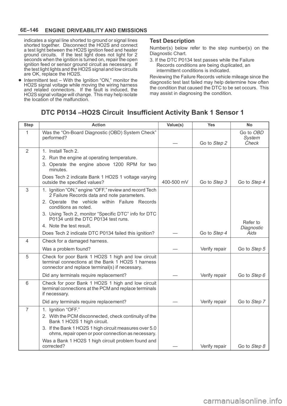
Test Description
Number(s) below refer to the step number(s) on the
Diagnostic Chart.
3. If the DTC P0134 test passes while the Failure
Records conditions are being duplicated, an
intermittent conditions is indicated.
Reviewing the Failure Records vehicle mileage since the
diagnostic test last failed may help determine how often
the condition that caused the DTC to be set occurs. This
may assist in diagnosing the condition.
DTC P0134 –HO2S Circuit Insufficient Activity Bank 1 Sensor 1
StepActionVa l u e ( s )Ye sNo
1Was the “On-Board Diagnostic (OBD) System Check”
performed?
—Go to Step 2
Go to OBD
System
Check
21. Install Tech 2.
2. Run the engine at operating temperature.
3. Operate the engine above 1200 RPM for two
minutes.
Does Tech 2 indicate Bank 1 HO2S 1 voltage varying
outside the specified values?
400-500 mVGo to Step 3Go to Step 4
31. Ignition “ON,” engine “OFF,” review and record Tech
2 Failure Records data and note parameters.
2. Operate the vehicle within Failure Records
conditions as noted.
3. Using Tech 2, monitor “Specific DTC” info for DTC
P0134 until the DTC P0134 test runs.
4. Note the test result.
Does Tech 2 indicate DTC P0134 failed this ignition?
—Go to Step 4
Refer to
Diagnostic
Aids
4Check for a damaged harness.
Was a problem found?
—Verify repairGo to Step 5
5Check for poor Bank 1 HO2S 1 high and low circuit
terminal connections at the Bank 1 HO2S 1 harness
connector and replace terminal(s) if necessary.
Did any terminals require replacement?
—Verify repairGo to Step 6
6Check for poor Bank 1 HO2S 1 high and low circuit
terminal connections at the PCM and replace terminals
if necessary.
Did any terminals require replacement?
—Verify repairGo to Step 7
71. Ignition “OFF.”
2. With the PCM disconnected, check continuity of the
Bank 1 HO2S 1 high circuit.
3. If the Bank 1 HO2S 1 high circuit measures over 5.0
ohms, repair open or poor connection as necessary.
Was a Bank 1 HO2S 1 high circuit problem found and
corrected?
—Verify repairGo to Step 8