1998 OPEL FRONTERA heater
[x] Cancel search: heaterPage 3089 of 6000
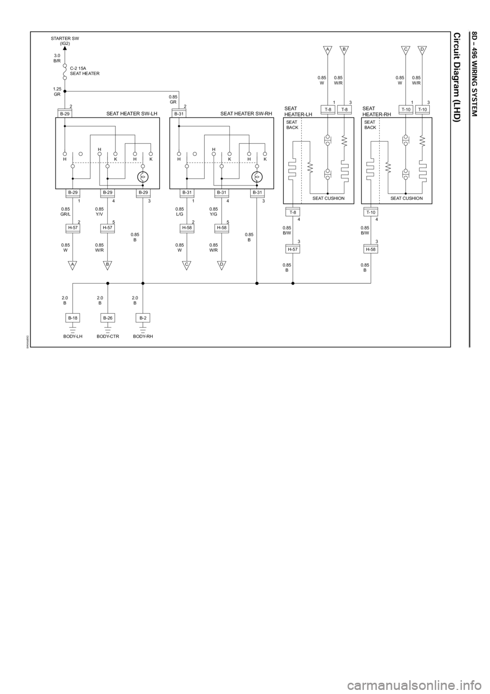
D08RW948
H HH
K K
B-29 STARTER SW
(IG2)
1.25
GR
0.85
GR/L
0.85
W0.85
Y/V
0.85
W/R0.85
B
2.0
B0.85
GR 3.0
B/R
C-2 15A
SEAT HEATERSEAT HEATER SW-LH2
3
B-29
4B-29
1B-29
5
H-57 2H-57
BA
H HH
K K
B-31
0.85
L/G
0.85
W0.85
Y/G
0.85
W/R0.85
B0.85
B/W
0.85
BSEAT HEATER SW-RHSEAT
HEATER-LH2
3
B-31
SEAT CUSHION SEAT
BACK
4B-31
1B-31
5
H-58 2H-58
DC
B-2
BODY-RH
2.0
B
B-26
BODY-CTR
2.0
B
B-18
BODY-LH
T-8
4
H-5733
T- 8 1T-8 0.85
W0.85
W/R
AB
0.85
B/W
0.85
B
SEAT
HEATER-RH
SEAT CUSHION SEAT
BACK
T-1 0
4
H-5833
T- 1 0 1T- 1 0 0.85
W0.85
W/R
CD
Page 3248 of 6000
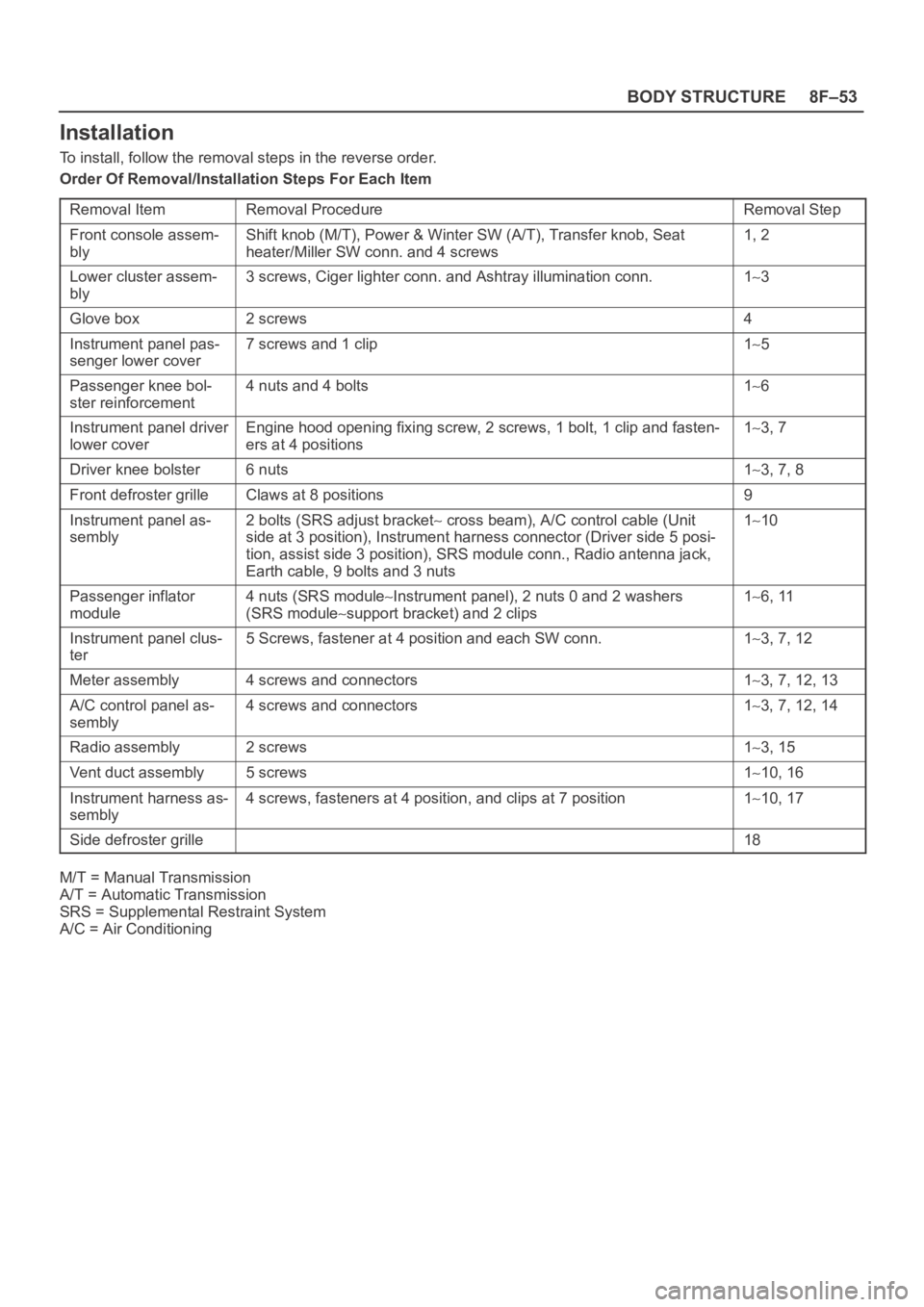
8F–53 BODY STRUCTURE
Installation
To install, follow the removal steps in the reverse order.
Order Of Removal/Installation Steps For Each Item
Removal Item
Removal ProcedureRemoval Step
Front console assem-
blyShift knob (M/T), Power & Winter SW (A/T), Transfer knob, Seat
heater/Miller SW conn. and 4 screws1, 2
Lower cluster assem-
bly3 screws, Ciger lighter conn. and Ashtray illumination conn.13
Glove box2 screws4
Instrument panel pas-
senger lower cover7 screws and 1 clip15
Passenger knee bol-
ster reinforcement4 nuts and 4 bolts16
Instrument panel driver
lower coverEngine hood opening fixing screw, 2 screws, 1 bolt, 1 clip and fasten-
ers at 4 positions13, 7
Driver knee bolster6 nuts13, 7, 8
Front defroster grilleClaws at 8 positions9
Instrument panel as-
sembly2 bolts (SRS adjust bracket cross beam), A/C control cable (Unit
side at 3 position), Instrument harness connector (Driver side 5 posi-
tion, assist side 3 position), SRS module conn., Radio antenna jack,
Earth cable, 9 bolts and 3 nuts110
Passenger inflator
module4 nuts (SRS moduleInstrument panel), 2 nuts 0 and 2 washers
(SRS module
support bracket) and 2 clips
16, 11
Instrument panel clus-
ter5 Screws, fastener at 4 position and each SW conn.13, 7, 12
Meter assembly4 screws and connectors13, 7, 12, 13
A/C control panel as-
sembly4 screws and connectors13, 7, 12, 14
Radio assembly2 screws13, 15
Vent duct assembly5 screws110, 16
Instrument harness as-
sembly4 screws, fasteners at 4 position, and clips at 7 position110, 17
Side defroster grille18
M/T = Manual Transmission
A/T = Automatic Transmission
SRS = Supplemental Restraint System
A/C = Air Conditioning
Page 3313 of 6000
SEATS8G–1
BODY AND ACCESSORIES
SEATS
CONTENTS
Service Precaution 8G–1. . . . . . . . . . . . . . . . . . . . . .
Front Seat Assembly 8G–2. . . . . . . . . . . . . . . . . . . .
Front Seat Assembly and Associated
Parts 8G–2. . . . . . . . . . . . . . . . . . . . . . . . . . . . . . . .
Removal 8G–2. . . . . . . . . . . . . . . . . . . . . . . . . . . . .
Installation 8G–3. . . . . . . . . . . . . . . . . . . . . . . . . . . .
Disassembled View (Long Wheel Base) 8G–3. .
Disassembly 8G–4. . . . . . . . . . . . . . . . . . . . . . . . . .
Reassembly 8G–5. . . . . . . . . . . . . . . . . . . . . . . . . .
Disassembled View (Short Wheel Base) 8G–6. .
Disassembly 8G–6. . . . . . . . . . . . . . . . . . . . . . . . . .
Reassembly 8G–8. . . . . . . . . . . . . . . . . . . . . . . . . .
Power Seat Assembly 8G–9. . . . . . . . . . . . . . . . . . .
General Description 8G–9. . . . . . . . . . . . . . . . . . . . . .
Disassembled View 8G–9. . . . . . . . . . . . . . . . . . . .
Disassembly 8G–10. . . . . . . . . . . . . . . . . . . . . . . . . .
Reassembly 8G–12. . . . . . . . . . . . . . . . . . . . . . . . . .
Power Seat Switch 8G–12. . . . . . . . . . . . . . . . . . . . . .
Removal 8G–12. . . . . . . . . . . . . . . . . . . . . . . . . . . . .
Installation 8G–12. . . . . . . . . . . . . . . . . . . . . . . . . . . .
Front Tilt Motor / Rear Tilt Motor /
Slide Motor / Recliner Motor 8G–13. . . . . . . . . . . . . .
Parts Location 8G–13. . . . . . . . . . . . . . . . . . . . . . . .
Removal and Installation 8G–13. . . . . . . . . . . . . . .
Seat Heater System 8G–14. . . . . . . . . . . . . . . . . . . . .
General Description 8G–14. . . . . . . . . . . . . . . . . . . . . .
Seat Heater Switch Removal and
Installation 8G–14. . . . . . . . . . . . . . . . . . . . . . . . . . . Heat Unit Parts Location 8G–14. . . . . . . . . . . . . . . .
Heat Unit Removal and Installation 8G–14. . . . . .
Rear Seat Assembly 8G–15. . . . . . . . . . . . . . . . . . . . .
Rear Seat Assembly and Associated Parts 8G–15
Removal 8G–15. . . . . . . . . . . . . . . . . . . . . . . . . . . . .
Installation 8G–15. . . . . . . . . . . . . . . . . . . . . . . . . . . .
Disassembled View (Split Type) 8G–16. . . . . . . . .
Disassembly (Split Type) 8G–17. . . . . . . . . . . . . . .
Reassembly (Split Type) 8G–18. . . . . . . . . . . . . . . .
Disassembled View (Short Wheel Base) 8G–19. .
Disassembly 8G–19. . . . . . . . . . . . . . . . . . . . . . . . . .
Reassembly 8G–20. . . . . . . . . . . . . . . . . . . . . . . . . .
Disassembled View (Bench Type) 8G–21. . . . . . .
Disassembly (Bench Type) 8G–22. . . . . . . . . . . . .
Reassembly (Bench Type) 8G–23. . . . . . . . . . . . . .
Third Seat Assembly 8G–23. . . . . . . . . . . . . . . . . . . . .
Parts Location 8G–23. . . . . . . . . . . . . . . . . . . . . . . .
Removal 8G–23. . . . . . . . . . . . . . . . . . . . . . . . . . . . .
Installation 8G–24. . . . . . . . . . . . . . . . . . . . . . . . . . . .
Disassembled View 8G–24. . . . . . . . . . . . . . . . . . . .
Disassembly 8G–25. . . . . . . . . . . . . . . . . . . . . . . . . .
Reassembly 8G–25. . . . . . . . . . . . . . . . . . . . . . . . . .
Rear Seat Foot Rest 8G–25. . . . . . . . . . . . . . . . . . . . .
Rear Seat Foot Rest and Associated Parts 8G–25
Removal 8G–26. . . . . . . . . . . . . . . . . . . . . . . . . . . . .
Installation 8G–26
. . . . . . . . . . . . . . . . . . . . . . . . . . . .
Main Data and Specifications 8G–26. . . . . . . . . . . . .
Service Precaution
WARNING: IF SO EQUIPPED WITH A
SUPPLEMENTAL RESTRAINT SYSTEM (SRS),
REFER TO THE SRS COMPONENT AND WIRING
LOCATION VIEW IN ORDER TO DETERMINE
WHETHER YOU ARE PERFORMING SERVICE ON OR
NEAR THE SRS COMPONENTS OR THE SRS
WIRING. WHEN YOU ARE PERFORMING SERVICE
ON OR NEAR THE SRS COMPONENTS OR THE SRS
WIRING, REFER TO THE SRS SERVICE
INFORMATION. FAILURE TO FOLLOW WARNINGS
COULD RESULT IN POSSIBLE AIR BAG
DEPLOYMENT, PERSONAL INJURY, OR
OTHERWISE UNNEEDED SRS SYSTEM REPAIRS.CAUTION: Always use the correct fastener in the
proper location. When you replace a fastener, use
ONLY the exact part number for that application.
ISUZU will call out those fasteners that require a
replacement after removal. ISUZU will also call out
the fasteners that require thread lockers or thread
sealant. UNLESS OTHERWISE SPECIFIED, do not
use supplemental coatings (Paints, greases, or other
corrosion inhibitors) on threaded fasteners or
fastener joint interfaces. Generally, such coatings
adversely affect the fastener torque and the joint
clamping force, and may damage the fastener. When
you install fasteners, use the correct tightening
sequence and specifications. Following these
instructions can help you avoid damage to parts and
systems.
Page 3315 of 6000
SEATS8G–3
Installation
To install, follow the removal steps in the reverse order,
noting the following points:1. Tighten the front seat assembly fixing bolts to the
specified torque.
Torque: 40 Nꞏm (4.1 kgꞏm/30 lb ft)
2. Install the longest bolt to the rear inner side fixing
location, if this model is equipped with power seats.
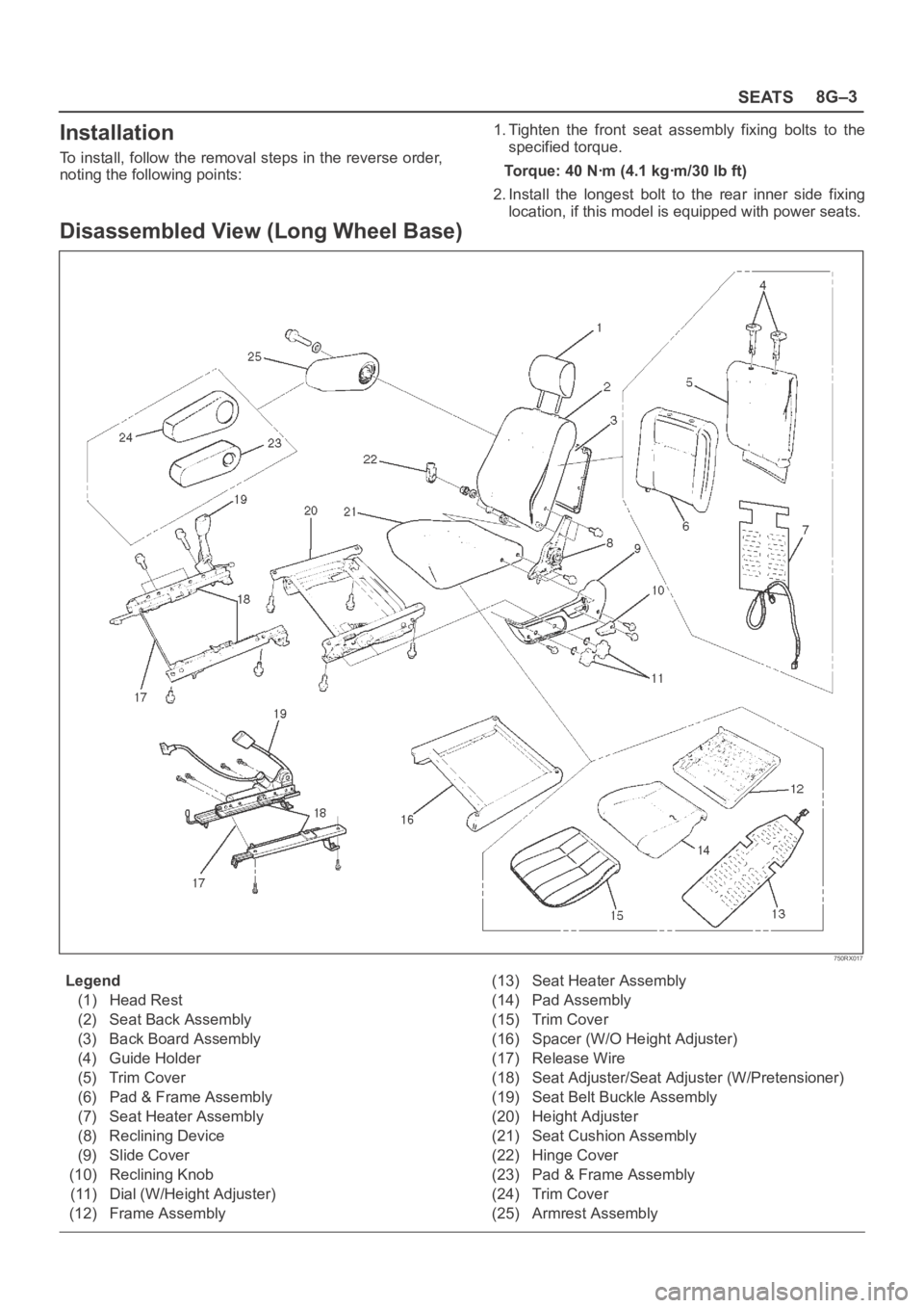
Disassembled View (Long Wheel Base)
750RX017
Legend
(1) Head Rest
(2) Seat Back Assembly
(3) Back Board Assembly
(4) Guide Holder
(5) Trim Cover
(6) Pad & Frame Assembly
(7) Seat Heater Assembly
(8) Reclining Device
(9) Slide Cover
(10) Reclining Knob
(11) Dial (W/Height Adjuster)
(12) Frame Assembly(13) Seat Heater Assembly
(14) Pad Assembly
(15) Trim Cover
(16) Spacer (W/O Height Adjuster)
(17) Release Wire
(18) Seat Adjuster/Seat Adjuster (W/Pretensioner)
(19) Seat Belt Buckle Assembly
(20) Height Adjuster
(21) Seat Cushion Assembly
(22) Hinge Cover
(23) Pad & Frame Assembly
(24) Trim Cover
(25) Armrest Assembly
Page 3317 of 6000
SEATS8G–5
11. Remove the seat back assembly.
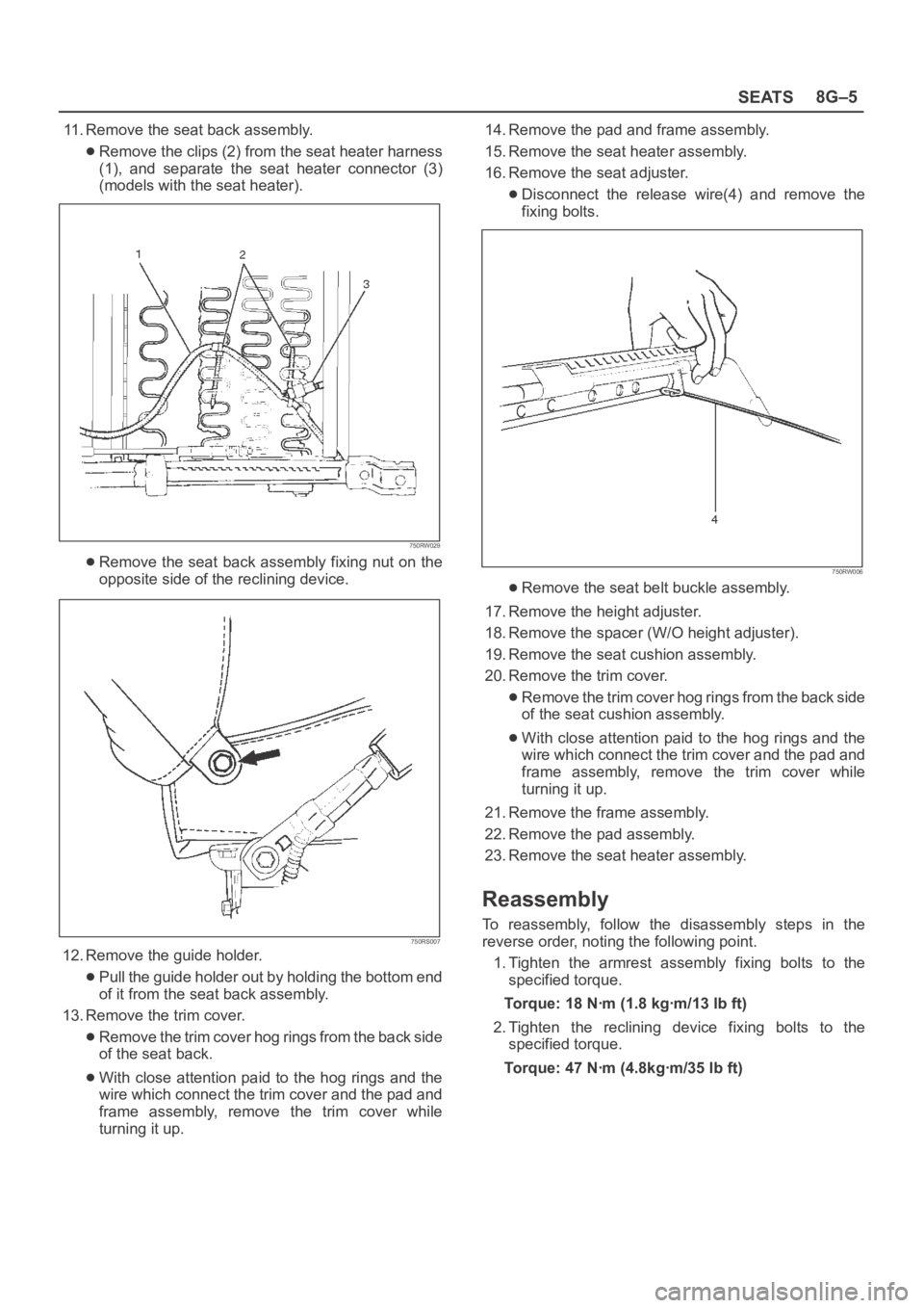
Remove the clips (2) from the seat heater harness
(1), and separate the seat heater connector (3)
(models with the seat heater).
750RW029
Remove the seat back assembly fixing nut on the
opposite side of the reclining device.
750RS007
12. Remove the guide holder.
Pull the guide holder out by holding the bottom end
of it from the seat back assembly.
13. Remove the trim cover.
Remove the trim cover hog rings from the back side
of the seat back.
With close attention paid to the hog rings and the
wire which connect the trim cover and the pad and
frame assembly, remove the trim cover while
turning it up.14. Remove the pad and frame assembly.
15. Remove the seat heater assembly.
16. Remove the seat adjuster.
Disconnect the release wire(4) and remove the
fixing bolts.
750RW006
Remove the seat belt buckle assembly.
17. Remove the height adjuster.
18. Remove the spacer (W/O height adjuster).
19. Remove the seat cushion assembly.
20. Remove the trim cover.
Remove the trim cover hog rings from the back side
of the seat cushion assembly.
With close attention paid to the hog rings and the
wire which connect the trim cover and the pad and
frame assembly, remove the trim cover while
turning it up.
21. Remove the frame assembly.
22. Remove the pad assembly.
23. Remove the seat heater assembly.
Reassembly
To reassembly, follow the disassembly steps in the
reverse order, noting the following point.
1. Tighten the armrest assembly fixing bolts to the
specified torque.
Torque: 18 Nꞏm (1.8 kgꞏm/13 lb ft)
2. Tighten the reclining device fixing bolts to the
specified torque.
Torque: 47 Nꞏm (4.8kgꞏm/35 lb ft)
Page 3322 of 6000
8G–10SEATS
(24) Seat Heater
(25) Frame Assembly
(26) Pad Assembly
(27) Trim Cover(28) Seat Heater
(29) Frame Assembly
(30) Head Rest
(31) Seat Back Assembly
Disassembly
1. Disconnect the battery ground cable.
2. Remove the head rest.
3. Remove the switch knob.
Pull the switch knob out.
4. Remove the outer cover cap.
5. Remove the outer cover fixing screws.
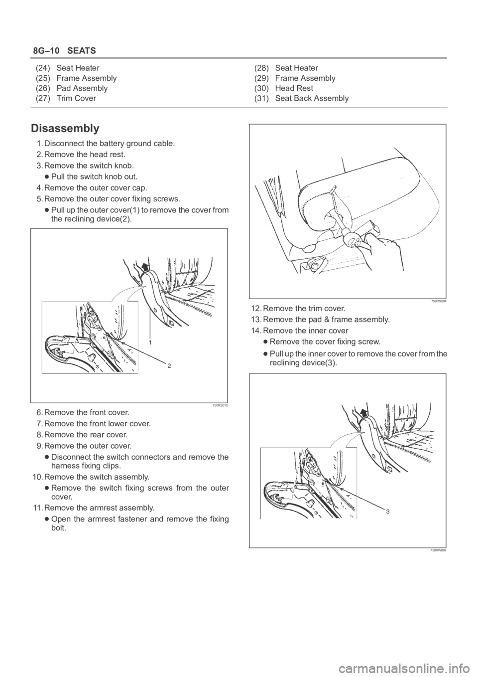
Pull up the outer cover(1) to remove the cover from
the reclining device(2).
750RS012
6. Remove the front cover.
7. Remove the front lower cover.
8. Remove the rear cover.
9. Remove the outer cover.
Disconnect the switch connectors and remove the
harness fixing clips.
10. Remove the switch assembly.
Remove the switch fixing screws from the outer
cover.
11. Remove the armrest assembly.
Open the armrest fastener and remove the fixing
bolt.
750RS004
12. Remove the trim cover.
13. Remove the pad & frame assembly.
14. Remove the inner cover
Remove the cover fixing screw.
Pull up the inner cover to remove the cover from the
reclining device(3).
750RW007
Page 3323 of 6000
SEATS8G–11
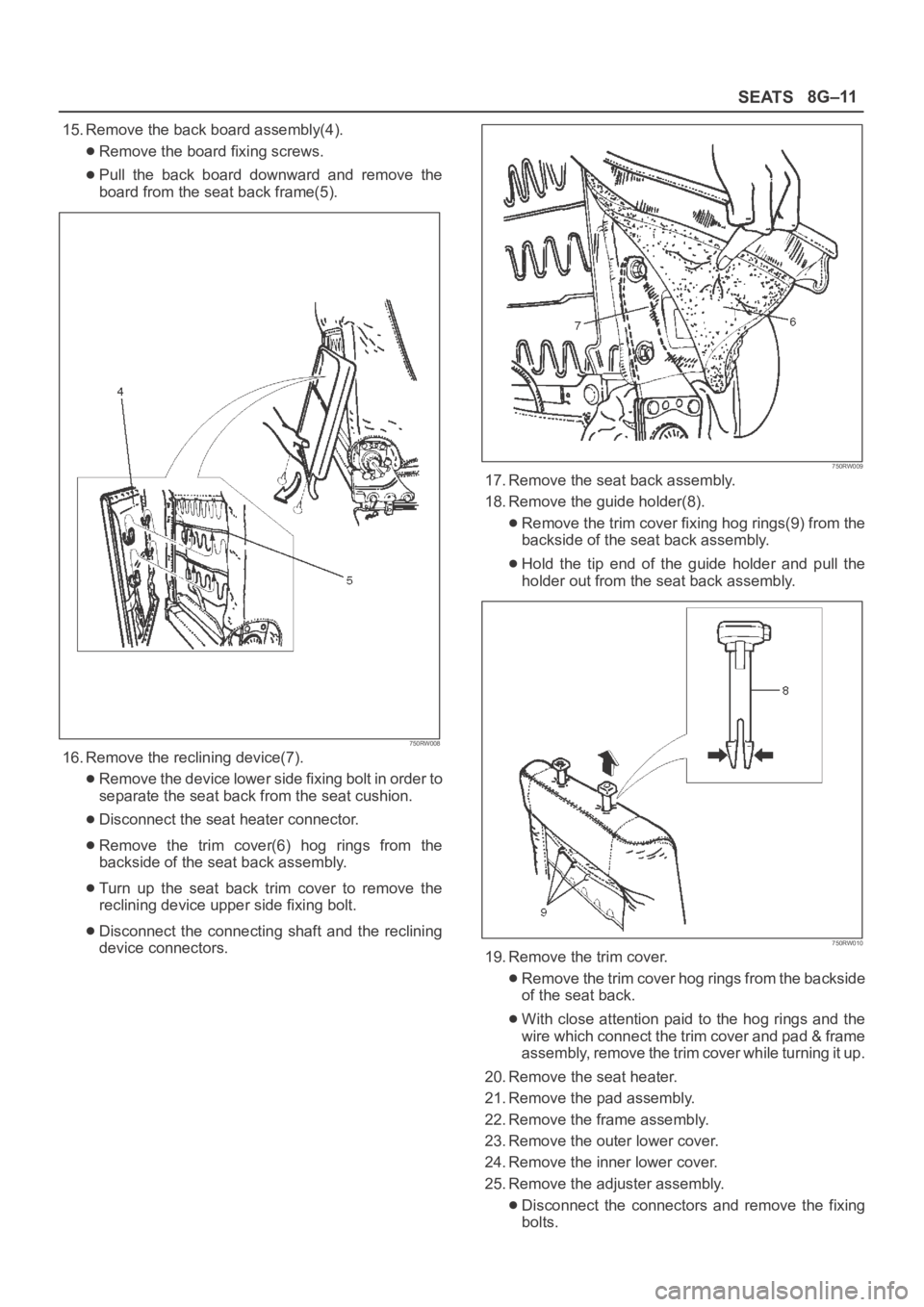
15. Remove the back board assembly(4).
Remove the board fixing screws.
Pull the back board downward and remove the
board from the seat back frame(5).
750RW008
16. Remove the reclining device(7).
Remove the device lower side fixing bolt in order to
separate the seat back from the seat cushion.
Disconnect the seat heater connector.
Remove the trim cover(6) hog rings from the
backside of the seat back assembly.
Turn up the seat back trim cover to remove the
reclining device upper side fixing bolt.
Disconnect the connecting shaft and the reclining
device connectors.
750RW009
17. Remove the seat back assembly.
18. Remove the guide holder(8).
Remove the trim cover fixing hog rings(9) from the
backside of the seat back assembly.
Hold the tip end of the guide holder and pull the
holder out from the seat back assembly.
750RW010
19. Remove the trim cover.
Remove the trim cover hog rings from the backside
of the seat back.
With close attention paid to the hog rings and the
wire which connect the trim cover and pad & frame
assembly, remove the trim cover while turning it up.
20. Remove the seat heater.
21. Remove the pad assembly.
22. Remove the frame assembly.
23. Remove the outer lower cover.
24. Remove the inner lower cover.
25. Remove the adjuster assembly.
Disconnect the connectors and remove the fixing
bolts.
Page 3324 of 6000
8G–12SEATS
Remove the power seat harness from the adjuster
assembly.
26. Remove the seat cushion assembly.
27. Remove the trim cover.
Remove the trim cover hog rings from the backside
of the seat cushion assembly.
With close attention paid to the hog rings and the
wire which connect the trim cover and the pad &
frame assembly, remove the trim cover while
turning it up.28. Remove the seat heater.
29. Remove the frame assembly.
30. Remove the pad assembly.
Reassembly
To reassemble, follow the disassembly steps in the
reverse order, noting the following point.
1. Tighten the fixing bolts to the specified torque.
Refer to the Torque Specifications in this section.
Power Seat Switch
Removal
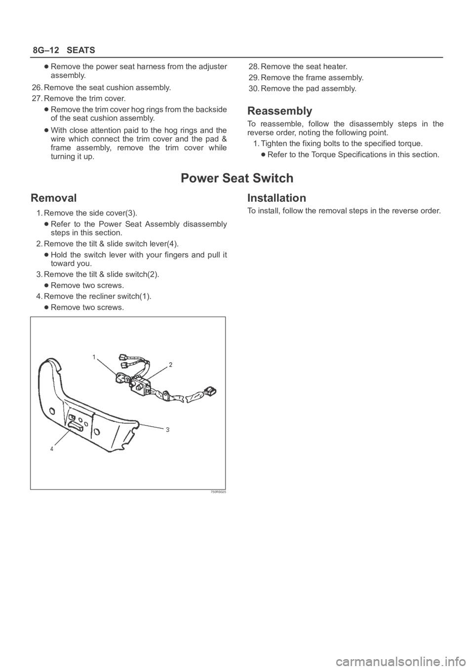
1. Remove the side cover(3).
Refer to the Power Seat Assembly disassembly
steps in this section.
2. Remove the tilt & slide switch lever(4).
Hold the switch lever with your fingers and pull it
toward you.
3. Remove the tilt & slide switch(2).
Remove two screws.
4. Remove the recliner switch(1).
Remove two screws.
750RS025
Installation
To install, follow the removal steps in the reverse order.