1998 OPEL FRONTERA heater
[x] Cancel search: heaterPage 4806 of 6000

6E–149 ENGINE DRIVEABILITY AND EMISSIONS
exhaust leaks that may cause a false lean condition to
be indicated.
MAF sensor –The system can go lean if the MAF
sensor signal indicates an engine airflow
measurement that is not correct. Disconnect the MAF
sensor to see if the lean condition is corrected. If so,
replace the MAF sensor.
Fuel contamination – Water, even in small amounts,
can be delivered to the fuel injectors. The water can
cause a lean exhaust to be indicated. Excessive
alcohol in the fuel can also cause this condition. Refer
to
Fuel System Diagnosis for the procedure to check
for fuel contamination.
If none of the above conditions are present, replace the
affected HO2S.
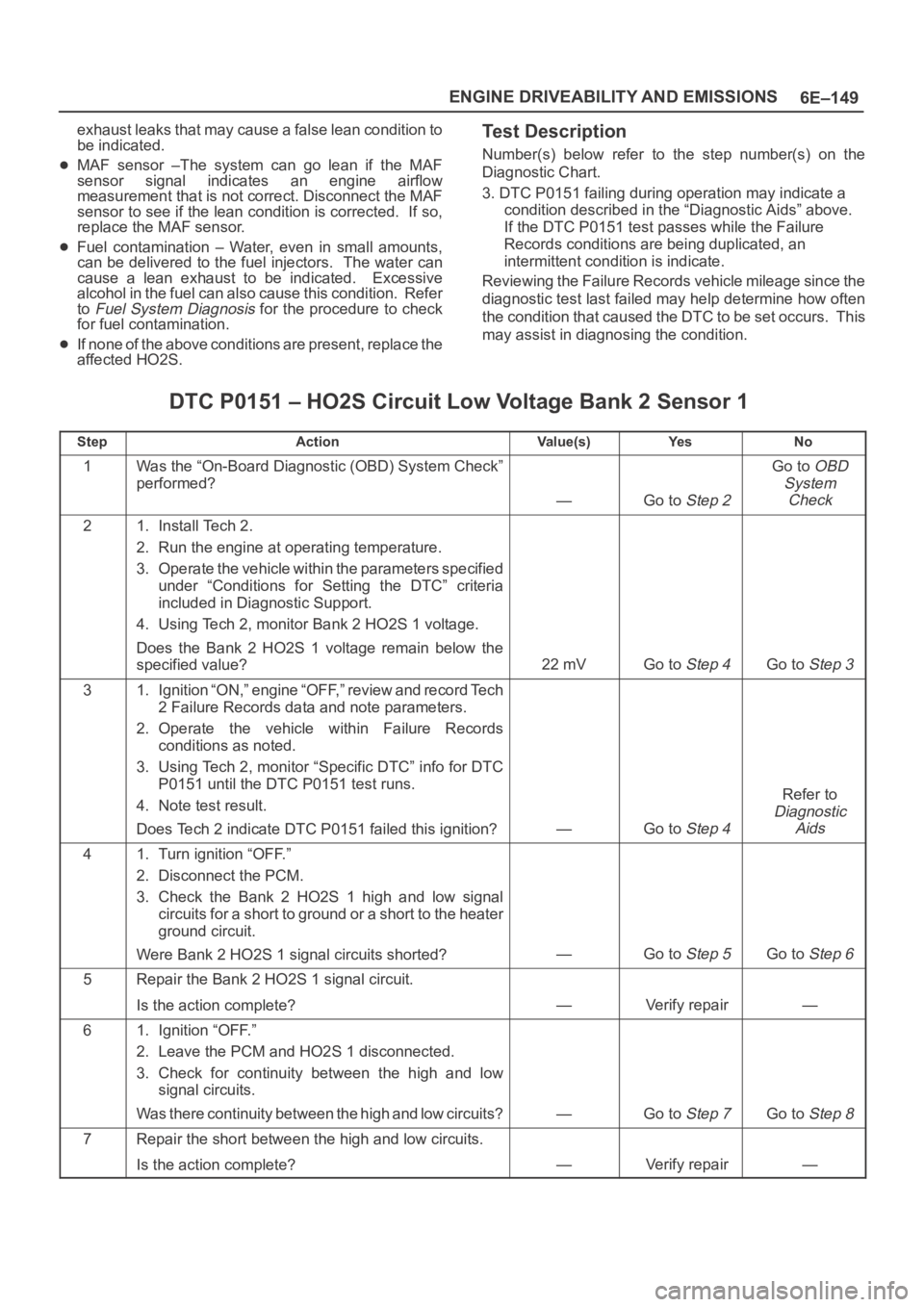
Test Description
Number(s) below refer to the step number(s) on the
Diagnostic Chart.
3. DTC P0151 failing during operation may indicate a
condition described in the “Diagnostic Aids” above.
If the DTC P0151 test passes while the Failure
Records conditions are being duplicated, an
intermittent condition is indicate.
Reviewing the Failure Records vehicle mileage since the
diagnostic test last failed may help determine how often
the condition that caused the DTC to be set occurs. This
may assist in diagnosing the condition.
DTC P0151 – HO2S Circuit Low Voltage Bank 2 Sensor 1
StepActionVa l u e ( s )Ye sNo
1Was the “On-Board Diagnostic (OBD) System Check”
performed?
—Go to Step 2
Go to OBD
System
Check
21. Install Tech 2.
2. Run the engine at operating temperature.
3. Operate the vehicle within the parameters specified
under “Conditions for Setting the DTC” criteria
included in Diagnostic Support.
4. Using Tech 2, monitor Bank 2 HO2S 1 voltage.
Does the Bank 2 HO2S 1 voltage remain below the
specified value?
22 mVGo to Step 4Go to Step 3
31. Ignition “ON,” engine “OFF,” review and record Tech
2 Failure Records data and note parameters.
2. Operate the vehicle within Failure Records
conditions as noted.
3. Using Tech 2, monitor “Specific DTC” info for DTC
P0151 until the DTC P0151 test runs.
4. Note test result.
Does Tech 2 indicate DTC P0151 failed this ignition?
—Go to Step 4
Refer to
Diagnostic
Aids
41. Turn ignition “OFF.”
2. Disconnect the PCM.
3. Check the Bank 2 HO2S 1 high and low signal
circuits for a short to ground or a short to the heater
ground circuit.
Were Bank 2 HO2S 1 signal circuits shorted?
—Go to Step 5Go to Step 6
5Repair the Bank 2 HO2S 1 signal circuit.
Is the action complete?
—Verify repair—
61. Ignition “OFF.”
2. Leave the PCM and HO2S 1 disconnected.
3. Check for continuity between the high and low
signal circuits.
Was there continuity between the high and low circuits?
—Go to Step 7Go to Step 8
7Repair the short between the high and low circuits.
Is the action complete?
—Verify repair—
Page 4898 of 6000

6E–241 ENGINE DRIVEABILITY AND EMISSIONS
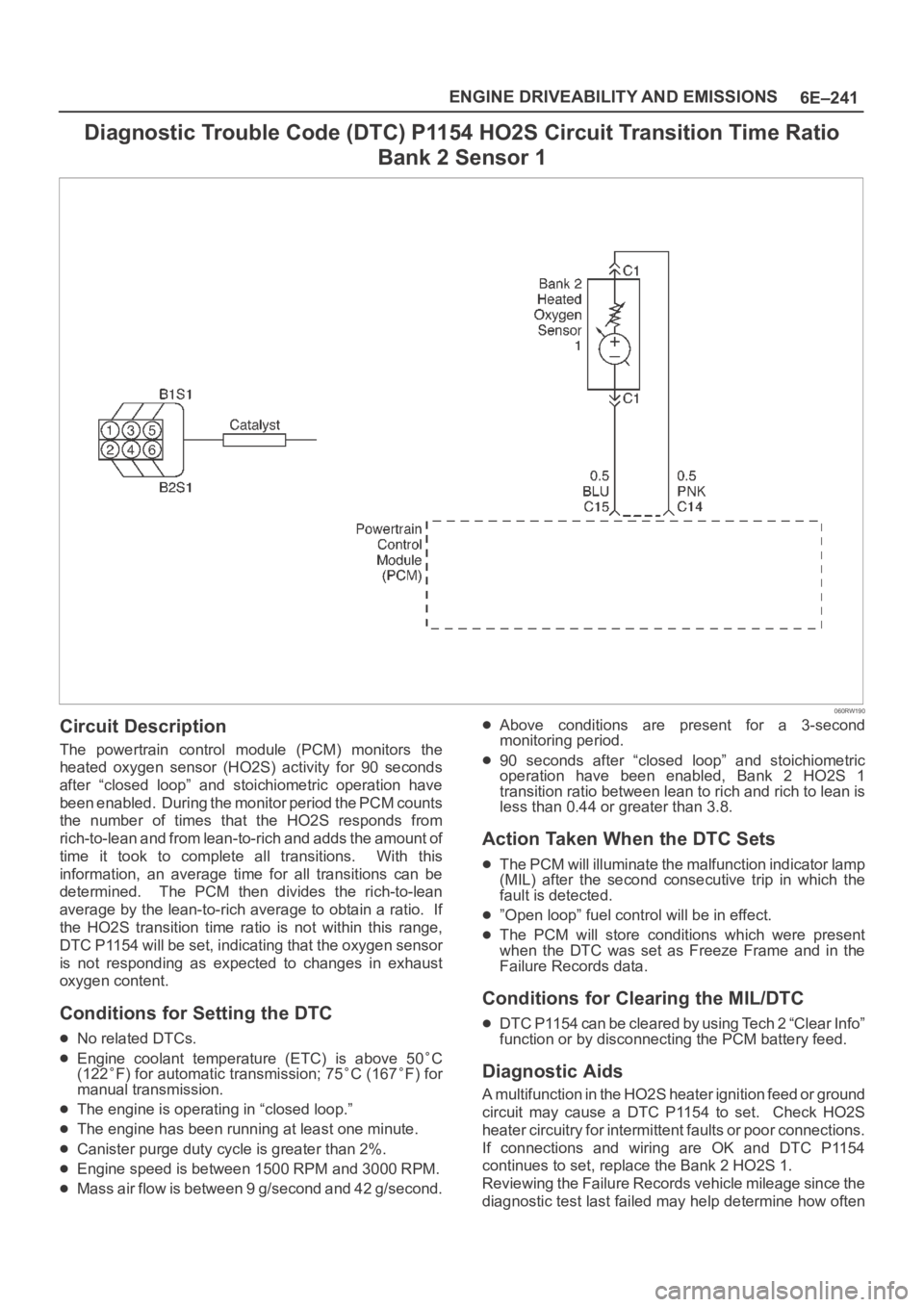
Diagnostic Trouble Code (DTC) P1154 HO2S Circuit Transition Time Ratio
Bank 2 Sensor 1
060RW190
Circuit Description
The powertrain control module (PCM) monitors the
heated oxygen sensor (HO2S) activity for 90 seconds
after “closed loop” and stoichiometric operation have
been enabled. During the monitor period the PCM counts
the number of times that the HO2S responds from
rich-to-lean and from lean-to-rich and adds the amount of
time it took to complete all transitions. With this
information, an average time for all transitions can be
determined. The PCM then divides the rich-to-lean
average by the lean-to-rich average to obtain a ratio. If
the HO2S transition time ratio is not within this range,
DTC P1154 will be set, indicating that the oxygen sensor
is not responding as expected to changes in exhaust
oxygen content.
Conditions for Setting the DTC
No related DTCs.
Engine coolant temperature (ETC) is above 50C
(122F) for automatic transmission; 75C (167F) for
manual transmission.
The engine is operating in “closed loop.”
The engine has been running at least one minute.
Canister purge duty cycle is greater than 2%.
Engine speed is between 1500 RPM and 3000 RPM.
Mass air flow is between 9 g/second and 42 g/second.
Above conditions are present for a 3-second
monitoring period.
90 seconds after “closed loop” and stoichiometric
operation have been enabled, Bank 2 HO2S 1
transition ratio between lean to rich and rich to lean is
less than 0.44 or greater than 3.8.
Action Taken When the DTC Sets
The PCM will illuminate the malfunction indicator lamp
(MIL) after the second consecutive trip in which the
fault is detected.
”Open loop” fuel control will be in effect.
The PCM will store conditions which were present
when the DTC was set as Freeze Frame and in the
Failure Records data.
Conditions for Clearing the MIL/DTC
DTC P1154 can be cleared by using Tech 2 “Clear Info”
function or by disconnecting the PCM battery feed.
Diagnostic Aids
A multifunction in the HO2S heater ignition feed or ground
circuit may cause a DTC P1154 to set. Check HO2S
heater circuitry for intermittent faults or poor connections.
If connections and wiring are OK and DTC P1154
continues to set, replace the Bank 2 HO2S 1.
Reviewing the Failure Records vehicle mileage since the
diagnostic test last failed may help determine how often
Page 4956 of 6000

6E–299 ENGINE DRIVEABILITY AND EMISSIONS
damage, therefore, it is important to use care when
handling and testing electronic components.
NOTE: To prevent possible Electrostatic Discharge
damage, follow these guidelines:
Do not touch the control module connector pins or
soldered components on the control module circuit
board.
Do not open the replacement part package until the
part is ready to be installed.
Before removing the part from the package, ground
the package to a known good ground on the vehicle.
If the part has been handled while sliding across the
seat, or while sitting down from a standing position, or
while walking a distance, touch a known good ground
before installing the part.
NOTE: To prevent internal PCM damage, the ignition
must be in the “OFF” position in order to disconnect or
reconnect power to the PCM (for example: battery cable,
PCM pigtail, PCM fuse, jumper cables, etc.).
IMPORTANT:When replacing the production PCM
with a service PCM, it is important to transfer the
broadcast code and production PCM number to the
service PCM label. This will allow positive identification of
PCM parts throughout the service life of the vehicle. Do
not record this information on the metal PCM cover.
IMPORTANT:The ignition should always be in the
“OFF” position in order to install or remove the PCM
connectors.
Service of the PCM should normally consist of either re-
placement of the PCM or EEPROM programming. If the
diagnostic procedures call for the PCM to be replaced,
the PCM should be checked first to ensure it is the correct
part. If it is, remove the faulty PCM and install the new
service PCM.
The service PCM EEPROM will not be programmed.
DTC P0601 indicates the check sum error.
Removal Procedure
1. Disconnect the negative battery cable.
2. Block the wheels.
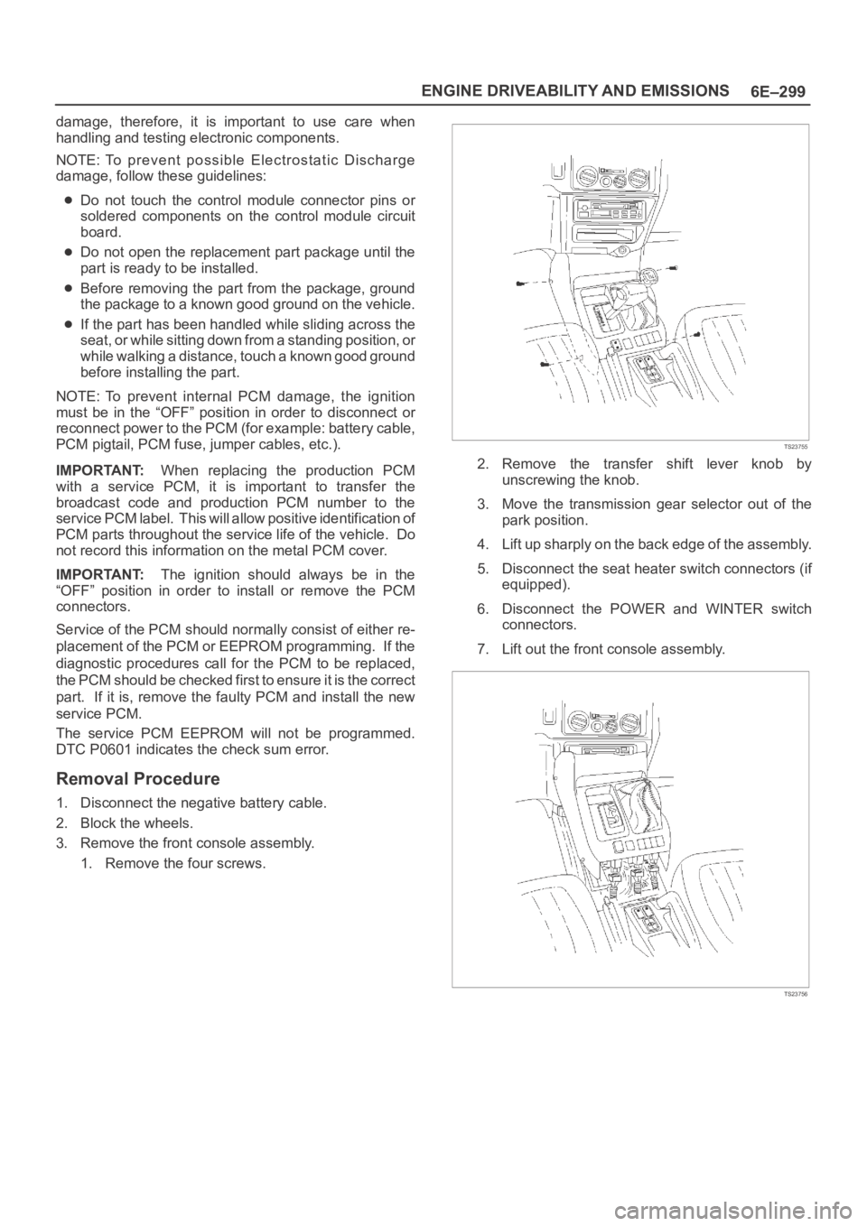
3. Remove the front console assembly.
1. Remove the four screws.
TS23755
2. Remove the transfer shift lever knob by
unscrewing the knob.
3. Move the transmission gear selector out of the
park position.
4. Lift up sharply on the back edge of the assembly.
5. Disconnect the seat heater switch connectors (if
equipped).
6. Disconnect the POWER and WINTER switch
connectors.
7. Lift out the front console assembly.
TS23756
Page 5300 of 6000

ENGINE MECHANICAL 6A – 27
2) Remove transmission rear mount.
3) Remove transmission fixing bolt from rear of
engine assembly except two bolts.
4) Carefully hang up engine assembly with a hoist.
5) Remove remaining two transmission fixing bolts.
6) Remove transmission assembly.
7) Remove heater hose.
8) Disconnect wire harness connector for shift on
the fly.
9) Remove vacuum hose.
21. Prepare Engine Stand
22. Engine Assembly
1) Remove engine mount fixing bolts.
2) Carefully hang up the engine assembly.
3) Take out the engine assembly making sure not
to damage the brake oil pipe and other pipe etc.
INSTALLATION
1. Engine assembly
1) Install engine in mounting position by using
hoist.
2. Transmission Assembly
1) Refer to transmission installation steps in
section 7.
3. Engine Mounting
1) After all fixing bolts (left: two bolts, rights: two
bolts) were inserted in every hole, tighten fixing
bolts to the specified torque.
Torque: 40 Nꞏm (4 kgꞏm/29 lbꞏft)
4. Glow Plug Harness
5. Vacuum Hose
1) Connect Vacuum Hose to Vacuum Pump
6. Engine Ground Cable
7. Fuel Pipe
1) Install fuel pipe to fuel pump.
8. Engine Harness
9. Starter Harness
10. A/C Compressor Assembly
1) Tighten temporarily the fixing bolts (upper and
front lower sides of compressor.)
2) Tighten fixing bolt (rear under side of
compressor) to the specified torque.
3) Tighten fixing bolts (front upper and lower sides
of compressor) to the specified torque.
Torque: 40 Nꞏm (4 kgꞏm/29 lbꞏft)Legend
(1) Tensioner
(2) Bolt
(3) Bracket
(4) A/C compressor
(5) Bolt
11. A.C Generator Harness
12. Engine Ground Cable
1) Tighten ground cable to A/C compressor
bracket.
13. Air Cleaner cover & Duct
14. Intercooler Assembly
1) Refer to “Intercooler” in this manual.
15. Radiator Assembly
1) Install rubber cushion in under left and right part
of radiator and position radiator.
2) Fix radiator with bracket.
16. Cooling Fan Assembly
1) Install cooling fan assembly and tighten fixing
bolts to the specified torque.
Torque: 8 Nꞏm (0.8 kgꞏm/5.8 lb ft)
17. Fan Shroud
18. Radiator Hose
1) Connect upper and lower hose to engine side.
2) Pour coolant into radiator.
19. Install battery.
20. Connect window washer hose and install engine
hood.
1
2
3
4
5
F06RW054
Page 5306 of 6000

ENGINE MECHANICAL 6A – 33
INTAKE MANIFOLD
REMOVAL
1. Drain engine coolant and disconnect water hose
from thermostat hosing.
2. Remove intercooler assembly
Refer to “Intercooler” in this manual.
3. Remove bracket bolt of oil level gauge guide tube.
4. Remove PCV Hose.
5. Remove hoses from EGR, EGR vacuum sensor
and inlet/outlet of heater.
6. Disconnect harness connector form MAP sensor,
EGR vacuum sensor, ETC sensor, water
temperature unit, IAT sensor and EVRV.
7. Remove high pressure oil pipe.
8. Remove the two way valve.
9. Remove fuel pipe from between intake manifold
and high pressure oil pump.
10. Remove fixing bolts and nuts on the intake
manifold, then remove the intake manifold
assembly.
INSTALLATION
1. Install the intake manifold, tighten bolts and nuts to
the specified torque.
Torque : 20 Nꞏm (2.0 kgꞏm/14.5 lb ft) for bolt and nut
2. Install the fuel pipe and tighten to the specified
torque.To r q u e :
M16 bolt (apply engine oil) 4 Nꞏm (0.4 kgꞏm/2.9
lb ft)
Cap nut (M10) 13Nꞏm (1.3 kgꞏm/9.4 lb ft)
Fuel pipe (M10 apply engine oil) 14 Nꞏm (1.4
kgꞏm/10 lb ft)
3. Install two way valve.
Torque : 20 Nꞏm (2.0 kgꞏm/14.5 lb ft)
4. Fill with about 300 cc of engine oil from the high
pressure oil pipe installation port of the oil rail using
an oil filler. If assembled without filling the oil rail
with oil, the time for starting the engine will be
longer.
5. Install the high pressure oil pipe immediately and
tighten the sleeve nut to the specified torque.
Torque : 80 Nꞏm (8 kgꞏm/57.9 lb ft)
6. Reconnect harness connector to MAP sensor, EGR
vacuum sensor, ETC sensor, Water temperature
unit, IAT sensor and EVRV.
7. Connect the hoses to EGR valve, EGR vacuum
sensor, and water inlet/outlet pipe for heater.
8. Connect PCV hose.
9. Install the oil level gauge guide tube and tighten
bracket bolt.
10. Install the intercooler assembly.
Refer to “Intercooler” in this manual.
11. Connect the hose to the thermostat housing and fill
with engine coolant.
2
3
4
1
025RX001
Legend
(1) Intake Manifold
(2) Throttle Valve Assembly
(3) EGR Valve
(4) Gasket
Page 5371 of 6000

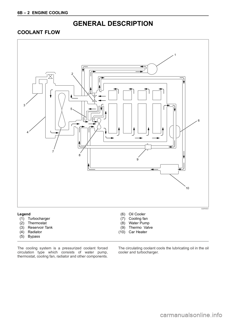
6B – 2 ENGINE COOLING
Legend
(1) Turbocharger
(2) Thermostat
(3) Reservoir Tank
(4) Radiator
(5) Bypass(6) Oil Cooler
(7) Cooling fan
(8) Water Pump
(9) Thermo Valve
(10) Car Heater
GENERAL DESCRIPTION
COOLANT FLOW
1
6
9
10
8
4
325
7
032RW001
The cooling system is a pressurized coolant forced
circulation type which consists of water pump,
thermostat, cooling fan, radiator and other components. The circulating coolant cools the lubricating oil in the oil
cooler and turbocharger.
Page 5374 of 6000

ENGINE COOLING 6B – 5
ENGINE COOLANT CHANGE
PROCEDURE
1. To change engine coolant, make sure that the
engine is cool.
WARNING:
When the coolant is heated to a high temperature,
be sure not to loosen or remove the radiator cap.
Otherwise you might get scalded by hot vapor or
boiling water. To open the radiator cap, put a piece
of thick cloth on the cap and loosen the cap slowly
to reduce the pressure once the coolant has
become cooler.
2. Open radiator cap and drain the cooling system by
loosening the drain valve on the radiator and on the
cylinder body.
NOTE: For best results it is suggested that the engine
cooling system be flushed at least once a year. It is
advisable to flush the interior of the cooling system
including the radiator before using anti-freeze
(ethylene-glycol based).
Replace damaged rubber hoses as the engine anti-
freeze coolant is liable to leak out even minor cracks.
Isuzu recommends using Isuzu genuine anti-freeze
(ethylene-glycol based) or equivalent, for the cooling
system and not add any inhibitors or additives.
CAUTION:
A failure to correctly fill the engine cooling system
in changing or topping off coolant may sometimes
cause the coolant to overflow from the filler neck
even before the engine and radiator are completely
full.
If the engine runs under this condition, shortage of
coolant may possibly result in engine overheating.
To avoid such trouble, the following precautions
should be taken in filling the system.
3. To refill engine coolant, pour coolant up to filler neck
using a filling hose which is smaller in outside
diameter than the filler neck. Otherwise air between
the filler neck and the filling hose will block entry,
preventing the system from completely filling up.
4. Keep a filling rate of 9 liter/min. or less. Filling over
this maximum rate may force air inside the engine
and radiator.
And also, the coolant overflow will increase, making
it difficult to determine whether or not the system is
completely full.
5. After filling the system full, pull out the filling hose
and check to see if air trapped in the system is
dislodged and the coolant level goes down. Should
the coolant level go down, repeat topping-off until
there is no more drop in the coolant level.
6. Directly after filling the radiator, fill the reservoir to
the maximum level.
7. Install and tighten radiator cap and start the engine.
After idling for 2 to 3 minutes, stop the engine and
reopen radiator cap. If the water level is lower,
replenish.WARNING:
When the coolant is heated to a high temperature,
be sure not to loosen or remove the radiator cap.
Otherwise you might get scalded by hot vapor or
boiling water. To open the radiator cap, put a piece
of thick cloth on the cap and loosen the cap slowly
to reduce the pressure once the coolant has
become cooler.
8. After tightening radiator cap, warm up the engine at
about 2,000 rpm.
Set heater adjustment to the highest temperature
position, and let the coolant circulate also into
heater water system.
9. Check to see the thermostat has opened by the
needle position of a water thermometer, conduct a
5-minute idle again and stop the engine.
10. When the engine has been cooled, check filler neck
for water level and replenish if required. Should
extreme shortage of coolant be found, check the
coolant system and reservoir tank hose for leakage.
11. Fill the coolant into the reservoir tank up to “MAX”
line.
Page 5426 of 6000

ENGINE ELECTRICAL 6D – 23
QOS4 PREHEATING SYSTEM
GENERAL DESCRIPTION
QOS4 preheating system features a quick-on glow plug
with thermometer control of the glowing time and the
afterglow time function.
The system consists of the ECM, indicator lamp, ECT
sensor, vehicle speed sensor, relay and temperature
self-control type glow plugs.With the employment of the ECT sensor, the glow time
changes according to the engine coolant temperature,
thus allowing optimum starting conditions to be
obtained.
The after glow time function is controlled by ECM.
NOTE:
Refer to DTC P0380 and P0381 of 6E section.
SYSTEM DIAGRAM
+
-KEY
50A
ECM
50A
GLOW
50A
2
WHT/
RED
0.5
BLK/
BLU
ECM J1-15 3
WHT/
RED
3
RED/
BLKMAIN
80A
8BLK/RED
Glow
Relay
GLOW PLUG 4
BATTHeater & A/C
Relay
060RW132