1998 OPEL FRONTERA sensor
[x] Cancel search: sensorPage 5819 of 6000
7A–38 AUTOMATIC TRANSMISSION (AW30-40LE)
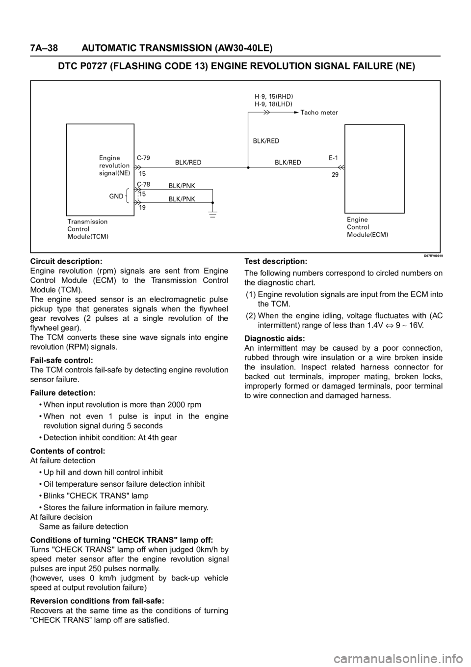
DTC P0727 (FLASHING CODE 13) ENGINE REVOLUTION SIGNAL FAILURE (NE)
D07RY00019Circuit description:
Engine revolution (rpm) signals are sent from Engine
Control Module (ECM) to the Transmission Control
Module (TCM).
The engine speed sensor is an electromagnetic pulse
pickup type that generates signals when the flywheel
gear revolves (2 pulses at a single revolution of the
flywheel gear).
The TCM converts these sine wave signals into engine
revolution (RPM) signals.
Fail-safe control:
The TCM controls fail-safe by detecting engine revolution
sensor failure.
Failure detection:
• When input revolution is more than 2000 rpm
• When not even 1 pulse is input in the engine
revolution signal during 5 seconds
• Detection inhibit condition: At 4th gear
Contents of control:
At failure detection
• Up hill and down hill control inhibit
• Oil temperature sensor failure detection inhibit
• Blinks "CHECK TRANS" lamp
• Stores the failure information in failure memory.
At failure decision
Same as failure detection
Conditions of turning "CHECK TRANS" lamp off:
Turns "CHECK TRANS" lamp off when judged 0km/h by
speed meter sensor after the engine revolution signal
pulses are input 250 pulses normally.
(however, uses 0 km/h judgment by back-up vehicle
speed at output revolution failure)
Reversion conditions from fail-safe:
Recovers at the same time as the conditions of turning
“CHECK TRANS” lamp off are satisfied.Test description:
The following numbers correspond to circled numbers on
the diagnostic char t.
(1) Engine revolution signals are input from the ECM into
the TCM.
(2) When the engine idling, voltage fluctuates with (AC
intermittent) range of less than 1.4V
9 16V.
Diagnostic aids:
An intermittent may be caused by a poor connection,
rubbed through wire insulation or a wire broken inside
the insulation. Inspect related harness connector for
backed out terminals, improper mating, broken locks,
improperly formed or damaged terminals, poor terminal
to wire connection and damaged harness.
Page 5821 of 6000
7A–40 AUTOMATIC TRANSMISSION (AW30-40LE)
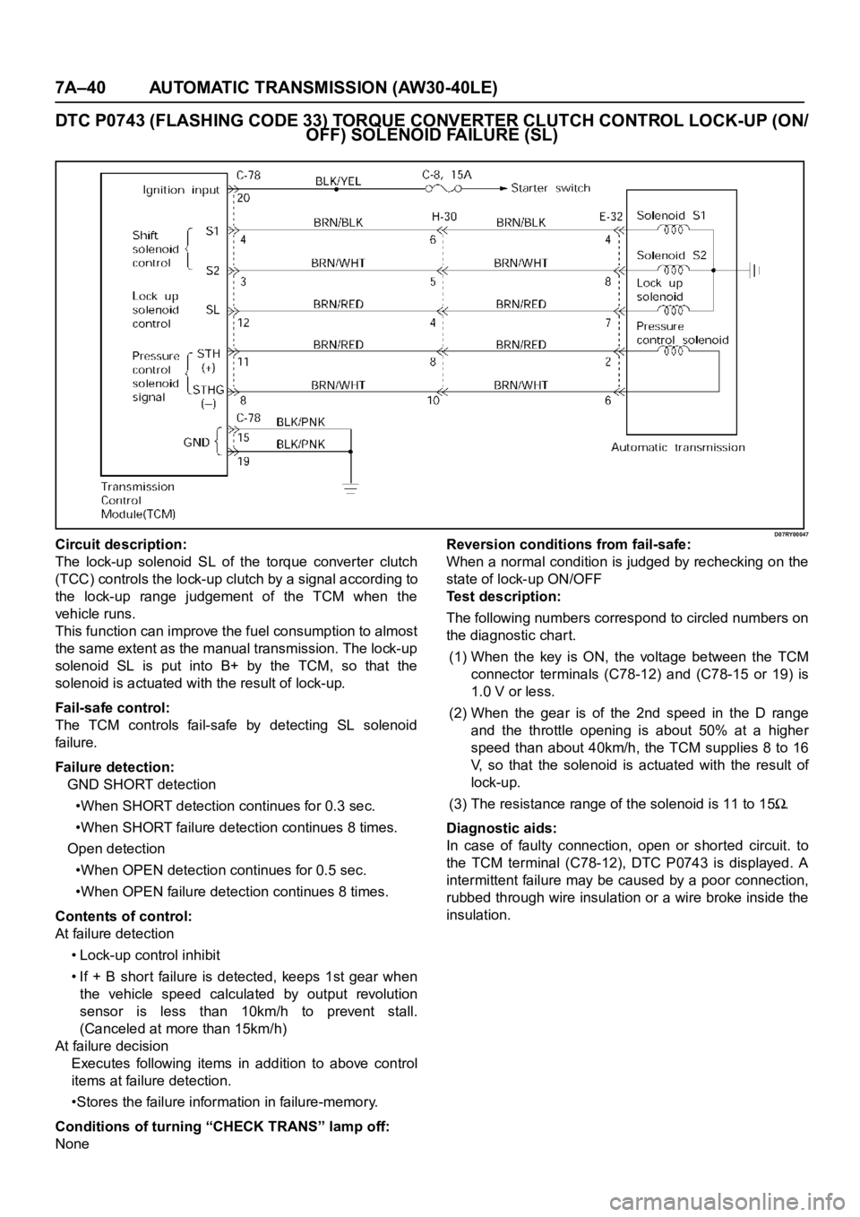
DTC P0743 (FLASHING CODE 33) TORQUE CONVERTER CLUTCH CONTROL LOCK-UP (ON/
OFF) SOLENOID FA I L U R E ( S L )
D07RY00047Circuit description:
The lock-up solenoid SL of the torque converter clutch
(TCC) controls the lock-up clutch by a signal according to
the lock-up range judgement of the TCM when the
vehicle runs.
This function can improve the fuel consumption to almost
the same extent as the manual transmission. The lock-up
solenoid SL is put into B+ by the TCM, so that the
solenoid is actuated with the result of lock-up.
Fail-safe control:
The TCM controls fail-safe by detecting SL solenoid
fai lu re.
Failure detection:
GND SHORT detection
•When SHORT detection continues for 0.3 sec.
•When SHORT failure detection continues 8 times.
Open detection
•When OPEN detection continues for 0.5 sec.
•When OPEN failure detection continues 8 times.
Contents of control:
At failure detection
• Lock-up control inhibit
• If + B short failure is detected, keeps 1st gear when
the vehicle speed calculated by output revolution
sensor is less than 10km/h to prevent stall.
(Canceled at more than 15km/h)
At failure decision
Executes following items in addition to above control
items at failure detection.
•Stores the failure information in failure-memory.
Conditions of turning “CHECK TRANS” lamp off:
NoneReversion conditions from fail-safe:
When a normal condition is judged by rechecking on the
state of lock-up ON/OFF
Test description:
The following numbers correspond to circled numbers on
the diagnostic char t.
(1) When the key is ON, the voltage between the TCM
connector terminals (C78-12) and (C78-15 or 19) is
1.0 V or less.
(2) When the gear is of the 2nd speed in the D range
and the throttle opening is about 50% at a higher
speed than about 40km/h, the TCM supplies 8 to 16
V, so that the solenoid is actuated with the result of
lock-up.
(3) The resistance range of the solenoid is 11 to 15
.
Diagnostic aids:
In case of faulty connection, open or shorted circuit. to
the TCM terminal (C78-12), DTC P0743 is displayed. A
intermittent failure may be caused by a poor connection,
rubbed through wire insulation or a wire broke inside the
insulation.
Page 5823 of 6000
7A–42 AUTOMATIC TRANSMISSION (AW30-40LE)
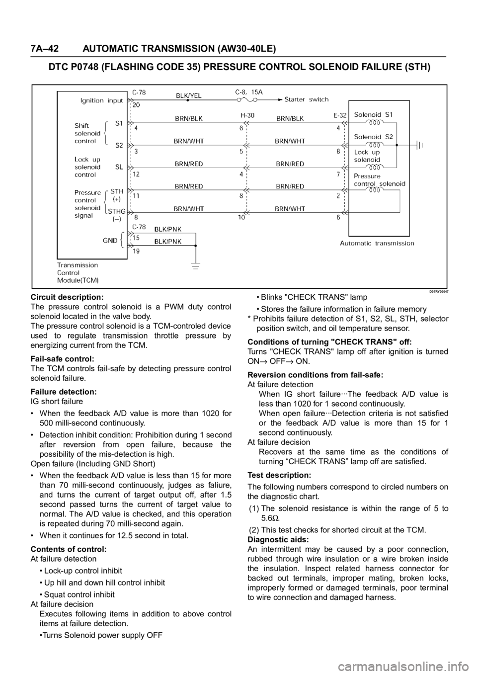
DTC P0748 (FLASHING CODE 35) PRESSURE CONTROL SOLENOID FAILURE (STH)
D07RY00047Circuit description:
The pressure control solenoid is a PWM duty control
solenoid located in the valve body.
The pressure control solenoid is a TCM-controled device
used to regulate transmission throttle pressure by
energizing current from the TCM.
Fail-safe control:
The TCM controls fail-safe by detecting pressure control
solenoid failure.
Failure detection:
IG shor t failure
• When the feedback A/D value is more than 1020 for
500 milli-second continuously.
• Detection inhibit condition: Prohibition during 1 second
after reversion from open failure, because the
possibility of the mis-detection is high.
Open failure (Including GND Shor t)
• When the feedback A/D value is less than 15 for more
than 70 milli-second continuously, judges as faliure,
and turns the current of target output off, after 1.5
second passed turns the current of target value to
normal. The A/D value is checked, and this operation
is repeated during 70 milli-second again.
• When it continues for 12.5 second in total.
Contents of control:
At failure detection
• Lock-up control inhibit
• Up hill and down hill control inhibit
• Squat control inhibit
At failure decision
Executes following items in addition to above control
items at failure detection.
•Turns Solenoid power supply OFF• Blinks "CHECK TRANS" lamp
• Stores the failure information in failure memory
* Prohibits failure detection of S1, S2, SL, STH, selector
position switch, and oil temperature sensor.
Conditions of turning "CHECK TRANS" off:
Turns "CHECK TRANS" lamp off after ignition is turned
ON
OFF ON.
Reversion conditions from fail-safe:
At failure detection
W h e n I G sh o r t fa i l u re ꞏꞏꞏT h e fe e d ba ck A / D va l u e i s
less than 1020 for 1 second continuously.
W h e n o p e n fa i l u re ꞏꞏꞏD e t e c t i o n c r i t e r i a i s n o t s a t i s f i e d
or the feedback A/D value is more than 15 for 1
second continuously.
At failure decision
Recovers at the same time as the conditions of
turning “CHECK TRANS” lamp off are satisfied.
Test description:
The following numbers correspond to circled numbers on
the diagnostic char t.
(1) The solenoid resistance is within the range of 5 to
5.6
.
(2) This test checks for shor ted circuit at the TCM.
Diagnostic aids:
An intermittent may be caused by a poor connection,
rubbed through wire insulation or a wire broken inside
the insulation. Inspect related harness connector for
backed out terminals, improper mating, broken locks,
improperly formed or damaged terminals, poor terminal
to wire connection and damaged harness.
Page 5826 of 6000

AUTOMATIC TRANSMISSION (AW30-40LE) 7A–45
• Changes solenoid output pattern as following figure
The shift theory at shift solenoid failure
At failure decision
Executes following items in addition to above control
items at failure detection.
•Turns Solenoid power supply OFF
•Blinks "CHECK TRANS" lamp
•Stores the failure information in failure-memory
*Prohibits failure detection of S1, S2, SL, STH,
Selector position switch, and Oil temp. sensor.
Conditions of turning "CHECK TRANS" off:
Turns "CHECK TRANS" lamp off after ignition is turned
ON
OFF ON.
Reversion conditions from fail-safe:
At failure detection
When a normal judgment is obtained by rechecking
during shifting.
At failure decision
Recovers at the same time as the conditions of
turning “CHECK TRANS” lamp off are satisfied.
Test description:
The following numbers correspond to circled numbers on
the diagnostic char t.
(1) With the key "ON", the voltage between the TCM
terminals (C78-4) and (C78-15 or 19) is 8 to 16V.
(2) When the driving wheels revolve with the 3rd speed
gear, the voltage is 1 V or less.
(3) The solenoid resistance is within the range of 11 to
15
.
Diagnostic aids:
In case of faulty connection, open or shor ted circuit to
the TCM terminal (C78-4), DTC P0753 is displayed. A
intermittent failure may be caused by a poor connection,
rubbed through wire insulation or a wire broke inside the
insulation.Shift
lever
Po s i t i o nNormal S1 failure S2 filure S1 and S2 failure
Gear S1 S2 Gear S1 S2 Gear S1 S2 Gear S1 S2
D1
3
1
O/D 2O/D3
O/DO/D
213
1
3 2O/D3
L1313
2O/D
Page 5829 of 6000
7A–48 AUTOMATIC TRANSMISSION (AW30-40LE)
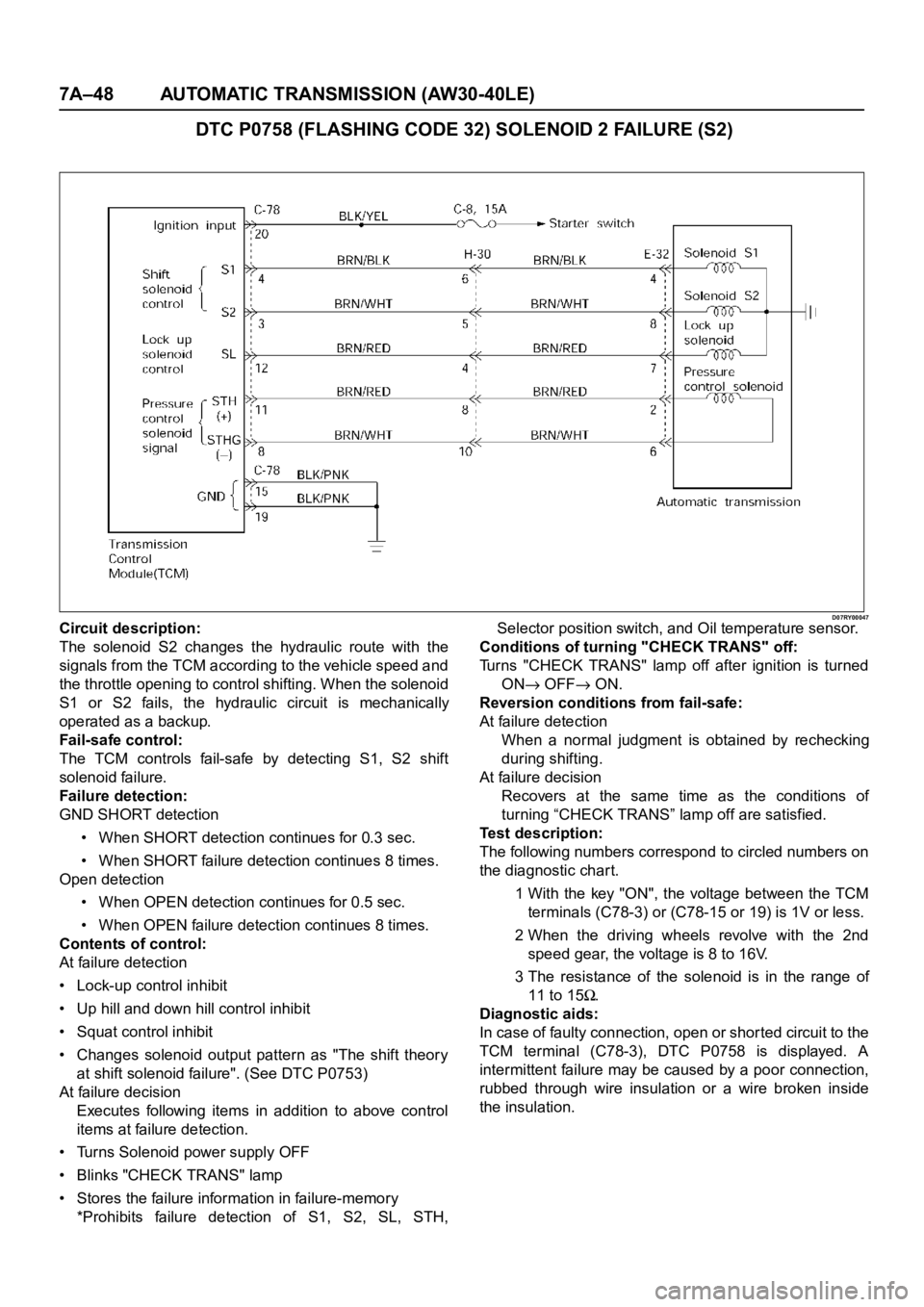
DTC P0758 (FLASHING CODE 32) SOLENOID 2 FAILURE (S2)
D07RY00047Circuit description:
The solenoid S2 changes the hydraulic route with the
signals from the TCM according to the vehicle speed and
the throttle opening to control shifting. When the solenoid
S1 or S2 fails, the hydraulic circuit is mechanically
operated as a backup.
Fail-safe control:
The TCM controls fail-safe by detecting S1, S2 shift
solenoid failure.
Failure detection:
GND SHORT detection
• When SHORT detection continues for 0.3 sec.
• When SHORT failure detection continues 8 times.
Open detection
• When OPEN detection continues for 0.5 sec.
• When OPEN failure detection continues 8 times.
Contents of control:
At failure detection
• Lock-up control inhibit
• Up hill and down hill control inhibit
• Squat control inhibit
• Changes solenoid output pattern as "The shift theory
at shift solenoid failure". (See DTC P0753)
At failure decision
Executes following items in addition to above control
items at failure detection.
• Turns Solenoid power supply OFF
• Blinks "CHECK TRANS" lamp
• Stores the failure information in failure-memory
*Prohibits failure detection of S1, S2, SL, STH,Selector position switch, and Oil temperature sensor.
Conditions of turning "CHECK TRANS" off:
Turns "CHECK TRANS" lamp off after ignition is turned
ON
OFF ON.
Reversion conditions from fail-safe:
At failure detection
When a normal judgment is obtained by rechecking
during shifting.
At failure decision
Recovers at the same time as the conditions of
turning “CHECK TRANS” lamp off are satisfied.
Test description:
The following numbers correspond to circled numbers on
the diagnostic char t.
1 With the key "ON", the voltage between the TCM
terminals (C78-3) or (C78-15 or 19) is 1V or less.
2 When the driving wheels revolve with the 2nd
speed gear, the voltage is 8 to 16V.
3 The resistance of the solenoid is in the range of
11 to 15
.
Diagnostic aids:
In case of faulty connection, open or shor ted circuit to the
TCM terminal (C78-3), DTC P0758 is displayed. A
intermittent failure may be caused by a poor connection,
rubbed through wire insulation or a wire broken inside
the insulation.
Page 5831 of 6000
7A–50 AUTOMATIC TRANSMISSION (AW30-40LE)
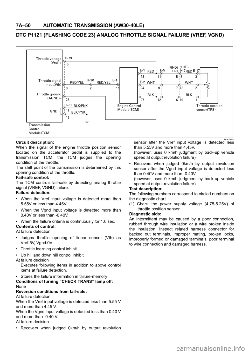
DTC P1121 (FLASHING CODE 23) ANALOG THROTTLE SIGNAL FAILURE (VREF, VGND)
D07RY00023Circuit description:
When the signal of the engine throttle position sensor
located on the accelerator pedal is supplied to the
transmission TCM, the TCM judges the opening
condition of the throttle.
The shift point of the transmission is determined by this
opening condition of the throttle.
Fail-safe control:
The TCM controls fail-safe by detecting analog throttle
signal (VREF, VGND) failure.
Failure detection:
• When the Vref input voltage is detected more than
5.55V or less than 4.45V.
• When the Vgnd input voltage is detected more than
0.40V or less than -0.40V.
• When the failure criteria is continuously for 1.0 sec.
Contents of control:
At failure detection
• Judges throttle opening of linear sensor (Vth) as
Vref:5V, Vgnd:0V
• Throttle learning control inhibit
• Up hill and down hill control inhibit
At failure decision
Executes following items in addition to above control
items at failure detection.
• Stores the failure information in failure-memory
Conditions of turning “CHECK TRANS” lamp off:
None
Reversion conditions from fail-safe:
At failure detection
When the Vref input voltage is detected less than 5.55 V
and more than 4.45 V.
When the Vgnd input voltage is detected less than 0.40 V
and more than -0.40 V.
At failure decision
• Recovers when judged 0km/h by output revolutionsensor after the Vref input voltage is detected less
than 5.55V and more than 4.45V.
(however, uses 0 km/h judgment by back-up vehicle
speed at output revolution failure)
• Recovers when judged 0km/h by output revolution
sensor after the Vgnd input voltage is detected less
than 0.40V and more than -0.40V.
(however, uses 0 km/h judgment by back-up vehicle
speed at output revolution failure)
Test description:
The following numbers correspond to circled numbers on
the diagnostic char t.
(1) Check the power supply voltage (4.75-5.25V) of
throttle position sensor.
Diagnostic aids:
An intermittent may be caused by a poor connection,
rubbed through wire insulation or a wire broken inside
the insulation. Inspect related harness connector for
backed out terminals, improper mating, broken locks,
improperly formed or damaged terminals, poor terminal
to wire connection and damaged harness.
Page 5852 of 6000
AUTOMATIC TRANSMISSION (AW30-40LE) 7A–71
826RY00017
TCM VOLTAGE CHECK
TCM voltage check is done to check for transmission and
transmission control module (TCM) problems which cannot be
detected by self-diagnosis.
Additionally, it serves as a back-up check for self-diagnosis.
Measure the voltage drop and make a continuity test for each
of the sensors, solenoids, and switches.
If the voltage is within the specified range and continuity exists,
that particular area of the TCM and automatic transmission
assembly is normal.
If voltage deviation or lack of continuity is discovered,
disconnect the applicable parts and check each of them
individually.
This will allow you to determine the trouble location (TCM,
automatic transmission unit, or another area of the vehicle).
Inspection Tool
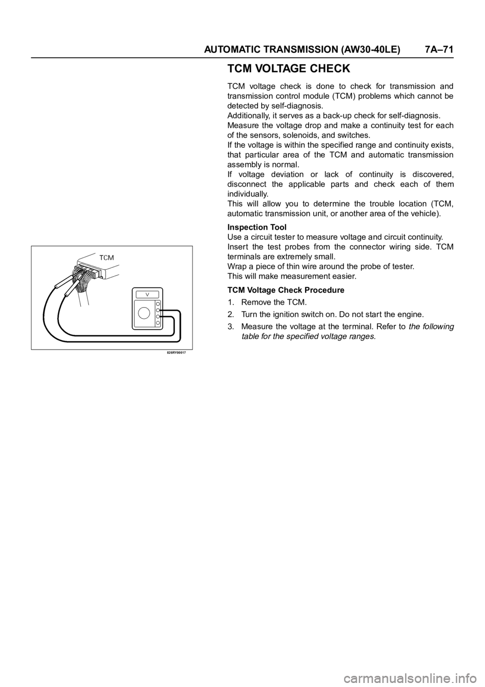
Use a circuit tester to measure voltage and circuit continuity.
Inser t the test probes from the connector wiring side. TCM
terminals are extremely small.
Wrap a piece of thin wire around the probe of tester.
This will make measurement easier.
TCM Voltage Check Procedure
1. Remove the TCM.
2. Turn the ignition switch on. Do not start the engine.
3. Measure the voltage at the terminal. Refer to
the following
table for the specified voltage ranges.
Page 5853 of 6000

7A–72 AUTOMATIC TRANSMISSION (AW30-40LE)
TCM STANDARD VOLTAGE
Check circuitTe r m i n a l
Measuring condition Voltage (V)
+-
Throttle position sensorC79-6 C79-28Throttle fully opened (WOT) 3.47
4.56
Throttle fully closed (idling) 0.25
0.45
C79-19 C79-18 Key switch ON 4.75
5.25
Output revolution sensor C79-4 C79-16 Engine idling in gear 0
3
Input revolution sensor C79-5 C79-17 Engine idling 0
3
Speed meter sensor C79-7C78-15
or -19Vehicle speed 10
20 km/h Less than 1.4
about 5
Brake switch C78-18C78-15
or -19Depress brake 7
16
Release brake Less than 1
O/D OFF switch C79-3C78-15
or -19O/D OFF switch ON (O/D OFF) 7
16
O/D OFF switch OFF (O/D ON) Less than 1
Neutral start switch
C79-2C78-15
or -19Selector “P” range 7
16
(P) Selector all ranges except “P” Less than 1
Neutral start switch
C79-1C78-15
or -19Selector “R” range 7
16
(R) Selector all ranges except “R” Less than 1
Neutral start switch
C79-9C78-15
or -19Selector “N” range 7
16
(N) Selector all ranges except “N” Less than 1
Neutral start switch
C79-8C78-15
or -19Selector “D” range 7
16
(D) Selector all ranges except “D” Less than 1
Neutral start switch
C79-21C78-15
or -19Selector “2” range 7
16
(2) Selector all ranges except “2” Less than 1
Neutral start switch
C79-20C78-15
or -19Selector “L” range 7
16
(L) Selector all ranges except “L” Less than 1
Engine revolution signal C79-15C78-15
or -19Engine idling Less than 1.4
9 16
Diagnosis terminal C79-24C78-15
or -19Self-diagnosis ON
0
1.5
Power pattern switch C79-23C78-15
or -19Power pattern switch OFF (NORMAL) 8
16
Power pattern switch ON (POWER) Less than 1.4
Winter select switch C79-13C78-15
or -19Switch OFF 8
16
Switch ON Less than 1.4
Electrical source (Battery) C78-13C78-15
or -19—
9
16
Electrical source (Ignition) C78-20C78-15
or -19Key switch ON
9
16
Oil temperature warning lamp C79-11C78-15
or -19Oil temperature warning lamp ON Less than 1
Oil temperature warning lamp OFF 8
16
“CHECK TRANS lamp” C79-10C78-15
or -19“CHECK TRANS” lamp ON Less than 1
“CHECK TRANS” lamp OFF 8
16
Power lamp C79-22C78-15
or -19Power lamp ON Less than 1
Powe r l a m p O F F 8
16