1998 OPEL FRONTERA sensor
[x] Cancel search: sensorPage 5854 of 6000
 7A–73
Check circuitTe r m i n a l
Measuring condition Voltage (V)
+-
Winter lamp C79-12C78-15
or -19Winter lamp ON Less than 1
Winter lamp OFF 8
16
Solenoid S1")
AUTOMATIC TRANSMISSION (AW30-40LE) 7A–73
Check circuitTe r m i n a l
Measuring condition Voltage (V)
+-
Winter lamp C79-12C78-15
or -19Winter lamp ON Less than 1
Winter lamp OFF 8
16
Solenoid S1 C78-4C78-15
or -19OFF (3rd or O/D) Less than 1
ON (1st or 2nd) 8
16
Solenoid S2 C78-3C78-15
or -19OFF (1st or O/D) Less than 1
ON (2nd or 3rd) 8
16
Lock up solenoid SL C78-12C78-15
or -19OFF (Lock up OFF) Less than 1
ON (Lock up ON) 8
16
Pressure control solenoid C78-11 C78-8At throttle pressure changing Less than
1
8-16
Oil temperature sensor C79-18 C79-27ATF temperature 20
C4.70
ATF temperature 80
C3.65
Tech 2 diagnosis terminal
(J1850)C78-6C78-15
or -19On diagnosis communication 0-1.5
6.25-8.0
Throttle position sensor
(ground)C79-19C78-15
or -19Key switch ON
-0.1
0.1
Page 5858 of 6000
 7A–77
310RW020
F07RY00017
F07RY00018
BRAKE SIGNAL INSPECTION
Check that the brake light comes on when the brake pedal is
depressed.
VEHICLE SPEED SENSOR")
AUTOMATIC TRANSMISSION (AW30-40LE) 7A–77
310RW020
F07RY00017
F07RY00018
BRAKE SIGNAL INSPECTION
Check that the brake light comes on when the brake pedal is
depressed.
VEHICLE SPEED SENSOR INSPECTION
1. Connect the Vehicle speed sensor connector terminal (1) to
the battery ( +) terminal and terminal (2) to the battery (-)
terminal.
2. Connect a resistance of 1.3k ohm to 5k ohm (1.4W or
more) between terminals (1) and (3).
NOTE:
Be extremely careful not to connect the battery (+) terminal
to the terminal (3)
This may damage the vehicle speed sensor.
3. Rotate the shaft of the vehicle speed sensor slowly and
measure the voltage at both ends with a digital tester.
Replace the sensor when the result of inspection is found
abnormal.
INPUT AND OUTPUT REVOLUTION
SENSOR INSPECTION
Use an ohmmeter to measure the resistance between
terminals 1 and 2.The voltage, with one rotation of shaft, fluctuates four
times in the following range: 10 to 14V
2V or less.
Standard resistance 560 – 680
(20C)
610 – 740
(40C)
Page 5860 of 6000
AUTOMATIC TRANSMISSION (AW30-40LE) 7A–79
244RY00005
101RY00004
249RW003
242RW013
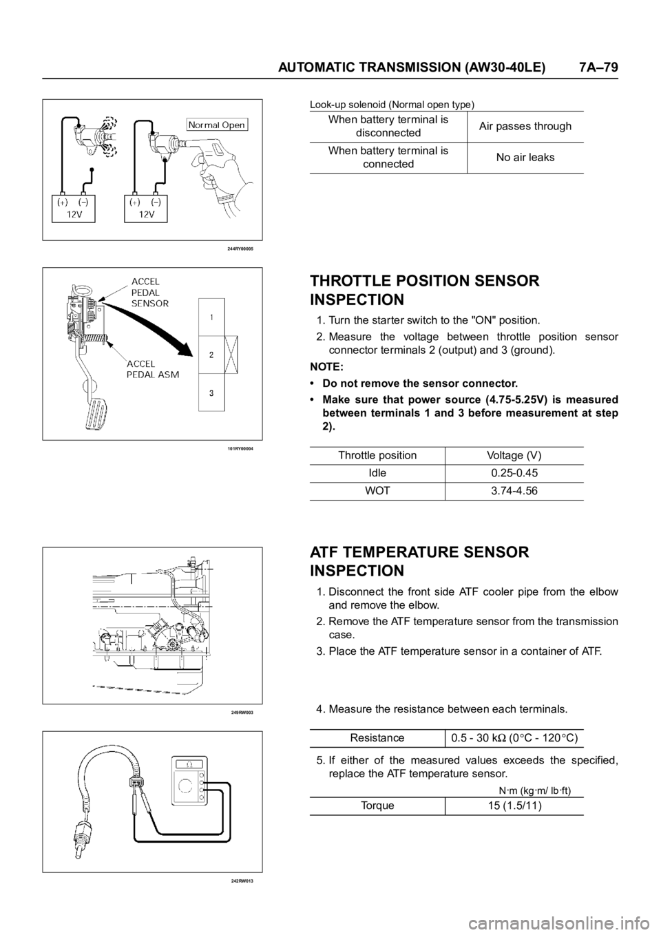
Look-up solenoid (Normal open type)
THROTTLE POSITION SENSOR
INSPECTION
1. Turn the starter switch to the "ON" position.
2. Measure the voltage between throttle position sensor
connector terminals 2 (output) and 3 (ground).
NOTE:
• Do not remove the sensor connector.
• Make sure that power source (4.75-5.25V) is measured
between terminals 1 and 3 before measurement at step
2).
ATF TEMPERATURE SENSOR
INSPECTION
1. Disconnect the front side ATF cooler pipe from the elbow
and remove the elbow.
2. Remove the ATF temperature sensor from the transmission
case.
3. Place the ATF temperature sensor in a container of ATF.
4. Measure the resistance between each terminals.
5. If either of the measured values exceeds the specified,
replace the ATF temperature sensor.
Nꞏm (kgꞏm/ lbꞏft)
When battery terminal is
disconnectedAir passes through
When battery terminal is
connectedNo air leaks
Throttle position Voltage (V)
Idle 0.25-0.45
WOT 3.74-4.56
Resistance 0.5 - 30 k
(0C - 120C)
Torque 15 (1.5/11)
Page 5872 of 6000
 7A–91
UNIT REPAIR
DISASSEMBLY OF MAJOR COMPONENTS (1)
240RY00024
NOTE:
Steps marked with a triangle (
) are important
operations. Detailed information app")
AUTOMATIC TRANSMISSION (AW30-40LE) 7A–91
UNIT REPAIR
DISASSEMBLY OF MAJOR COMPONENTS (1)
240RY00024
NOTE:
Steps marked with a triangle (
) are important
operations. Detailed information appears in the text.
Disassembly steps
1. Torque conver ter
2. Breather hose
3. Transmission ocntrol rod and shift lever
4. Neutral start switch
5. Elbow
6. Oil temperature sensor
7. Input revolution sensor
8. Output revolution sensor
9. Adapter housing
10. Transmission assembly
Page 5985 of 6000

REASSEMBLY OF MAJOR COMPONENTS (3)
240RY00030
Reassembly steps
1. Transmission assembly
2. Converter housing
3. Adapter housing
4. Oil temperature sensor")
7A–204 AUTOMATIC TRANSMISSION (AW30-40LE)
REASSEMBLY OF MAJOR COMPONENTS (3)
240RY00030
Reassembly steps
1. Transmission assembly
2. Converter housing
3. Adapter housing
4. Oil temperature sensor
5. Elbow
6. Neutral star t switch
7. Transmission control rod and shift lever
8. Input revolution sensor
9. Output revolution sensor
10. Breather hose
11. Torque converter
Page 5986 of 6000
 7A–205
240RY00006
240RY00003
241RY00020
Important operations
2. Converter housing
3. Adapter housing
Oil seal replacement
(1)Using a screwdriver, remove the oil se")
AUTOMATIC TRANSMISSION (AW30-40LE) 7A–205
240RY00006
240RY00003
241RY00020
Important operations
2. Converter housing
3. Adapter housing
Oil seal replacement
(1)Using a screwdriver, remove the oil seal.
(2)Apply ATF to a new oil seal lip.
(3)Using special tool, install the oil seal.
Installer:5–8840–2282–0
Remove any gasket material on the contacting surfaces of
the adapter case and transmission case.
Apply liquid gasket (TB1281–B or its equivalent) (1) and
install the apply gaskets (2) to the adapter case as shown
in the figure.
Install the adapter housing to the transmission case.
4. Oil temperature sensor
Install the oil temperature sensor to the transmission case.Nꞏm (kgꞏm/lbꞏft)
To r q u eM10 34 (3.5/25)
M12 57 (5.8/42)
Nꞏm (kgꞏm/lbꞏft)
Torque 34 (3.5/25)
Nꞏm (kgꞏm/lbꞏft)
Torque 15 (1.5/11)
Page 5994 of 6000
7A1–1
TRANSMISSION
TRANSMISSION CONTROL SYSTEM (4L30–E)
CONTENTS
Service Precaution 7A1–2. . . . . . . . . . . . . . . . . . . . . .
General Description 7A")
TRANSMISSION CONTROL SYSTEM (4L30–E)7A1–1
TRANSMISSION
TRANSMISSION CONTROL SYSTEM (4L30–E)
CONTENTS
Service Precaution 7A1–2. . . . . . . . . . . . . . . . . . . . . .
General Description 7A1–2. . . . . . . . . . . . . . . . . . . . .
Electronic Control Diagram 7A1–3. . . . . . . . . . . . .
Powertrain Control Module (PCM) 7A1–4. . . . . . .
Control System Diagram 7A1–5. . . . . . . . . . . . . . .
Shift Control 7A1–6. . . . . . . . . . . . . . . . . . . . . . . . . .
Band Apply Control 7A1–6. . . . . . . . . . . . . . . . . . . .
Torque Converter Clutch Control 7A1–6. . . . . . . . .
Line Pressure Control 7A1–6. . . . . . . . . . . . . . . . . .
On–Board Diagnostic System 7A1–6. . . . . . . . . . .
Fail Safe Mechanism 7A1–6. . . . . . . . . . . . . . . . . . .
Torque Management Control 7A1–6. . . . . . . . . . . .
ATF Warning Control 7A1–6. . . . . . . . . . . . . . . . . . .
ABS Control (If equipped) 7A1–6. . . . . . . . . . . . . .
Shift Mode Control 7A1–7. . . . . . . . . . . . . . . . . . . . .
Gear Shift Control 7A1–8. . . . . . . . . . . . . . . . . . . . .
Winter Drive Mode 7A1–9. . . . . . . . . . . . . . . . . . . . .
Backup Mode 7A1–9. . . . . . . . . . . . . . . . . . . . . . . . .
Functions of Input / Output Components 7A1–10. .
Diagnosis 7A1–11. . . . . . . . . . . . . . . . . . . . . . . . . . . . . .
Electronic Diagnosis 7A1–11. . . . . . . . . . . . . . . . . . .
Check Trans Indicator 7A1–11. . . . . . . . . . . . . . . . . .
Diagnostic Check 7A1–11. . . . . . . . . . . . . . . . . . . . . .
“Check Trans” Check 7A1–12. . . . . . . . . . . . . . . . . .
Tech2 OBD II Connection 7A1–13. . . . . . . . . . . . . . .
F0: Transmission Data 7A1–18. . . . . . . . . . . . . . . . .
F1: PC Solenoid Data 7A1–19. . . . . . . . . . . . . . . . . .
OBD II Diagnostic Management System 7A1–20. .
16 – Terminal Data Link Connector (DLC) 7A1–21.
Malfunction Indicator Lamp (MIL) 7A1–22. . . . . . . .
Types Of Diagnostic Trouble Codes (DTCs) 7A1–22
Clear DTC 7A1–22. . . . . . . . . . . . . . . . . . . . . . . . . . . .
DTC Check 7A1–23. . . . . . . . . . . . . . . . . . . . . . . . . . .
PCM Precaution 7A1–23. . . . . . . . . . . . . . . . . . . . . . .
Information On PCM 7A1–23. . . . . . . . . . . . . . . . . . .
Intermittent Conditions 7A1–23. . . . . . . . . . . . . . . . . Transmission And PCM Identification 7A1–24. . . . .
Isuzu Trooper 7A1–25. . . . . . . . . . . . . . . . . . . . . . . . .
Diagnostic Trouble Code (DTC)
Identification 7A1–26. . . . . . . . . . . . . . . . . . . . . . . . .
DTC P0218 Transmission Fluid Over
Temperature 7A1–27. . . . . . . . . . . . . . . . . . . . . . . . . . .
DTC P0560 System Voltage Malfunction 7A1–29. . .
DTC P0705 Transmission Range Switch
(Mode Switch) Illegal Position 7A1–32. . . . . . . . . . . .
DTC P0706 Transmission Range Switch
(Mode Switch) Performance 7A1–35. . . . . . . . . . . . . .
DTC P0712 Transmission Fluid Temperature
(TFT) Sensor Circuit Low Input 7A1–38. . . . . . . . . . .
DTC P0713 Transmission Fluid Temperature
(TFT) Sensor Circuit High Input 7A1–41. . . . . . . . . . .
DTC P0719 TCC Brake Switch Circuit High
(Stuck On) 7A1–44. . . . . . . . . . . . . . . . . . . . . . . . . . . . .
DTC P0722 Transmission Output Speed
Sensor (OSS) Low Input 7A1–47
. . . . . . . . . . . . . . . . .
DTC P0723 Transmission Output Speed
Sensor (OSS) Intermittent 7A1–50. . . . . . . . . . . . . . .
DTC P0730 Transmission Incorrect Gear
Ratio 7A1–53. . . . . . . . . . . . . . . . . . . . . . . . . . . . . . . . . .
DTC P0748 Pressure Control Solenoid
(PCS) (Force Motor) Circuit Electrical 7A1–56. . . . .
DTC P0753 Shift Solenoid A Electrical 7A1–58. . . . .
DTC P0758 Shift Solenoid B Electrical 7A1–61. . . . .
DTC P1790 ROM Transmission Side Bad
Check Sum 7A1–65. . . . . . . . . . . . . . . . . . . . . . . . . . . .
DTC P1792 EEPROM Transmission Side
Bad Check Sum 7A1–66. . . . . . . . . . . . . . . . . . . . . . . .
DTC P1835 Kickdown Switch Always On 7A1–67. . .
DTC P1850 Brake Band Apply Solenoid
Malfunction 7A1–69. . . . . . . . . . . . . . . . . . . . . . . . . . . .
DTC P1860 TCC Solenoid Electrical 7A1–73. . . . . . .
Transmission Fluid Temperature (TFT)
Sensor Specifications 7A1–76. . . . . . . . . . . . . . . . . . .
Page 5995 of 6000

Service Precaution
WARNING: IF SO EQUIPPED WITH A
SUPPLEMENTAL RESTRAINT SYSTEM (SRS),
REFER TO THE SRS COMPONENT AND WIRING
LOCATION VIEW I")
7A1–2
TRANSMISSION CONTROL SYSTEM (4L30–E)
Service Precaution
WARNING: IF SO EQUIPPED WITH A
SUPPLEMENTAL RESTRAINT SYSTEM (SRS),
REFER TO THE SRS COMPONENT AND WIRING
LOCATION VIEW IN ORDER TO DETERMINE
WHETHER YOU ARE PERFORMING SERVICE ON OR
NEAR THE SRS COMPONENTS OR THE SRS
WIRING. WHEN YOU ARE PERFORMING SERVICE
ON OR NEAR THE SRS COMPONENTS OR THE SRS
WIRING, REFER TO THE SRS SERVICE
INFORMATION. FAILURE TO FOLLOW WARNINGS
COULD RESULT IN POSSIBLE AIR BAG
DEPLOYMENT, PERSONAL INJURY, OR
OTHERWISE UNNEEDED SRS SYSTEM REPAIRS.
CAUTION: Always use the correct fastener in the
proper location. When you replace a fastener, use
ONLY the exact part number for that application.
ISUZU will call out those fasteners that require a
replacement after removal. ISUZU will also call out
the fasteners that require thread lockers or thread
sealant. UNLESS OTHERWISE SPECIFIED, do not
use supplemental coatings (Paints, greases, or other
corrosion inhibitors) on threaded fasteners or
fastener joint interfaces. Generally, such coatings
adversely affect the fastener torque and the joint
clamping force, and may damage the fastener. When
you install fasteners, use the correct tightening
sequence and specifications. Following these
instructions can help you avoid damage to parts and
systems.
General Description
The 4L30–E is a 4–speed fully automatic transmission. It
uses a microcomputer as a control unit to judge running
conditions including throttle opening rate and vehicle
speed, then it sets the shifting point in the optimum timing
so that best driving performance can be achieved.
In addition, the built–in shift mode select function can
select three shift modes according to the driver’s
preference:
Normal mode –Normal shift pattern.
Winter mode –Starts in 3rd gear to reduce slippage on
ice or snow.
Power mode has a delayed upshift for when more
powerful acceleration is required.
Also, the built–in fail safe function (“backup mode”)
assures driving performance even if the vehicle speed
sensor, throttle signal or any solenoid fails.
Further, the self–diagnostic function conducts diagnosis
in a short time when the control system fails, thus
improving serviceability.
The major features of 4L30–E are as follows:
A compact structure consisting of 2 sets of planetary
gears and flat torque converter.
Electronic control selects the optimum shift mode
according to the driving conditions.
Electronic control maintains the optimum hydraulic
pressure for clutch, band brake as well as
transmission so that shift feeling is improved.
Two sets of planetary gears reduce friction of power
train.
Also, a lockup mechanism in the torque converter
reduces fuel consumption.
Wide gear ratio and high torque rate of torque
converter provide excellent starting performance.