1998 OPEL FRONTERA air filter
[x] Cancel search: air filterPage 4930 of 6000
6E–273 ENGINE DRIVEABILITY AND EMISSIONS
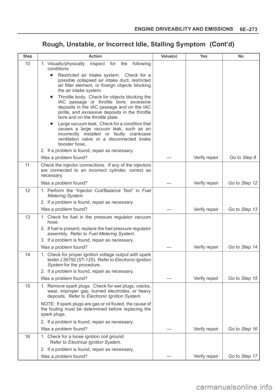
Rough, Unstable, or Incorrect Idle, Stalling Symptom
StepNo Ye s Va l u e ( s ) Action
101. Visually/physically inspect for the following
conditions:
Restricted air intake system. Check for a
possible collapsed air intake duct, restricted
air filter element, or foreign objects blocking
the air intake system.
Throttle body. Check for objects blocking the
IAC passage or throttle bore, excessive
deposits in the IAC passage and on the IAC
pintle, and excessive deposits in the throttle
bore and on the throttle plate.
Large vacuum leak. Check for a condition that
causes a large vacuum leak, such as an
incorrectly installed or faulty crankcase
ventilation valve or a disconnected brake
booster hose.
2. If a problem is found, repair as necessary.
Was a problem found?
—Verify repairGo to Step 8
11Check the injector connections. If any of the injectors
are connected to an incorrect cylinder, correct as
necessary.
Was a problem found?
—Verify repairGo to Step 12
121. Perform the “Injector Coil/Balance Test” in Fuel
Metering System
.
2. If a problem is found, repair as necessary.
Was a problem found?
—Verify repairGo to Step 13
131. Check for fuel in the pressure regulator vacuum
hose.
2. If fuel is present, replace the fuel pressure regulator
assembly. Refer to
Fuel Metering System.
3. If a problem is found, repair as necessary.
Was a problem found?
—Verify repairGo to Step 14
141. Check for proper ignition voltage output with spark
tester J 26792 (ST-125). Refer to
Electronic Ignition
System
for the procedure.
2. If a problem is found, repair as necessary.
Was a problem found?
—Verify repairGo to Step 15
151. Remove spark plugs. Check for wet plugs, cracks,
wear, improper gap, burned electrodes, or heavy
deposits. Refer to
Electronic Ignition System.
NOTE: If spark plugs are gas or oil fouled, the cause of
the fouling must be determined before replacing the
spark plugs.
2. If a problem is found, repair as necessary.
Was a problem found?
—Verify repairGo to Step 16
161. Check for a loose ignition coil ground.
Refer to
Electrical Ignition System.
2. If a problem is found, repair as necessary.
Was a problem found?
—Verify repairGo to Step 17
Page 4932 of 6000
6E–275 ENGINE DRIVEABILITY AND EMISSIONS
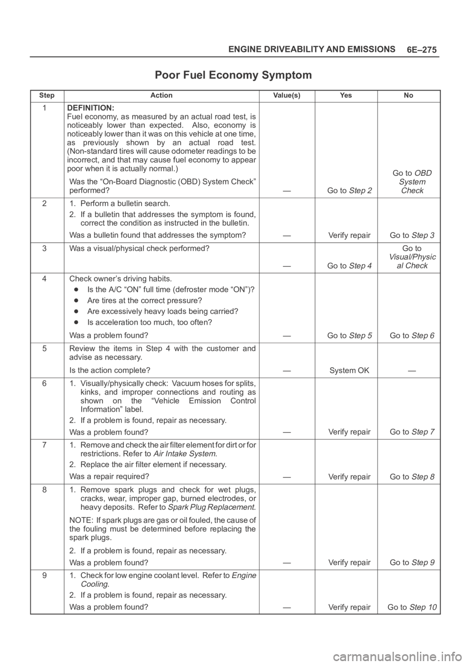
Poor Fuel Economy Symptom
StepActionVa l u e ( s )Ye sNo
1DEFINITION:
Fuel economy, as measured by an actual road test, is
noticeably lower than expected. Also, economy is
noticeably lower than it was on this vehicle at one time,
as previously shown by an actual road test.
(Non-standard tires will cause odometer readings to be
incorrect, and that may cause fuel economy to appear
poor when it is actually normal.)
Was the “On-Board Diagnostic (OBD) System Check”
performed?
—Go to Step 2
Go to OBD
System
Check
21. Perform a bulletin search.
2. If a bulletin that addresses the symptom is found,
correct the condition as instructed in the bulletin.
Was a bulletin found that addresses the symptom?
—Verify repairGo to Step 3
3Was a visual/physical check performed?
—Go to Step 4
Go to
Visual/Physic
al Check
4Check owner’s driving habits.
Is the A/C “ON” full time (defroster mode “ON”)?
Are tires at the correct pressure?
Are excessively heavy loads being carried?
Is acceleration too much, too often?
Was a problem found?
—Go to Step 5Go to Step 6
5Review the items in Step 4 with the customer and
advise as necessary.
Is the action complete?
—System OK—
61. Visually/physically check: Vacuum hoses for splits,
kinks, and improper connections and routing as
shown on the “Vehicle Emission Control
Information” label.
2. If a problem is found, repair as necessary.
Was a problem found?
—Verify repairGo to Step 7
71. Remove and check the air filter element for dirt or for
restrictions. Refer to
Air Intake System.
2. Replace the air filter element if necessary.
Was a repair required?
—Verify repairGo to Step 8
81. Remove spark plugs and check for wet plugs,
cracks, wear, improper gap, burned electrodes, or
heavy deposits. Refer to
Spark Plug Replacement.
NOTE: If spark plugs are gas or oil fouled, the cause of
the fouling must be determined before replacing the
spark plugs.
2. If a problem is found, repair as necessary.
Was a problem found?
—Verify repairGo to Step 9
91. Check for low engine coolant level. Refer to Engine
Cooling
.
2. If a problem is found, repair as necessary.
Was a problem found?
—Verify repairGo to Step 10
Page 4940 of 6000
6E–283 ENGINE DRIVEABILITY AND EMISSIONS
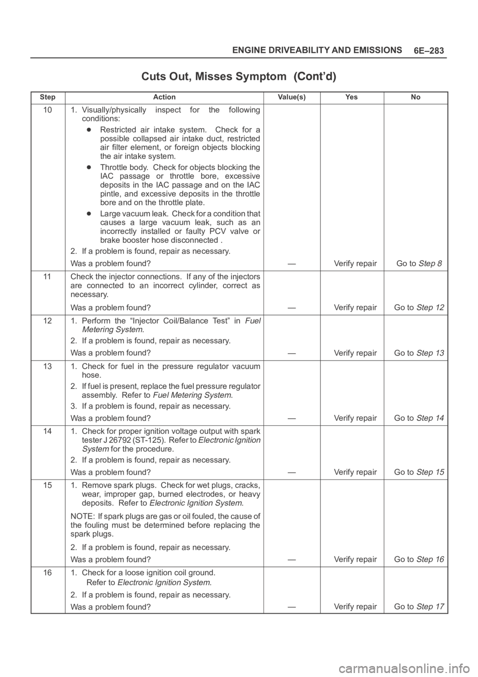
Cuts Out, Misses Symptom
StepNo Ye s Va l u e ( s ) Action
101. Visually/physically inspect for the following
conditions:
Restricted air intake system. Check for a
possible collapsed air intake duct, restricted
air filter element, or foreign objects blocking
the air intake system.
Throttle body. Check for objects blocking the
IAC passage or throttle bore, excessive
deposits in the IAC passage and on the IAC
pintle, and excessive deposits in the throttle
bore and on the throttle plate.
Large vacuum leak. Check for a condition that
causes a large vacuum leak, such as an
incorrectly installed or faulty PCV valve or
brake booster hose disconnected .
2. If a problem is found, repair as necessary.
Was a problem found?
—Verify repairGo to Step 8
11Check the injector connections. If any of the injectors
are connected to an incorrect cylinder, correct as
necessary.
Was a problem found?
—Verify repairGo to Step 12
121. Perform the “Injector Coil/Balance Test” in Fuel
Metering System
.
2. If a problem is found, repair as necessary.
Was a problem found?
—Verify repairGo to Step 13
131. Check for fuel in the pressure regulator vacuum
hose.
2. If fuel is present, replace the fuel pressure regulator
assembly. Refer to
Fuel Metering System.
3. If a problem is found, repair as necessary.
Was a problem found?
—Verify repairGo to Step 14
141. Check for proper ignition voltage output with spark
tester J 26792 (ST-125). Refer to
Electronic Ignition
System
for the procedure.
2. If a problem is found, repair as necessary.
Was a problem found?
—Verify repairGo to Step 15
151. Remove spark plugs. Check for wet plugs, cracks,
wear, improper gap, burned electrodes, or heavy
deposits. Refer to
Electronic Ignition System.
NOTE: If spark plugs are gas or oil fouled, the cause of
the fouling must be determined before replacing the
spark plugs.
2. If a problem is found, repair as necessary.
Was a problem found?
—Verify repairGo to Step 16
161. Check for a loose ignition coil ground.
Refer to
Electronic Ignition System.
2. If a problem is found, repair as necessary.
Was a problem found?
—Verify repairGo to Step 17
Page 4960 of 6000
6E–303 ENGINE DRIVEABILITY AND EMISSIONS
4. Check the transfer case oil level. Add fluid if
necessary.
5. Connect the negative battery cable.
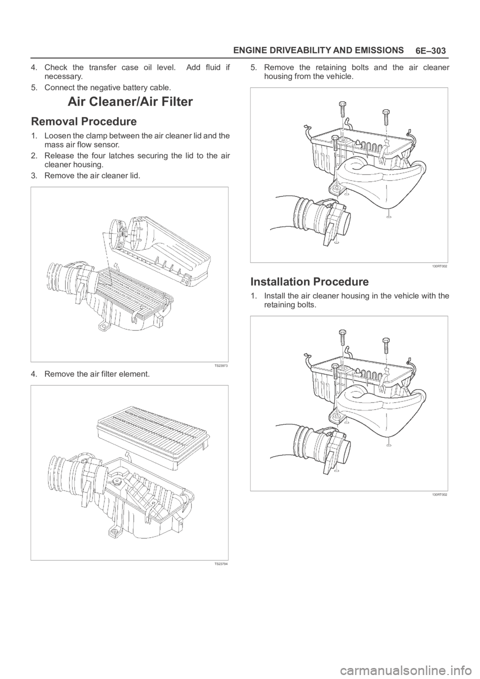
Air Cleaner/Air Filter
Removal Procedure
1. Loosen the clamp between the air cleaner lid and the
mass air flow sensor.
2. Release the four latches securing the lid to the air
cleaner housing.
3. Remove the air cleaner lid.
TS23973
4. Remove the air filter element.
TS23794
5. Remove the retaining bolts and the air cleaner
housing from the vehicle.
130RT002
Installation Procedure
1. Install the air cleaner housing in the vehicle with the
retaining bolts.
130RT002
Page 4961 of 6000
6E–304
ENGINE DRIVEABILITY AND EMISSIONS
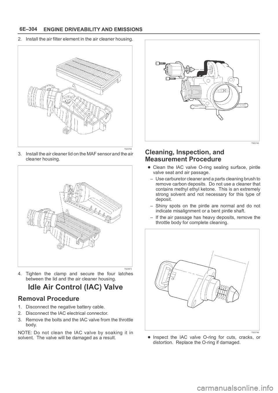
2. Install the air filter element in the air cleaner housing.
TS23794
3. Install the air cleaner lid on the MAF sensor and the air
cleaner housing.
TS23973
4. Tighten the clamp and secure the four latches
between the lid and the air cleaner housing.
Idle Air Control (IAC) Valve
Removal Procedure
1. Disconnect the negative battery cable.
2. Disconnect the IAC electrical connector.
3. Remove the bolts and the IAC valve from the throttle
body.
NOTE: Do not clean the IAC valve by soaking it in
solvent. The valve will be damaged as a result.
TS23745
Cleaning, Inspection, and
Measurement Procedure
Clean the IAC valve O-ring sealing surface, pintle
valve seat and air passage.
– Use carburetor cleaner and a parts cleaning brush to
remove carbon deposits. Do not use a cleaner that
contains methyl ethyl ketone. This is an extremely
strong solvent and not necessary for this type of
deposit.
– Shiny spots on the pintle are normal and do not
indicate misalignment or a bent pintle shaft.
– If the air passage has heavy deposits, remove the
throttle body for complete cleaning.
TS23746
Inspect the IAC valve O-ring for cuts, cracks, or
distortion. Replace the O-ring if damaged.
Page 4998 of 6000
6E–341 ENGINE DRIVEABILITY AND EMISSIONS
this is done, if the problem still exists, it may be diagnosed
in the normal manner.
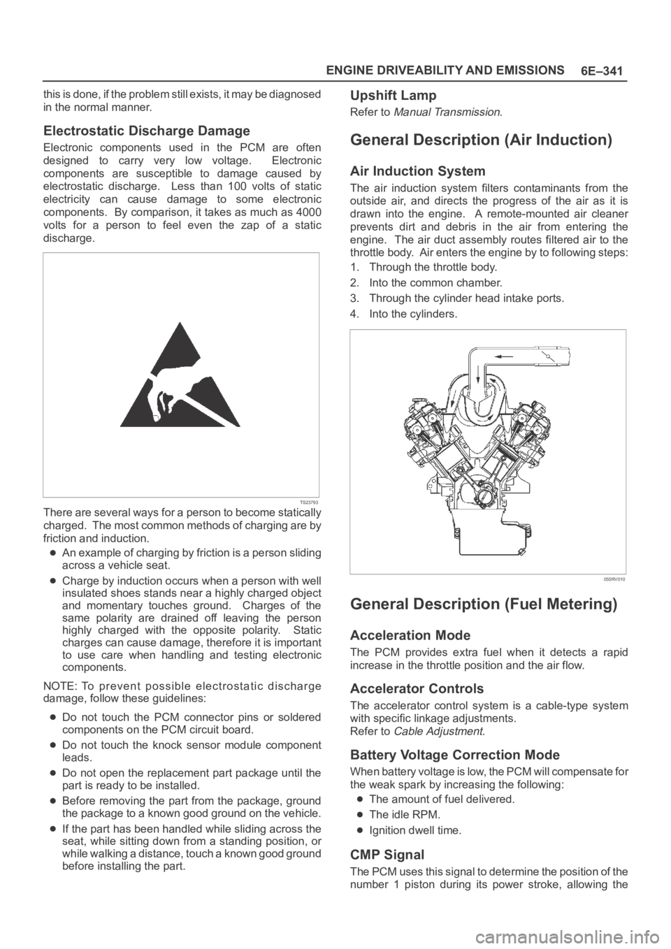
Electrostatic Discharge Damage
Electronic components used in the PCM are often
designed to carry very low voltage. Electronic
components are susceptible to damage caused by
electrostatic discharge. Less than 100 volts of static
electricity can cause damage to some electronic
components. By comparison, it takes as much as 4000
volts for a person to feel even the zap of a static
discharge.
TS23793
There are several ways for a person to become statically
charged. The most common methods of charging are by
friction and induction.
An example of charging by friction is a person sliding
across a vehicle seat.
Charge by induction occurs when a person with well
insulated shoes stands near a highly charged object
and momentary touches ground. Charges of the
same polarity are drained off leaving the person
highly charged with the opposite polarity. Static
charges can cause damage, therefore it is important
to use care when handling and testing electronic
components.
NOTE: To prevent possible electrostatic discharge
damage, follow these guidelines:
Do not touch the PCM connector pins or soldered
components on the PCM circuit board.
Do not touch the knock sensor module component
leads.
Do not open the replacement part package until the
part is ready to be installed.
Before removing the part from the package, ground
the package to a known good ground on the vehicle.
If the part has been handled while sliding across the
seat, while sitting down from a standing position, or
while walking a distance, touch a known good ground
before installing the part.
Upshift Lamp
Refer to Manual Transmission.
General Description (Air Induction)
Air Induction System
The air induction system filters contaminants from the
outside air, and directs the progress of the air as it is
drawn into the engine. A remote-mounted air cleaner
prevents dirt and debris in the air from entering the
engine. The air duct assembly routes filtered air to the
throttle body. Air enters the engine by to following steps:
1. Through the throttle body.
2. Into the common chamber.
3. Through the cylinder head intake ports.
4. Into the cylinders.
055RV010
General Description (Fuel Metering)
Acceleration Mode
The PCM provides extra fuel when it detects a rapid
increase in the throttle position and the air flow.
Accelerator Controls
The accelerator control system is a cable-type system
with specific linkage adjustments.
Refer to
Cable Adjustment.
Battery Voltage Correction Mode
When battery voltage is low, the PCM will compensate for
the weak spark by increasing the following:
The amount of fuel delivered.
The idle RPM.
Ignition dwell time.
CMP Signal
The PCM uses this signal to determine the position of the
number 1 piston during its power stroke, allowing the
Page 4999 of 6000

6E–342
ENGINE DRIVEABILITY AND EMISSIONS
PCM to calculate true sequential multiport fuel injection
(SFI). Loss of this signal will set a DTC P0341. If the CMP
signal is lost while the engine is running, the fuel injection
system will shift to a calculated sequential fuel injection
based on the last fuel injection pulse, and the engine will
continue to run. The engine can be restarted and will run
in the calculated sequential mode as long as the fault is
present, with a 1-in-6 chance of being correct.
Clear Flood Mode
Clear a flooded engine by pushing the accelerator pedal
down all the way. The PCM then de-energizes the fuel
injectors. The PCM holds the fuel injectors de-energized
as long as the throttle remains above 80% and the engine
speed is below 800 RPM. If the throttle position becomes
less than 80%, the PCM again begins to pulse the
injectors “ON” and “OFF,” allowing fuel into the cylinders.
Deceleration Mode
The PCM reduces the amount of fuel injected when it
detects a decrease in the throttle position and the air flow.
When deceleration is very fast, the PCM may cut off fuel
completely for short periods.
Engine Speed/Vehicle Speed/Fuel Disable
Mode
The PCM monitors engine speed. It turns off the fuel
injectors when the engine speed increase above 6400
RPM. The fuel injectors are turned back on when engine
speed decreases below 6150 RPM.
Fuel Cutoff Mode
No fuel is delivered by the fuel injectors when the ignition
is “OFF.” This prevents engine run-on. In addition, the
PCM suspends fuel delivery if no reference pulses are
detected (engine not running) to prevent engine flooding.
Fuel Injector
The sequential multiport fuel injection (SFI) fuel injector is
a solenoid-operated device controlled by the PCM. The
PCM energizes the solenoid, which opens a valve to allow
fuel delivery.
The fuel is injected under pressure in a conical spray
pattern at the opening of the intake valve. Excess fuel not
used by the injectors passes through the fuel pressure
regulator before being returned to the fuel tank.
A fuel injector which is stuck partly open will cause a loss
of fuel pressure after engine shut down, causing long
crank times.
0003
Fuel Metering System Components
The fuel metering system is made up of the following
parts:
The fuel injectors.
The throttle body.
The fuel rail.
The fuel pressure regulator.
The PCM.
The crankshaft position (CKP) sensor.
The camshaft position (CMP) sensor.
The idle air control (IAC) valve.
The fuel pump.
The fuel pump relay.
Basic System Operation
The fuel metering system starts with the fuel in the fuel
tank. An electric fuel pump, located in the fuel tank,
pumps fuel to the fuel rail through an in-line fuel filter. The
pump is designed to provide fuel at a pressure above the
pressure needed by the injectors. A fuel pressure
regulator in the fuel rail keeps fuel available to the fuel
injectors at a constant pressure. A return line delivers
unused fuel back to the fuel tank. Refer to
Section 6C f o r
further information on the fuel tank, line filter, and fuel
pipes.
Fuel Metering System Purpose
The basic function of the air/fuel metering system is to
control the air/fuel delivery to the engine. Fuel is delivered
to the engine by individual fuel injectors mounted in the
intake manifold near each intake valve.
The main control sensor is the heated oxygen sensor
(HO2S) located in the exhaust system. The HO2S tells
the PCM how much oxygen is in the exhaust gas. The
PCM changes the air/fuel ratio to the engine by controlling
the amount of time that fuel injector is “ON.” The best
mixture to minimize exhaust emissions is 14.7 parts of air
to 1 part of gasoline by weight, which allows the catalytic
converter to operate most efficiently. Because of the
Page 5020 of 6000
6G–1 ENGINE LUBRICATION
ENGINE
ENGINE LUBRICATION
CONTENTS
Service Precaution 6G–1. . . . . . . . . . . . . . . . . . . . . .
General Description 6G–2. . . . . . . . . . . . . . . . . . . . .
Oil Pump 6G–3. . . . . . . . . . . . . . . . . . . . . . . . . . . . . . .
Oil Pump and Associated Parts 6G–3. . . . . . . . . .
Oil Pump and Associated Parts 6G–3. . . . . . . . . .
Inspection and Repair 6G–4. . . . . . . . . . . . . . . . . .
Reassembly 6G–5. . . . . . . . . . . . . . . . . . . . . . . . . .
Oil Pan and Crankcase 6G–7. . . . . . . . . . . . . . . . . .
Removal 6G–7. . . . . . . . . . . . . . . . . . . . . . . . . . . . .
Installation 6G–7. . . . . . . . . . . . . . . . . . . . . . . . . . . .
Oil Pump 6G–10. . . . . . . . . . . . . . . . . . . . . . . . . . . . . . . Removal 6G–10. . . . . . . . . . . . . . . . . . . . . . . . . . . . .
Installation 6G–10. . . . . . . . . . . . . . . . . . . . . . . . . . . .
Oil Pump Oil Seal 6G–12. . . . . . . . . . . . . . . . . . . . . . .
Removal 6G–12. . . . . . . . . . . . . . . . . . . . . . . . . . . . .
Installation 6G–12. . . . . . . . . . . . . . . . . . . . . . . . . . . .
Oil Filter 6G–13. . . . . . . . . . . . . . . . . . . . . . . . . . . . . . . .
Removal 6G–13. . . . . . . . . . . . . . . . . . . . . . . . . . . . .
Installation 6G–13. . . . . . . . . . . . . . . . . . . . . . . . . . . .
Main Data and Specification 6G–14. . . . . . . . . . . . . .
Special Tool 6G–15. . . . . . . . . . . . . . . . . . . . . . . . . . . .
Service Precaution
WARNING: IF SO EQUIPPED WITH A
SUPPLEMENTAL RESTRAINT SYSTEM (SRS),
REFER TO THE SRS COMPONENT AND WIRING
LOCATION VIEW IN ORDER TO DETERMINE
WHETHER YOU ARE PERFORMING SERVICE ON OR
NEAR THE SRS COMPONENTS OR THE SRS
WIRING. WHEN YOU ARE PERFORMING SERVICE
ON OR NEAR THE SRS COMPONENTS OR THE SRS
WIRING, REFER TO THE SRS SERVICE
INFORMATION. FAILURE TO FOLLOW WARNINGS
COULD RESULT IN POSSIBLE AIR BAG
DEPLOYMENT, PERSONAL INJURY, OR
OTHERWISE UNNEEDED SRS SYSTEM REPAIRS.
CAUTION: Always use the correct fastener in the
proper location. When you replace a fastener, use
ONLY the exact part number for that application.
ISUZU will call out those fasteners that require a
replacement after removal. ISUZU will also call out
the fasteners that require thread lockers or thread
sealant. UNLESS OTHERWISE SPECIFIED, do not
use supplemental coatings (Paints, greases, or other
corrosion inhibitors) on threaded fasteners or
fastener joint interfaces. Generally, such coatings
adversely affect the fastener torque and the joint
clamping force, and may damage the fastener. When
you install fasteners, use the correct tightening
sequence and specifications. Following these
instructions can help you avoid damage to parts and
systems.