1998 OPEL FRONTERA air filter
[x] Cancel search: air filterPage 2121 of 6000
6E–228
4JX1–TC ENGINE DRIVEABILITY AND EMISSIONS
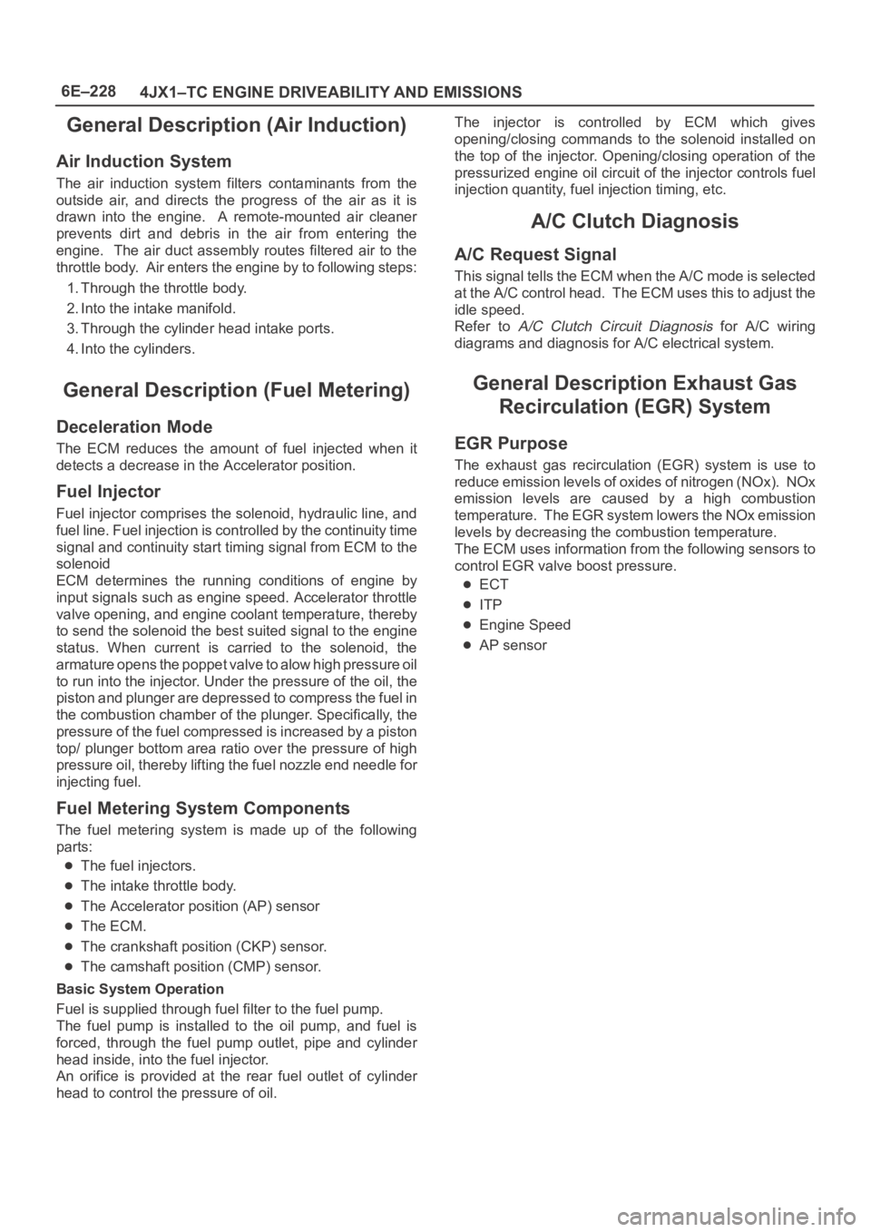
General Description (Air Induction)
Air Induction System
The air induction system filters contaminants from the
outside air, and directs the progress of the air as it is
drawn into the engine. A remote-mounted air cleaner
prevents dirt and debris in the air from entering the
engine. The air duct assembly routes filtered air to the
throttle body. Air enters the engine by to following steps:
1. Through the throttle body.
2. Into the intake manifold.
3. Through the cylinder head intake ports.
4. Into the cylinders.
General Description (Fuel Metering)
Deceleration Mode
The ECM reduces the amount of fuel injected when it
detects a decrease in the Accelerator position.
Fuel Injector
Fuel injector comprises the solenoid, hydraulic line, and
fuel line. Fuel injection is controlled by the continuity time
signal and continuity start timing signal from ECM to the
solenoid
ECM determines the running conditions of engine by
input signals such as engine speed. Accelerator throttle
valve opening, and engine coolant temperature, thereby
to send the solenoid the best suited signal to the engine
status. When current is carried to the solenoid, the
armature opens the poppet valve to alow high pressure oil
to run into the injector. Under the pressure of the oil, the
piston and plunger are depressed to compress the fuel in
the combustion chamber of the plunger. Specifically, the
pressure of the fuel compressed is increased by a piston
top/ plunger bottom area ratio over the pressure of high
pressure oil, thereby lifting the fuel nozzle end needle for
injecting fuel.
Fuel Metering System Components
The fuel metering system is made up of the following
parts:
The fuel injectors.
The intake throttle body.
The Accelerator position (AP) sensor
The ECM.
The crankshaft position (CKP) sensor.
The camshaft position (CMP) sensor.
Basic System Operation
Fuel is supplied through fuel filter to the fuel pump.
The fuel pump is installed to the oil pump, and fuel is
forced, through the fuel pump outlet, pipe and cylinder
head inside, into the fuel injector.
An orifice is provided at the rear fuel outlet of cylinder
head to control the pressure of oil.The injector is controlled by ECM which gives
opening/closing commands to the solenoid installed on
the top of the injector. Opening/closing operation of the
pressurized engine oil circuit of the injector controls fuel
injection quantity, fuel injection timing, etc.
A/C Clutch Diagnosis
A/C Request Signal
This signal tells the ECM when the A/C mode is selected
at the A/C control head. The ECM uses this to adjust the
idle speed.
Refer to
A/C Clutch Circuit Diagnosis for A/C wiring
diagrams and diagnosis for A/C electrical system.
General Description Exhaust Gas
Recirculation (EGR) System
EGR Purpose
The exhaust gas recirculation (EGR) system is use to
reduce emission levels of oxides of nitrogen (NOx). NOx
emission levels are caused by a high combustion
temperature. The EGR system lowers the NOx emission
levels by decreasing the combustion temperature.
The ECM uses information from the following sensors to
control EGR valve boost pressure.
ECT
ITP
Engine Speed
AP sensor
Page 2137 of 6000
6G – 6 ENGINE LUBRICATION
OIL COOLER ASSEMBLY
REMOVAL
1. Disconnect battery ground cable.
2. Drain engine coolant.
3. Remove front exhaust pipe.
4. Remove heat protector.
5. Remove exhaust valve assembly.
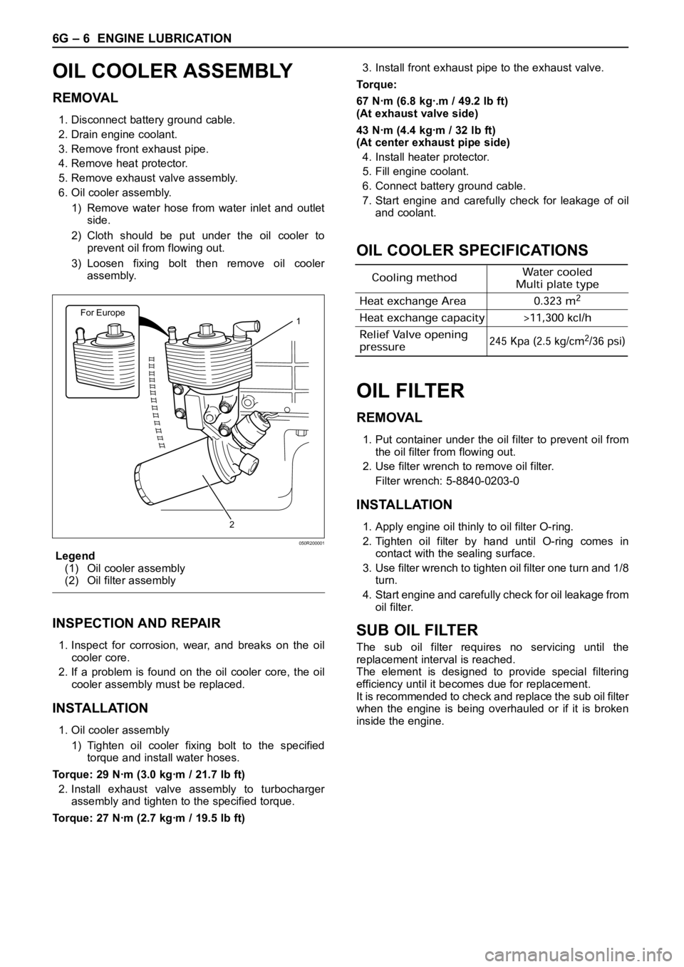
6. Oil cooler assembly.
1) Remove water hose from water inlet and outlet
side.
2) Cloth should be put under the oil cooler to
prevent oil from flowing out.
3) Loosen fixing bolt then remove oil cooler
assembly.
Legend
(1) Oil cooler assembly
(2) Oil filter assembly
INSPECTION AND REPAIR
1. Inspect for corrosion, wear, and breaks on the oil
cooler core.
2. If a problem is found on the oil cooler core, the oil
cooler assembly must be replaced.
INSTALLATION
1. Oil cooler assembly
1) Tighten oil cooler fixing bolt to the specified
torque and install water hoses.
Torque: 29 Nꞏm (3.0 kgꞏm / 21.7 lb ft)
2. Install exhaust valve assembly to turbocharger
assembly and tighten to the specified torque.
Torque: 27 Nꞏm (2.7 kgꞏm / 19.5 lb ft)3. Install front exhaust pipe to the exhaust valve.
Torque:
67 Nꞏm (6.8 kgꞏ.m / 49.2 lb ft)
(At exhaust valve side)
43 Nꞏm (4.4 kgꞏm / 32 lb ft)
(At center exhaust pipe side)
4. Install heater protector.
5. Fill engine coolant.
6. Connect battery ground cable.
7. Start engine and carefully check for leakage of oil
and coolant.
OIL COOLER SPECIFICATIONS
OIL FILTER
REMOVAL
1. Put container under the oil filter to prevent oil from
the oil filter from flowing out.
2. Use filter wrench to remove oil filter.
Filter wrench: 5-8840-0203-0
INSTALLATION
1. Apply engine oil thinly to oil filter O-ring.
2. Tighten oil filter by hand until O-ring comes in
contact with the sealing surface.
3. Use filter wrench to tighten oil filter one turn and 1/8
turn.
4. Start engine and carefully check for oil leakage from
oil filter.
SUB OIL FILTER
The sub oil filter requires no servicing until the
replacement interval is reached.
The element is designed to provide special filtering
efficiency until it becomes due for replacement.
It is recommended to check and replace the sub oil filter
when the engine is being overhauled or if it is broken
inside the engine.
For Europe1
2
050R200001
Page 2165 of 6000
7A–11 AUTOMATIC TRANSMISSION (4L30–E)
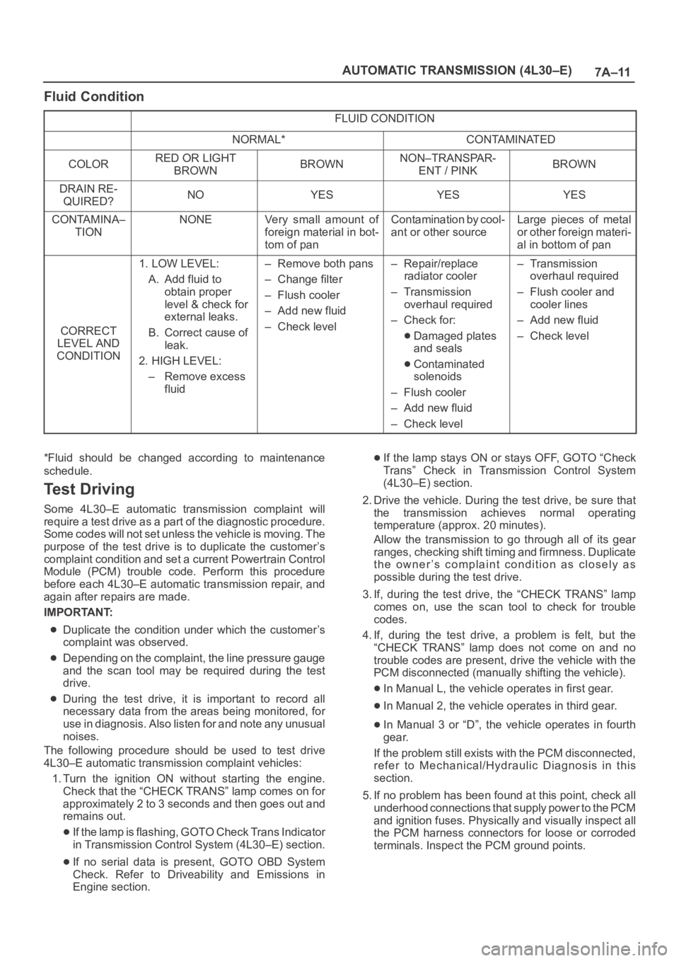
Fluid Condition
FLUID CONDITION
NORMAL*CONTAMINATED
COLORRED OR LIGHT
BROWNBROWNNON–TRANSPAR-
ENT / PINKBROWN
DRAIN RE-
QUIRED?NOYESYESYES
CONTAMINA–
TIONNONEVery small amount of
foreign material in bot-
tom of panContamination by cool-
ant or other sourceLarge pieces of metal
or other foreign materi-
al in bottom of pan
CORRECT
LEVEL AND
CONDITION
1. LOW LEVEL:
A. Add fluid to
obtain proper
level & check for
external leaks.
B. Correct cause of
leak.
2. HIGH LEVEL:
– Remove excess
fluid– Remove both pans
– Change filter
– Flush cooler
– Add new fluid
– Check level– Repair/replace
radiator cooler
–Transmission
overhaul required
– Check for:
Damaged plates
and seals
Contaminated
solenoids
– Flush cooler
– Add new fluid
– Check level
–Transmission
overhaul required
– Flush cooler and
cooler lines
– Add new fluid
– Check level
*Fluid should be changed according to maintenance
schedule.
Te s t D r i v i n g
Some 4L30–E automatic transmission complaint will
require a test drive as a part of the diagnostic procedure.
Some codes will not set unless the vehicle is moving. The
purpose of the test drive is to duplicate the customer’s
complaint condition and set a current Powertrain Control
Module (PCM) trouble code. Perform this procedure
before each 4L30–E automatic transmission repair, and
again after repairs are made.
IMPORTANT:
Duplicate the condition under which the customer’s
complaint was observed.
Depending on the complaint, the line pressure gauge
and the scan tool may be required during the test
drive.
During the test drive, it is important to record all
necessary data from the areas being monitored, for
use in diagnosis. Also listen for and note any unusual
noises.
The following procedure should be used to test drive
4L30–E automatic transmission complaint vehicles:
1. Turn the ignition ON without starting the engine.
Check that the “CHECK TRANS” lamp comes on for
approximately 2 to 3 seconds and then goes out and
remains out.
If the lamp is flashing, GOTO Check Trans Indicator
in Transmission Control System (4L30–E) section.
If no serial data is present, GOTO OBD System
Check. Refer to Driveability and Emissions in
Engine section.
If the lamp stays ON or stays OFF, GOTO “Check
Trans” Check in Transmission Control System
(4L30–E) section.
2. Drive the vehicle. During the test drive, be sure that
the transmission achieves normal operating
temperature (approx. 20 minutes).
Allow the transmission to go through all of its gear
ranges, checking shift timing and firmness. Duplicate
the owner’s complaint condition as closely as
possible during the test drive.
3. If, during the test drive, the “CHECK TRANS” lamp
comes on, use the scan tool to check for trouble
codes.
4. If, during the test drive, a problem is felt, but the
“CHECK TRANS” lamp does not come on and no
trouble codes are present, drive the vehicle with the
PCM disconnected (manually shifting the vehicle).
In Manual L, the vehicle operates in first gear.
In Manual 2, the vehicle operates in third gear.
In Manual 3 or “D”, the vehicle operates in fourth
gear.
If the problem still exists with the PCM disconnected,
refer to Mechanical/Hydraulic Diagnosis in this
section.
5. If no problem has been found at this point, check all
underhood connections that supply power to the PCM
and ignition fuses. Physically and visually inspect all
the PCM harness connectors for loose or corroded
terminals. Inspect the PCM ground points.
Page 2172 of 6000

7A–18
AUTOMATIC TRANSMISSION (4L30–E)
Chart 9c: Coastdown Harsh Shift Or Clunk At 3–2 Downshift
StepActionYe sNo
1Check line pressure. Refer to Line Pressure Test in this section.
Was line pressure normal?
Go to Step 2
Use Chart 15b:
Possible Causes
of High Line
Pressure in this
section
2Does DTC P1850 set?
Diagnose P1850
first
Replace band
apply solenoid
(PWM) (323)
Chart 10: Intermittent 4TH TO 2ND Gear Downshift At Steady Speed
StepActionYe sNo
1Check for consistent speed sensor reading with scan tool.
Was the reading correct?Replace mode
switch for
intermittent
contact.
Go to Step 2
21. Check for wiring harness damage or short to ground. If OK, go
to (2).
2. Check transmission speed sensor connections. If OK, go to
(3).
3. Replace transmission speed sensor.
Was the replacement complete?
—
Replace speed
sensor.
Chart 11: Engine Flare At Shifting During Turning Only (Usually With Warm Engine)
StepActionYe sNo
1Check for oil leaks at transmission.
Was the problem found?Replace
transmission oil
filter and gasket
—
Chart 12: Engine Flare During 1–2 Or 2–3 Shift
StepActionYe sNo
1Check line pressure. Refer to Line Pressure Test in this section.
Was line pressure normal?
Go to Step 2
Use Chart 15a:
Possible Causes
of Low Line
Pressure in this
section
21. Check for a stuck 1–2 accumulator valve (320).
2. Check for servo piston (106) leaks.
3. Check for a stuck band apply solenoid (323).
Was line pressure normal?
Repair or replace—
Page 2173 of 6000
7A–19 AUTOMATIC TRANSMISSION (4L30–E)
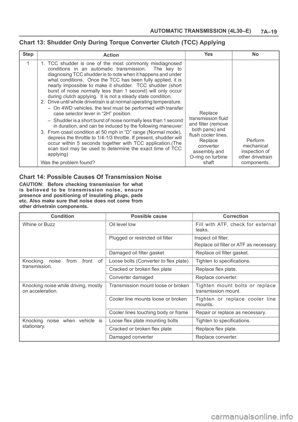
Chart 13: Shudder Only During Torque Converter Clutch (TCC) Applying
StepActionYe sNo
11. TCC shudder is one of the most commonly misdiagnosed
conditions in an automatic transmission. The key to
diagnosing TCC shudder is to note when it happens and under
what conditions. Once the TCC has been fully applied, it is
nearly impossible to make it shudder. TCC shudder (short
burst of noise normally less than 1 second) will only occur
during clutch applying. It is not a steady state condition.
2. Drive until whole drivetrain is at normal operating temperature.
– On 4WD vehicles, the test must be performed with transfer
case selector lever in “2H” position.
– Shudder is a short burst of noise normally less than 1 second
in duration, and can be induced by the following maneuver:
3. From coast condition at 50 mph in “D” range (Normal mode),
depress the throttle to 1/4-1/3 throttle. If present, shudder will
occur within 5 seconds together with TCC application.(The
scan tool may be used to determine the exact time of TCC
applying)
Was the problem found?
Replace
transmission fluid
and filter (remove
both pans) and
flush cooler lines.
Replace
converter
assembly and
O-ring on turbine
shaft
Perform
mechanical
inspection of
other drivetrain
components.
Chart 14: Possible Causes Of Transmission Noise
CAUTION: Before checking transmission for what
is believed to be transmission noise, ensure
presence and positioning of insulating plugs, pads
etc. Also make sure that noise does not come from
other drivetrain components.
Condition
Possible causeCorrection
Whine or BuzzOil level lowFill with ATF, check for external
leaks.
Plugged or restricted oil filterInspect oil filter.
Replace oil filter or ATF as necessary.
Damaged oil filter gasketReplace oil filter gasket.
Knocking noise from front of
transmission
Loose bolts (Converter to flex plate)Tighten to specifications.
transmission.Cracked or broken flex plateReplace flex plate.
Converter damagedReplace converter.
Knocking noise while driving, mostly
on acceleration.Transmission mount loose or brokenTighten mount bolts or replace
transmission mount.
Cooler line mounts loose or brokenTighten or replace cooler line
mounts.
Cooler lines touching body or frameRepair or replace as necessary.
Knocking noise when vehicle is
stationary
Loose flex plate mounting boltsTighten to specifications.
stationary.Cracked or broken flex plateReplace flex plate.
Damaged converterReplace converter.
Page 4049 of 6000
4B1–4
DRIVE LINE CONTROL SYSTEM (SHIFT ON THE FLY)
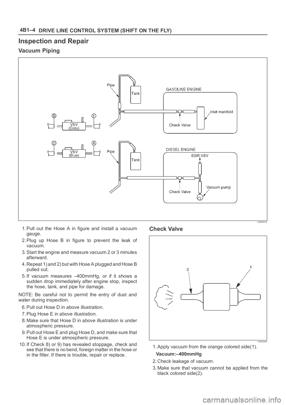
Inspection and Repair
Va c u u m P i p i n g
C04RW016
1. Pull out the Hose A in figure and install a vacuum
gauge.
2. Plug up Hose B in figure to prevent the leak of
vacuum.
3. Start the engine and measure vacuum 2 or 3 minutes
afterward.
4. Repeat 1) and 2) but with Hose A plugged and Hose B
pulled out.
5. If vacuum measures –400mmHg, or if it shows a
sudden drop immediately after engine stop, inspect
the hose, tank, and pipe for damage.
NOTE: Be careful not to permit the entry of dust and
water during inspection.
6. Pull out Hose D in above illustration.
7. Plug Hose E in above illustration.
8. Make sure that Hose D in above illustration is under
atmospheric pressure.
9. Pull out Hose E and plug Hose D, and make sure that
Hose E is under atmospheric pressure.
10. If Check 8) or 9) has revealed stoppage, check and
see that there is no bend, foreign matter in the hose or
in the filter. If there is trouble, repair or replace.Check Valve
C04RS004
1. Apply vacuum from the orange colored side(1).
Vacuum:–400mmHg
2. Check leakage of vacuum.
3. Make sure that vacuum cannot be applied from the
black colored side(2).
Page 4078 of 6000
4B1–33 DRIVE LINE CONTROL SYSTEM (SHIFT ON THE FLY)
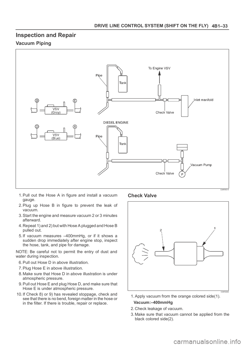
Inspection and Repair
Va c u u m P i p i n g
C04RW014
1. Pull out the Hose A in figure and install a vacuum
gauge.
2. Plug up Hose B in figure to prevent the leak of
vacuum.
3. Start the engine and measure vacuum 2 or 3 minutes
afterward.
4. Repeat 1) and 2) but with Hose A plugged and Hose B
pulled out.
5. If vacuum measures –400mmHg, or if it shows a
sudden drop immediately after engine stop, inspect
the hose, tank, and pipe for damage.
NOTE: Be careful not to permit the entry of dust and
water during inspection.
6. Pull out Hose D in above illustration.
7. Plug Hose E in above illustration.
8. Make sure that Hose D in above illustration is under
atmospheric pressure.
9. Pull out Hose E and plug Hose D, and make sure that
Hose E is under atmospheric pressure.
10. If Check 8) or 9) has revealed stoppage, check and
see that there is no bend, foreign matter in the hose or
in the filter. If there is trouble, repair or replace.Check Valve
C04RS004
1. Apply vacuum from the orange colored side(1).
Vacuum:–400mmHg
2. Check leakage of vacuum.
3. Make sure that vacuum cannot be applied from the
black colored side(2).
Page 4499 of 6000
6A–3
ENGINE MECHANICAL
General Description
Engine Cleanliness And Care
An automobile engine is a combination of many
machined, honed, polished and lapped surfaces with
tolerances that are measured in the thousandths of a
millimeter (ten thousandths of an inch). Accordingly,
when any internal engine parts are serviced, care and
cleanliness are important. Throughout this section, it
should be understood that proper cleaning and protection
of machined surfaces and friction areas is part of the
repair procedure. This is considered standard shop
practice even if not specifically stated.
A liberal coating of engine oil should be applied to all
friction areas during assembly to protect and lubricate
the surfaces on initial operation.
Whenever valve train components, pistons, piston
rings, connecting rods, rod bearings, and crankshaft
journal bearings are removed for service, they should
be retained in order.
At the time of installation, they should be installed in
the same locations and with the same mating
surfaces as when removed.
Battery cables should be disconnected before any
major work is performed on the engine. Failure to
disconnect cables may result in damage to wire
harness or other electrical parts.
The six cylinders of this engine are identified by
numbers; Right side cylinders 1, 3 and 5, Left side
cylinders 2, 4 and 6, as counted from crankshaft
pulley side to flywheel side.
General Information on Engine Service
The following information on engine service should be
noted carefully, as it is important in preventing damage
and contributing to reliable engine performance:
When raising or supporting the engine for any reason,
do not use a jack under the oil pan. Due to the small
clearance between the oil pan and the oil pump
strainer, jacking against the oil pan may cause
damage to the oil pick–up unit.
The 12–volt electrical system is capable of damaging
circuits. When performing any work where electrical
terminals could possibly be grounded, the ground
cable of the battery should be disconnected at the
battery.
Any time the intake air duct or air cleaner is removed,
the intake opening should be covered. This will
protect against accidental entrance of foreign
material into the cylinder which could cause extensive
damage when the engine is started.
Cylinder Block
The cylinder block is made of aluminum die–cast casting
for 75
V–type six cylinders. It has a rear plate integrated
structure and employs a deep skint. The cylinder liner is
cast and the liner inner diameter and crankshaft journal
diameter are classified into grades. The crankshaft is
supported by four bearings of which width of No.3 bearing
on the body side is different in order to support the thrust
bearing. The bearing cap is made of nodular cast iron and
each bearing cap uses four bolts and two side bolts.
Cylinder Head
The cylinder head, made of aluminum alloy casting
employs a pent–roof type combustion chamber with a
spark plug in the center. The intake and exhaust valves
are placed in V–type design. The ports are cross–flow
type.
Va l v e Tr a i n
Intake and exhaust camshaft on the both side of banks
are driven through an camshaft drive gear by timing belt.
The valves are operated by the camshaft and the valve
clearance is adjusted to select suitable thickness shim.
Intake Manifold
The intake manifold system is composed of the aluminum
cast common chamber and intake manifold attached with
six fuel injectors.
Exhaust Manifold
The exhaust manifold is made of nodular cast iron.
Pistons and Connecting Rods
Aluminum pistons are used after selecting the grade that
meets the cylinder bore diameter. Each piston has two
compression rings and one oil ring. The piston pin is made
of chromium steel is offset 1mm toward the thrust side,
and the thrust pressure of piston to the cylinder wall varies
gradually as the piston travels. The connecting rods are
made of forged steel. The connecting rod bearings are
graded for correct seze selection.
Crankshaft and Bearings
The crankshaft is made of Ductile cast–iron. Pins and
journals are graded for correct size selection for their
bearing.
Engine Lubrication
The oil discharged by a trochoid–type oil pump driven by
the crankshaft is fed through full–flow oil filter and to the oil
gallery provided under the crankshaft bearing cap. The oil
is then led to the crankshaft journals and cylinder head.
The crank pins are lubricated with oil from crankshaft
journals through oil holes. Also, an oil jet is fed to each
cylinder from crankshaft juornals on the connecting rod
for piston cleaning. The oil pan flange is dealed with liquid
packing only; do not deform or damage the flange surface
during removal or installation.