1998 OPEL FRONTERA air filter
[x] Cancel search: air filterPage 5612 of 6000
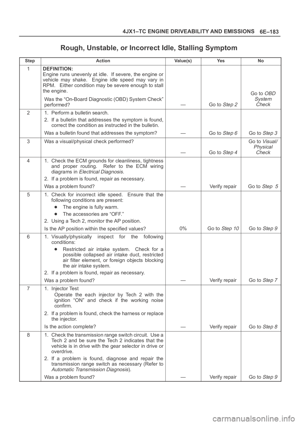
6E–183 4JX1–TC ENGINE DRIVEABILITY AND EMISSIONS
Rough, Unstable, or Incorrect Idle, Stalling Symptom
StepActionVa l u e ( s )Ye sNo
1DEFINITION:
Engine runs unevenly at idle. If severe, the engine or
vehicle may shake. Engine idle speed may vary in
RPM. Either condition may be severe enough to stall
the engine.
Was the “On-Board Diagnostic (OBD) System Check”
performed?
—Go to Step 2
Go to OBD
System
Check
21. Perform a bulletin search.
2. If a bulletin that addresses the symptom is found,
correct the condition as instructed in the bulletin.
Was a bulletin found that addresses the symptom?
—Go to Step 6Go to Step 3
3Was a visual/physical check performed?
—Go to Step 4
Go to Visual/
Physical
Check
41. Check the ECM grounds for cleanliness, tightness
and proper routing. Refer to the ECM wiring
diagrams in
Electrical Diagnosis.
2. If a problem is found, repair as necessary.
Was a problem found?
—Verify repairGo to Step 5
51. Check for incorrect idle speed. Ensure that the
following conditions are present:
The engine is fully warm.
The accessories are “OFF.”
2. Using a Tech 2, monitor the AP position.
Is the AP position within the specified values?
0%Go to Step 10Go to Step 9
61. Visually/physically inspect for the following
conditions:
Restricted air intake system. Check for a
possible collapsed air intake duct, restricted
air filter element, or foreign objects blocking
the air intake system.
2. If a problem is found, repair as necessary.
Was a problem found?
—Verify repairGo to Step 7
71. Injector Test
Operate the each injector by Tech 2 with the
ignition “ON” and check if the working noise
confirm.
2. If a problem is found, check the harness or replace
the injector.
Is the action complete?
—Verify repairGo to Step 8
81. Check the transmission range switch circuit. Use a
Tech 2 and be sure the Tech 2 indicates that the
vehicle is in drive with the gear selector in drive or
overdrive.
2. If a problem is found, diagnose and repair the
transmission range switch as necessary (Refer to
Automatic Transmission Diagnosis).
Was a problem found?
—Verify repairGo to Step 9
Page 5614 of 6000
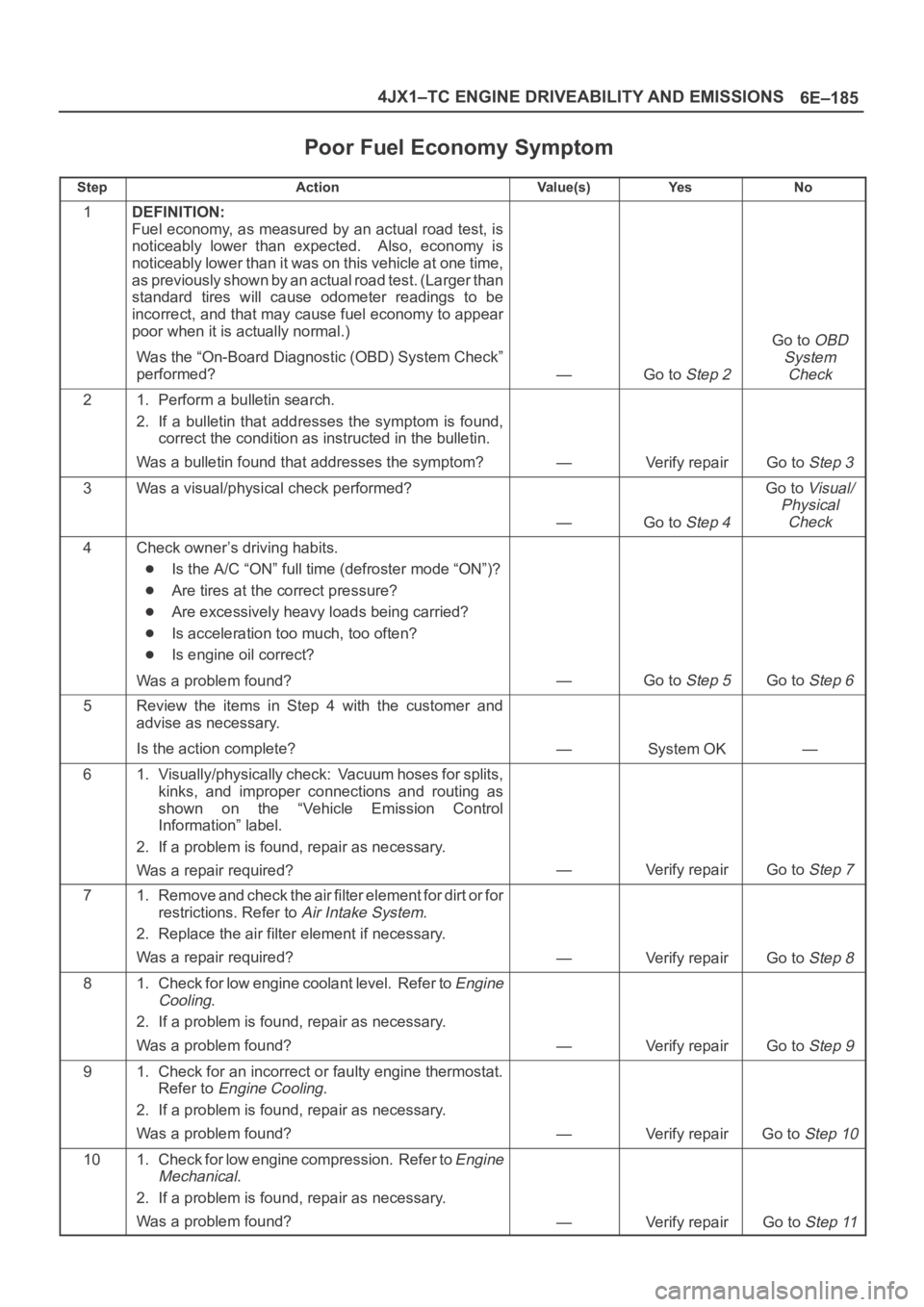
6E–185 4JX1–TC ENGINE DRIVEABILITY AND EMISSIONS
Poor Fuel Economy Symptom
StepActionVa l u e ( s )Ye sNo
1DEFINITION:
Fuel economy, as measured by an actual road test, is
noticeably lower than expected. Also, economy is
noticeably lower than it was on this vehicle at one time,
as previously shown by an actual road test. (Larger than
standard tires will cause odometer readings to be
incorrect, and that may cause fuel economy to appear
poor when it is actually normal.)
Was the “On-Board Diagnostic (OBD) System Check”
performed?
—Go to Step 2
Go to OBD
System
Check
21. Perform a bulletin search.
2. If a bulletin that addresses the symptom is found,
correct the condition as instructed in the bulletin.
Was a bulletin found that addresses the symptom?
—Verify repairGo to Step 3
3Was a visual/physical check performed?
—Go to Step 4
Go to Visual/
Physical
Check
4Check owner’s driving habits.
Is the A/C “ON” full time (defroster mode “ON”)?
Are tires at the correct pressure?
Are excessively heavy loads being carried?
Is acceleration too much, too often?
Is engine oil correct?
Was a problem found?
—Go to Step 5Go to Step 6
5Review the items in Step 4 with the customer and
advise as necessary.
Is the action complete?
—System OK—
61. Visually/physically check: Vacuum hoses for splits,
kinks, and improper connections and routing as
shown on the “Vehicle Emission Control
Information” label.
2. If a problem is found, repair as necessary.
Was a repair required?
—Verify repairGo to Step 7
71. Remove and check the air filter element for dirt or for
restrictions. Refer to
Air Intake System.
2. Replace the air filter element if necessary.
Was a repair required?
—Verify repairGo to Step 8
81. Check for low engine coolant level. Refer to Engine
Cooling
.
2. If a problem is found, repair as necessary.
Was a problem found?
—Verify repairGo to Step 9
91. Check for an incorrect or faulty engine thermostat.
Refer to
Engine Cooling.
2. If a problem is found, repair as necessary.
Was a problem found?
—Verify repairGo to Step 10
101. Check for low engine compression. Refer to Engine
Mechanical
.
2. If a problem is found, repair as necessary.
Was a problem found?
—Verify repairGo to Step 11
Page 5618 of 6000
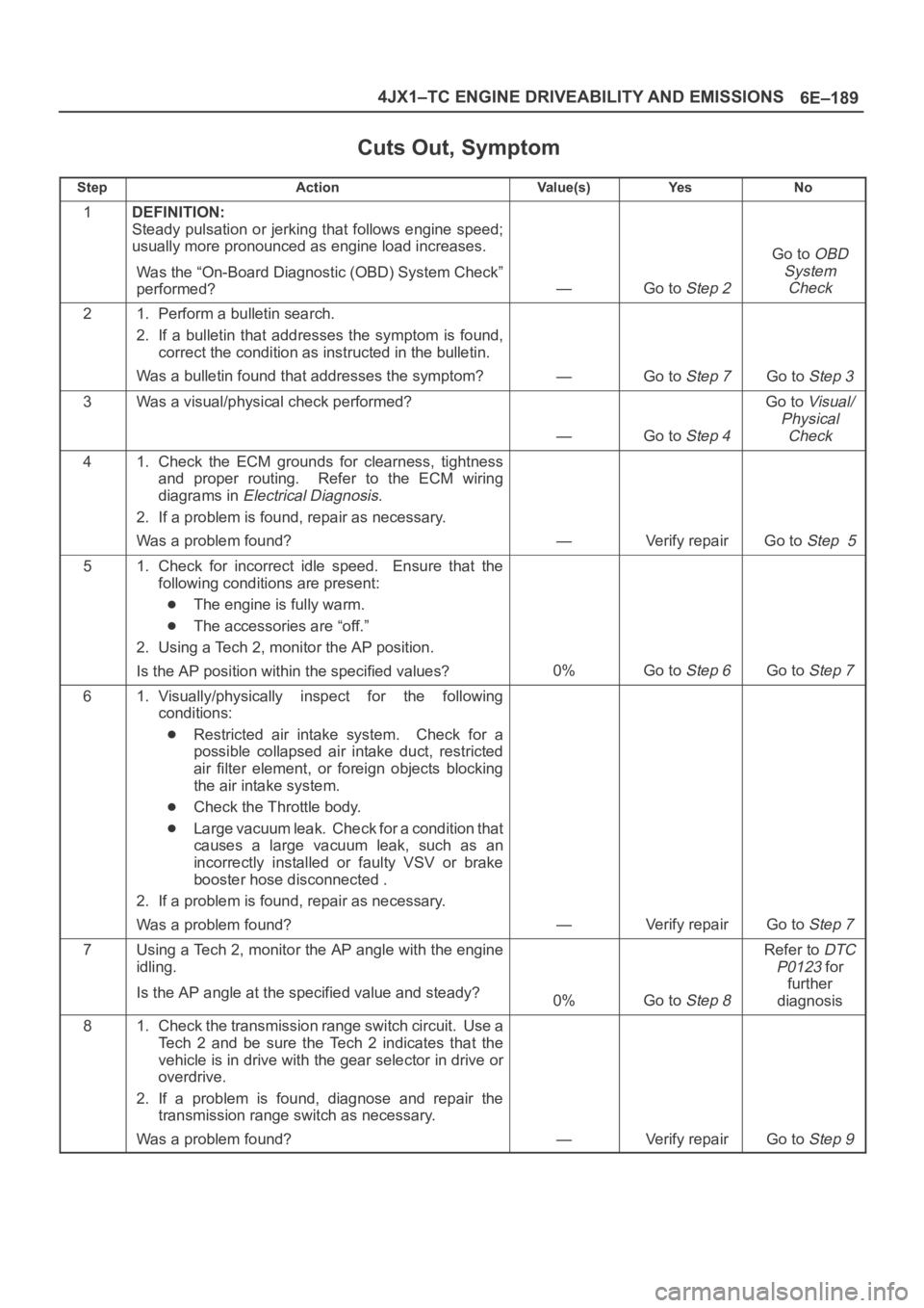
6E–189 4JX1–TC ENGINE DRIVEABILITY AND EMISSIONS
Cuts Out, Symptom
StepActionVa l u e ( s )Ye sNo
1DEFINITION:
Steady pulsation or jerking that follows engine speed;
usually more pronounced as engine load increases.
Was the “On-Board Diagnostic (OBD) System Check”
performed?
—Go to Step 2
Go to OBD
System
Check
21. Perform a bulletin search.
2. If a bulletin that addresses the symptom is found,
correct the condition as instructed in the bulletin.
Was a bulletin found that addresses the symptom?
—Go to Step 7Go to Step 3
3Was a visual/physical check performed?
—Go to Step 4
Go to Visual/
Physical
Check
41. Check the ECM grounds for clearness, tightness
and proper routing. Refer to the ECM wiring
diagrams in
Electrical Diagnosis.
2. If a problem is found, repair as necessary.
Was a problem found?
—Verify repairGo to Step 5
51. Check for incorrect idle speed. Ensure that the
following conditions are present:
The engine is fully warm.
The accessories are “off.”
2. Using a Tech 2, monitor the AP position.
Is the AP position within the specified values?
0%Go to Step 6Go to Step 7
61. Visually/physically inspect for the following
conditions:
Restricted air intake system. Check for a
possible collapsed air intake duct, restricted
air filter element, or foreign objects blocking
the air intake system.
Check the Throttle body.
Large vacuum leak. Check for a condition that
causes a large vacuum leak, such as an
incorrectly installed or faulty VSV or brake
booster hose disconnected .
2. If a problem is found, repair as necessary.
Was a problem found?
—Verify repairGo to Step 7
7Using a Tech 2, monitor the AP angle with the engine
idling.
Is the AP angle at the specified value and steady?
0%Go to Step 8
Refer to DTC
P0123
for
further
diagnosis
81. Check the transmission range switch circuit. Use a
Tech 2 and be sure the Tech 2 indicates that the
vehicle is in drive with the gear selector in drive or
overdrive.
2. If a problem is found, diagnose and repair the
transmission range switch as necessary.
Was a problem found?
—Verify repairGo to Step 9
Page 5621 of 6000
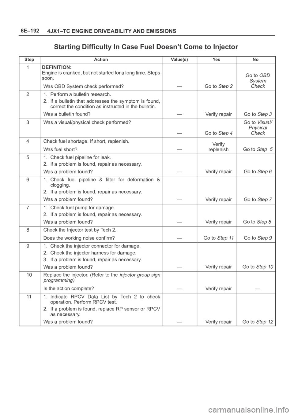
6E–192
4JX1–TC ENGINE DRIVEABILITY AND EMISSIONS
Starting Difficulty In Case Fuel Doesn’t Come to Injector
StepActionVa l u e ( s )Ye sNo
1DEFINITION:
Engine is cranked, but not started for a long time. Steps
soon.
Was OBD System check performed?
—Go to Step 2
Go to OBD
System
Check
21. Perform a bulletin research.
2. If a bulletin that addresses the symptom is found,
correct the condition as instructed in the bulletin.
Was a bulletin found?
—Verify repairGo to Step 3
3Was a visual/physical check performed?
—Go to Step 4
Go to Visual/
Physical
Check
4Check fuel shortage. If short, replenish.
Was fuel short?
—
Ve r i f y
replenish
Go to Step 5
51. Check fuel pipeline for leak.
2. If a problem is found, repair as necessary.
Was a problem found?
—Verify repairGo to Step 6
61. Check fuel pipeline & filter for deformation &
clogging.
2. If a problem is found, repair as necessary.
Was a problem found?
—Verify repairGo to Step 7
71. Check fuel pump for damage.
2. If a problem is found, repair as necessary.
Was a problem found?
—Verify repairGo to Step 8
8Check the Injector test by Tech 2.
Does the working noise confirm?
—Go to Step 11Go to Step 9
91. Check the injector connector for damage.
2. Check the injector harness for damage.
3. If a problem is found, repair as necessary.
Was a problem found?
—Verify repairGo to Step 10
10Replace the injector. (Refer to the injector group sign
programming)
Is the action complete?—Verify repair—
111. Indicate RPCV Data List by Tech 2 to check
operation. Perform RPCV test.
2. If a problem is found, replace RP sensor or RPCV
as necessary.
Was a problem found?
—Verify repairGo to Step 12
Page 5623 of 6000
6E–194
4JX1–TC ENGINE DRIVEABILITY AND EMISSIONS
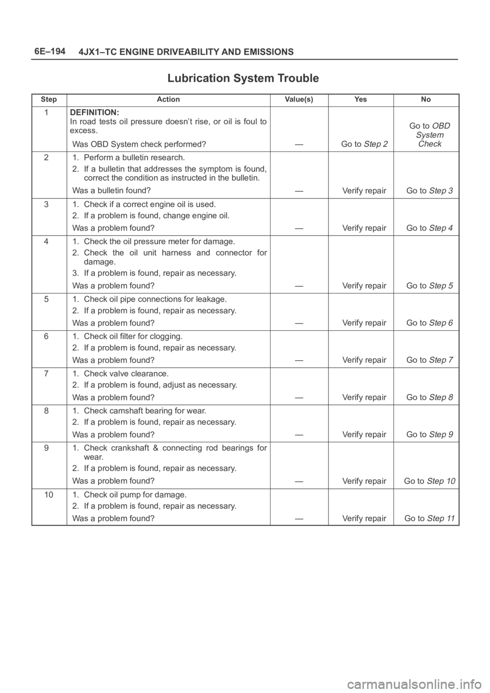
Lubrication System Trouble
StepActionVa l u e ( s )Ye sNo
1DEFINITION:
In road tests oil pressure doesn’t rise, or oil is foul to
excess.
Was OBD System check performed?
—Go to Step 2
Go to OBD
System
Check
21. Perform a bulletin research.
2. If a bulletin that addresses the symptom is found,
correct the condition as instructed in the bulletin.
Was a bulletin found?
—Verify repairGo to Step 3
31. Check if a correct engine oil is used.
2. If a problem is found, change engine oil.
Was a problem found?
—Verify repairGo to Step 4
41. Check the oil pressure meter for damage.
2. Check the oil unit harness and connector for
damage.
3. If a problem is found, repair as necessary.
Was a problem found?
—Verify repairGo to Step 5
51. Check oil pipe connections for leakage.
2. If a problem is found, repair as necessary.
Was a problem found?
—Verify repairGo to Step 6
61. Check oil filter for clogging.
2. If a problem is found, repair as necessary.
Was a problem found?
—Verify repairGo to Step 7
71. Check valve clearance.
2. If a problem is found, adjust as necessary.
Was a problem found?
—Verify repairGo to Step 8
81. Check camshaft bearing for wear.
2. If a problem is found, repair as necessary.
Was a problem found?
—Verify repairGo to Step 9
91. Check crankshaft & connecting rod bearings for
wear.
2. If a problem is found, repair as necessary.
Was a problem found?
—Verify repairGo to Step 10
101. Check oil pump for damage.
2. If a problem is found, repair as necessary.
Was a problem found?
—Verify repairGo to Step 11
Page 5640 of 6000
6E–211 4JX1–TC ENGINE DRIVEABILITY AND EMISSIONS
5. Connect the negative battery cable.
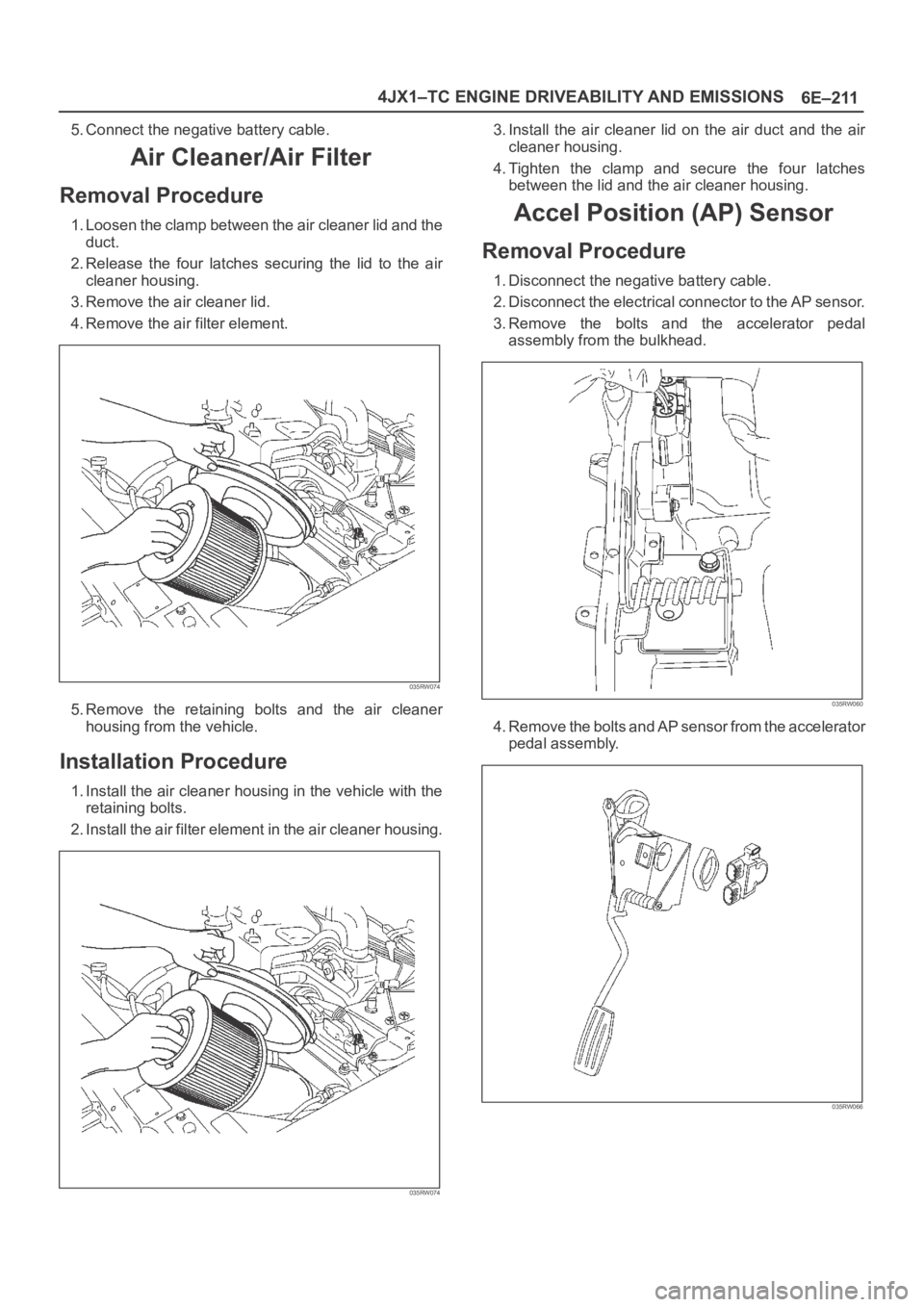
Air Cleaner/Air Filter
Removal Procedure
1. Loosen the clamp between the air cleaner lid and the
duct.
2. Release the four latches securing the lid to the air
cleaner housing.
3. Remove the air cleaner lid.
4. Remove the air filter element.
035RW074
5. Remove the retaining bolts and the air cleaner
housing from the vehicle.
Installation Procedure
1. Install the air cleaner housing in the vehicle with the
retaining bolts.
2. Install the air filter element in the air cleaner housing.
035RW074
3. Install the air cleaner lid on the air duct and the air
cleaner housing.
4. Tighten the clamp and secure the four latches
between the lid and the air cleaner housing.
Accel Position (AP) Sensor
Removal Procedure
1. Disconnect the negative battery cable.
2. Disconnect the electrical connector to the AP sensor.
3.Remove the bolts and the accelerator pedal
assembly from the bulkhead.
035RW060
4. Remove the bolts and AP sensor from the accelerator
pedal assembly.
035RW066
Page 5657 of 6000
6E–228
4JX1–TC ENGINE DRIVEABILITY AND EMISSIONS
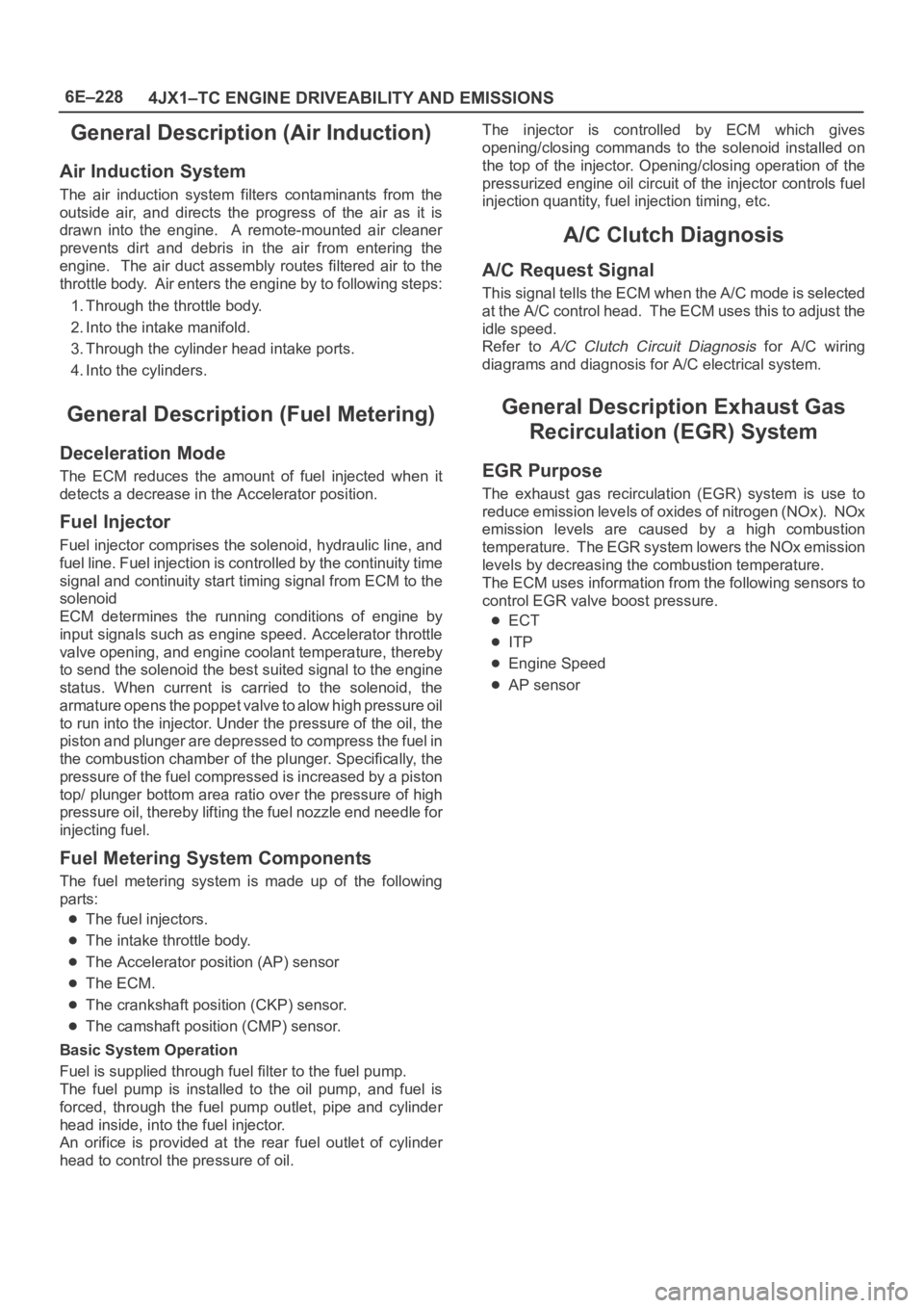
General Description (Air Induction)
Air Induction System
The air induction system filters contaminants from the
outside air, and directs the progress of the air as it is
drawn into the engine. A remote-mounted air cleaner
prevents dirt and debris in the air from entering the
engine. The air duct assembly routes filtered air to the
throttle body. Air enters the engine by to following steps:
1. Through the throttle body.
2. Into the intake manifold.
3. Through the cylinder head intake ports.
4. Into the cylinders.
General Description (Fuel Metering)
Deceleration Mode
The ECM reduces the amount of fuel injected when it
detects a decrease in the Accelerator position.
Fuel Injector
Fuel injector comprises the solenoid, hydraulic line, and
fuel line. Fuel injection is controlled by the continuity time
signal and continuity start timing signal from ECM to the
solenoid
ECM determines the running conditions of engine by
input signals such as engine speed. Accelerator throttle
valve opening, and engine coolant temperature, thereby
to send the solenoid the best suited signal to the engine
status. When current is carried to the solenoid, the
armature opens the poppet valve to alow high pressure oil
to run into the injector. Under the pressure of the oil, the
piston and plunger are depressed to compress the fuel in
the combustion chamber of the plunger. Specifically, the
pressure of the fuel compressed is increased by a piston
top/ plunger bottom area ratio over the pressure of high
pressure oil, thereby lifting the fuel nozzle end needle for
injecting fuel.
Fuel Metering System Components
The fuel metering system is made up of the following
parts:
The fuel injectors.
The intake throttle body.
The Accelerator position (AP) sensor
The ECM.
The crankshaft position (CKP) sensor.
The camshaft position (CMP) sensor.
Basic System Operation
Fuel is supplied through fuel filter to the fuel pump.
The fuel pump is installed to the oil pump, and fuel is
forced, through the fuel pump outlet, pipe and cylinder
head inside, into the fuel injector.
An orifice is provided at the rear fuel outlet of cylinder
head to control the pressure of oil.The injector is controlled by ECM which gives
opening/closing commands to the solenoid installed on
the top of the injector. Opening/closing operation of the
pressurized engine oil circuit of the injector controls fuel
injection quantity, fuel injection timing, etc.
A/C Clutch Diagnosis
A/C Request Signal
This signal tells the ECM when the A/C mode is selected
at the A/C control head. The ECM uses this to adjust the
idle speed.
Refer to
A/C Clutch Circuit Diagnosis for A/C wiring
diagrams and diagnosis for A/C electrical system.
General Description Exhaust Gas
Recirculation (EGR) System
EGR Purpose
The exhaust gas recirculation (EGR) system is use to
reduce emission levels of oxides of nitrogen (NOx). NOx
emission levels are caused by a high combustion
temperature. The EGR system lowers the NOx emission
levels by decreasing the combustion temperature.
The ECM uses information from the following sensors to
control EGR valve boost pressure.
ECT
ITP
Engine Speed
AP sensor
Page 5673 of 6000
6G – 6 ENGINE LUBRICATION
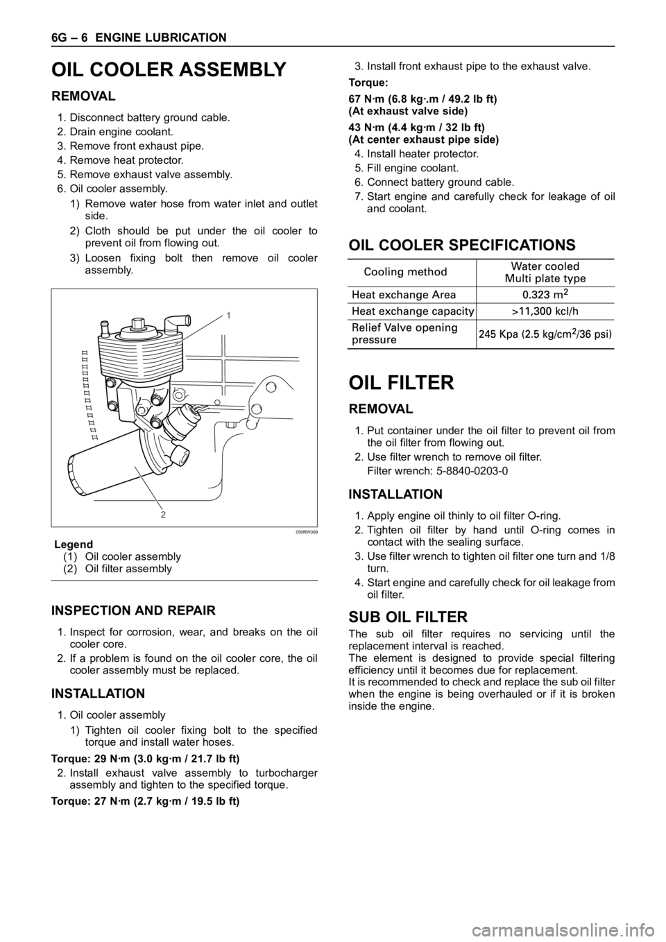
OIL COOLER ASSEMBLY
REMOVAL
1. Disconnect battery ground cable.
2. Drain engine coolant.
3. Remove front exhaust pipe.
4. Remove heat protector.
5. Remove exhaust valve assembly.
6. Oil cooler assembly.
1) Remove water hose from water inlet and outlet
side.
2) Cloth should be put under the oil cooler to
prevent oil from flowing out.
3) Loosen fixing bolt then remove oil cooler
assembly.
Legend
(1) Oil cooler assembly
(2) Oil filter assembly
INSPECTION AND REPAIR
1. Inspect for corrosion, wear, and breaks on the oil
cooler core.
2. If a problem is found on the oil cooler core, the oil
cooler assembly must be replaced.
INSTALLATION
1. Oil cooler assembly
1) Tighten oil cooler fixing bolt to the specified
torque and install water hoses.
Torque: 29 Nꞏm (3.0 kgꞏm / 21.7 lb ft)
2. Install exhaust valve assembly to turbocharger
assembly and tighten to the specified torque.
Torque: 27 Nꞏm (2.7 kgꞏm / 19.5 lb ft)3. Install front exhaust pipe to the exhaust valve.
To r q u e :
67 Nꞏm (6.8 kgꞏ.m / 49.2 lb ft)
(At exhaust valve side)
43 Nꞏm (4.4 kgꞏm / 32 lb ft)
(At center exhaust pipe side)
4. Install heater protector.
5. Fill engine coolant.
6. Connect battery ground cable.
7. Start engine and carefully check for leakage of oil
and coolant.
OIL COOLER SPECIFICATIONS
OIL FILTER
REMOVAL
1. Put container under the oil filter to prevent oil from
the oil filter from flowing out.
2. Use filter wrench to remove oil filter.
Filter wrench: 5-8840-0203-0
INSTALLATION
1. Apply engine oil thinly to oil filter O-ring.
2. Tighten oil filter by hand until O-ring comes in
contact with the sealing surface.
3. Use filter wrench to tighten oil filter one turn and 1/8
turn.
4. Start engine and carefully check for oil leakage from
oil filter.
SUB OIL FILTER
The sub oil filter requires no servicing until the
replacement interval is reached.
The element is designed to provide special filtering
efficiency until it becomes due for replacement.
It is recommended to check and replace the sub oil filter
when the engine is being overhauled or if it is broken
inside the engine.
1
2
050RW009