Page 5037 of 6000
6H–3 ENGINE SPEED CONTROL SYSTEM
Accelerator Pedal
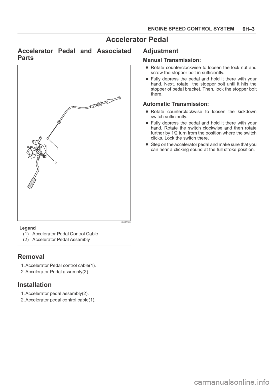
Accelerator Pedal and Associated
Parts
035RW028
Legend
(1) Accelerator Pedal Control Cable
(2) Accelerator Pedal Assembly
Removal
1. Accelerator Pedal control cable(1).
2. Accelerator Pedal assembly(2).
Installation
1. Accelerator pedal assembly(2).
2. Accelerator pedal control cable(1).
Adjustment
Manual Transmission:
Rotate counterclockwise to loosen the lock nut and
screw the stopper bolt in sufficiently.
Fully depress the pedal and hold it there with your
hand. Next, rotate the stopper bolt until it hits the
stopper of pedal bracket. Then, lock the stopper bolt
there.
Automatic Transmission:
Rotate counterclockwise to loosen the kickdown
switch sufficiently.
Fully depress the pedal and hold it there with your
hand. Rotate the switch clockwise and then rotate
further by 1/2 turn from the position where the switch
clicks. Lock the switch there.
Step on the accelerator pedal and make sure that you
can hear a clicking sound at the full stroke position.
Page 5039 of 6000
INDUCTION6J–1
ENGINE
INDUCTION
CONTENTS
Service Precaution 6J–1. . . . . . . . . . . . . . . . . . . . . .
Air Cleaner Element 6J–2. . . . . . . . . . . . . . . . . . . . .
Removal 6J–2. . . . . . . . . . . . . . . . . . . . . . . . . . . . .
Inspection 6J–2. . . . . . . . . . . . . . . . . . . . . . . . . . . .
Installation 6J–2. . . . . . . . . . . . . . . . . . . . . . . . . . . .
Service Precaution
WARNING: IF SO EQUIPPED WITH A
SUPPLEMENTAL RESTRAINT SYSTEM
(SRS),REFER TO THE SRS COMPONENT AND
WIRING LOCATION VIEW IN ORDER TO DETERMINE
WHETHER YOU ARE PERFORMING SERVICE ON OR
NEAR THE SRS COMPONENTS OR THE SRS
WIRING. WHEN YOU ARE PERFORMING SERVICE
ON OR NEAR THE SRS COMPONENTS OR THE SRS
WIRING, REFER TO THE SRS SERVICE
INFORMATION. FAILURE TO FOLLOW WARNINGS
COULD RESULT IN POSSIBLE AIR BAG
DEPLOYMENT, PERSONAL INJURY, OR
OTHERWISE UNNEEDED SRS SYSTEM REPAIRS.
CAUTION: Always use the correct fastener in the
proper location. When you replace a fastener, use
ONLY the exact part number for that application.
ISUZU will call out those fasteners that require a
replacement after removal. ISUZU will also call out
the fasteners that require thread lockers or thread
sealant. UNLESS OTHERWISE SPECIFIED, do not
use supplemental coatings (Paints, greases, or other
corrosion inhibitors) on threaded fasteners or
fastener joint interfaces. Generally, such coatings
adversely affect the fastener torque and the joint
clamping force, and may damage the fastener. When
you install fasteners, use the correct tightening
sequence and specifications. Following these
instructions can help you avoid damage to parts and
systems.
Page 5274 of 6000
ENGINE MECHANICAL 6A – 1
ENGINE
ENGINE MECHANICAL
CONTENTS
General Description . . . . . . . . . . . . . . . . . . . . 6A–2
Service Information . . . . . . . . . . . . . . . . . . . . 6A–3
Service Standard . . . . . . . . . . . . . . . . . . . . . . 6A–6
Servicing . . . . . . . . . . . . . . . . . . . . . . . . . . . . 6A–9
Tightening Torque . . . . . . . . . . . . . . . . . . . . . 6A–14
Special Tools . . . . . . . . . . . . . . . . . . . . . . . . . 6A–23
Engine Assembly . . . . . . . . . . . . . . . . . . . . . . 6A–26
Engine Mount (RH) . . . . . . . . . . . . . . . . . . . . 6A–28
Engine Mount (LH). . . . . . . . . . . . . . . . . . . . . 6A–29
Intercooler . . . . . . . . . . . . . . . . . . . . . . . . . . . 6A–30
Cylinder Head Cover . . . . . . . . . . . . . . . . . . . 6A–31
Intake Manifold . . . . . . . . . . . . . . . . . . . . . . . 6A–33
Exhaust Manifold . . . . . . . . . . . . . . . . . . . . . . 6A–34
Turbocharger . . . . . . . . . . . . . . . . . . . . . . . . . 6A–35Cylinder Head . . . . . . . . . . . . . . . . . . . . . . . . 6A–37
Cylinder Head Gasket . . . . . . . . . . . . . . . . . . 6A–39
Camshaft . . . . . . . . . . . . . . . . . . . . . . . . . . . . 6A–43
Timing Gear . . . . . . . . . . . . . . . . . . . . . . . . . . 6A–48
Valve Stem Seal, Valve Spring and Adjuster . . 6A–56
Valve Clearance Adjustment. . . . . . . . . . . . . . 6A–63
Oil Rail and Injector . . . . . . . . . . . . . . . . . . . . 6A–65
Crank Case . . . . . . . . . . . . . . . . . . . . . . . . . . 6A–68
Crankshaft . . . . . . . . . . . . . . . . . . . . . . . . . . . 6A–70
Piston and Connecting Rod . . . . . . . . . . . . . . 6A–80
Cylinder Block . . . . . . . . . . . . . . . . . . . . . . . . 6A–88
Oil Pump Assembly . . . . . . . . . . . . . . . . . . . . 6A–94
Oil Filter Cartridge . . . . . . . . . . . . . . . . . . . . . 6A–95
Oil Cooler . . . . . . . . . . . . . . . . . . . . . . . . . . . 6A–95
Page 5275 of 6000
6A – 2 ENGINE MECHANICAL
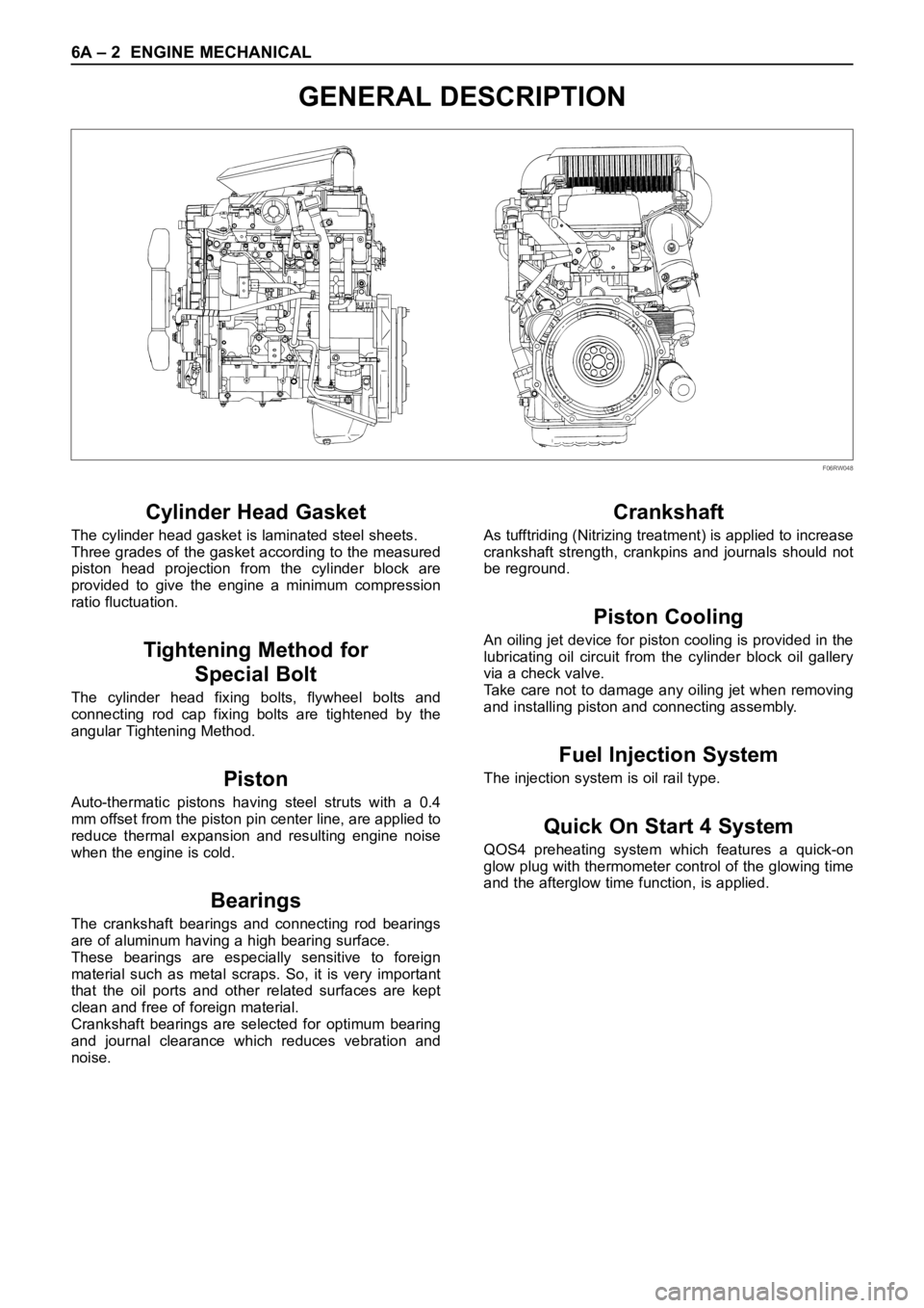
GENERAL DESCRIPTION
Cylinder Head Gasket
The cylinder head gasket is laminated steel sheets.
Three grades of the gasket according to the measured
piston head projection from the cylinder block are
provided to give the engine a minimum compression
ratio fluctuation.
Tightening Method for
Special Bolt
The cylinder head fixing bolts, flywheel bolts and
connecting rod cap fixing bolts are tightened by the
angular Tightening Method.
Piston
Auto-thermatic pistons having steel struts with a 0.4
mm offset from the piston pin center line, are applied to
reduce thermal expansion and resulting engine noise
when the engine is cold.
Bearings
The crankshaft bearings and connecting rod bearings
are of aluminum having a high bearing surface.
These bearings are especially sensitive to foreign
material such as metal scraps. So, it is very important
that the oil ports and other related surfaces are kept
clean and free of foreign material.
Crankshaft bearings are selected for optimum bearing
and journal clearance which reduces vebration and
noise.
Crankshaft
As tufftriding (Nitrizing treatment) is applied to increase
crankshaft strength, crankpins and journals should not
be reground.
Piston Cooling
An oiling jet device for piston cooling is provided in the
lubricating oil circuit from the cylinder block oil gallery
via a check valve.
Take care not to damage any oiling jet when removing
and installing piston and connecting assembly.
Fuel Injection System
The injection system is oil rail type.
Quick On Start 4 System
QOS4 preheating system which features a quick-on
glow plug with thermometer control of the glowing time
and the afterglow time function, is applied.
F06RW048
Page 5277 of 6000

6A – 4 ENGINE MECHANICAL
Engine Cooling
Starting System
Cooling system Coolant forced circulation
Radiator (2 tube in row) Tube type corrugated
Heat radiation capacity J/h (kcal/h) 318 x 10
6(76000)
Heat radiation area m
2(ft2) 15.63 (1.454)
Front area m
2(ft2) 0.309 (2.029)
Dry weight N (kg/lb) 83 (8.5/18.7)
Radiator cap
Valve opening pressure kPa (kg/cm
2psi) 93.3 – 122.7 (0.95 – 1.25/13.5 – 17.8)
Coolant capacity lit (Imp.qt./US qt.) M/T 2.5 (2.2/2.6) A/T 2.4 (2.1/2.5)
Coolant pump Centrifugal impeller type
Pulley ratio 1.2
Coolant total capacity lit (Imp.qt./US qt.) 9.3 (8.2/9.8)
Model HITACHI S14-0
Rating
Voltage V 12
Output kW 2.8
Time sec 30
Number of teeth of pinion 9
Rotating direction (as viewed from pinion) Clockwise
Weight (approx.) N(kg/lb) 49 (5.0/11)
No-load characteristics
Voltage/current V/A 11/160 or less
Speed rpm 4000 or more
Load characteristics
Voltage/current V/A 8.76/300
Torque Nꞏm(kgꞏm/lbꞏft) 7.4 (0.75/5.4) or more
Speed rpm 1700 or more
Locking characteristics
Voltage/current V/A 2.5/1100 or less
Torque Nꞏm(kgꞏm/lbꞏft) 18.6 (1.9/14) or more
Page 5278 of 6000
ENGINE MECHANICAL 6A – 5
Charging System
Model (HITACHI) LR160-734B LR170 – 760 LR190 – 750B
Rated voltage V 12
Rated output A 60 70 90
Rotation direction
Clockwise
(As viewed from pulled)
Pulley effective diameter mm (in) 60 (2.36) 69 (2.72)
Weight N (kg/lb) 41 (4.2/9.3) 52 (5.3/11.7)
Page 5281 of 6000
6A – 8 ENGINE MECHANICAL
Parts Items Service standard Service limit Remarks
Cylinder
Block—
95.421 – 95.450
(3.7567 – 3.7579)0.20 (0.0079) Warpage
(Upper surface of the cylinder block)
Cylinder bore diameter
Parts Items Service standard Service limit Remarks
Thermostat
Radiator cap83 – 87°C
(181 – 189°F)
More than 9.5 (0.374)
at 100°C (212°F)
88.2 – 117.6 kPa
(12.8 –17.0 psi) Valve opening temperature
Valve full open temperature and lift
Valve opening pressure
Engine Coolingmm (in) mm (in)
Page 5282 of 6000
ENGINE MECHANICAL 6A – 9
SERVICING
Servicing refers to general maintenance procedures to
be performed by qualified service personnel.
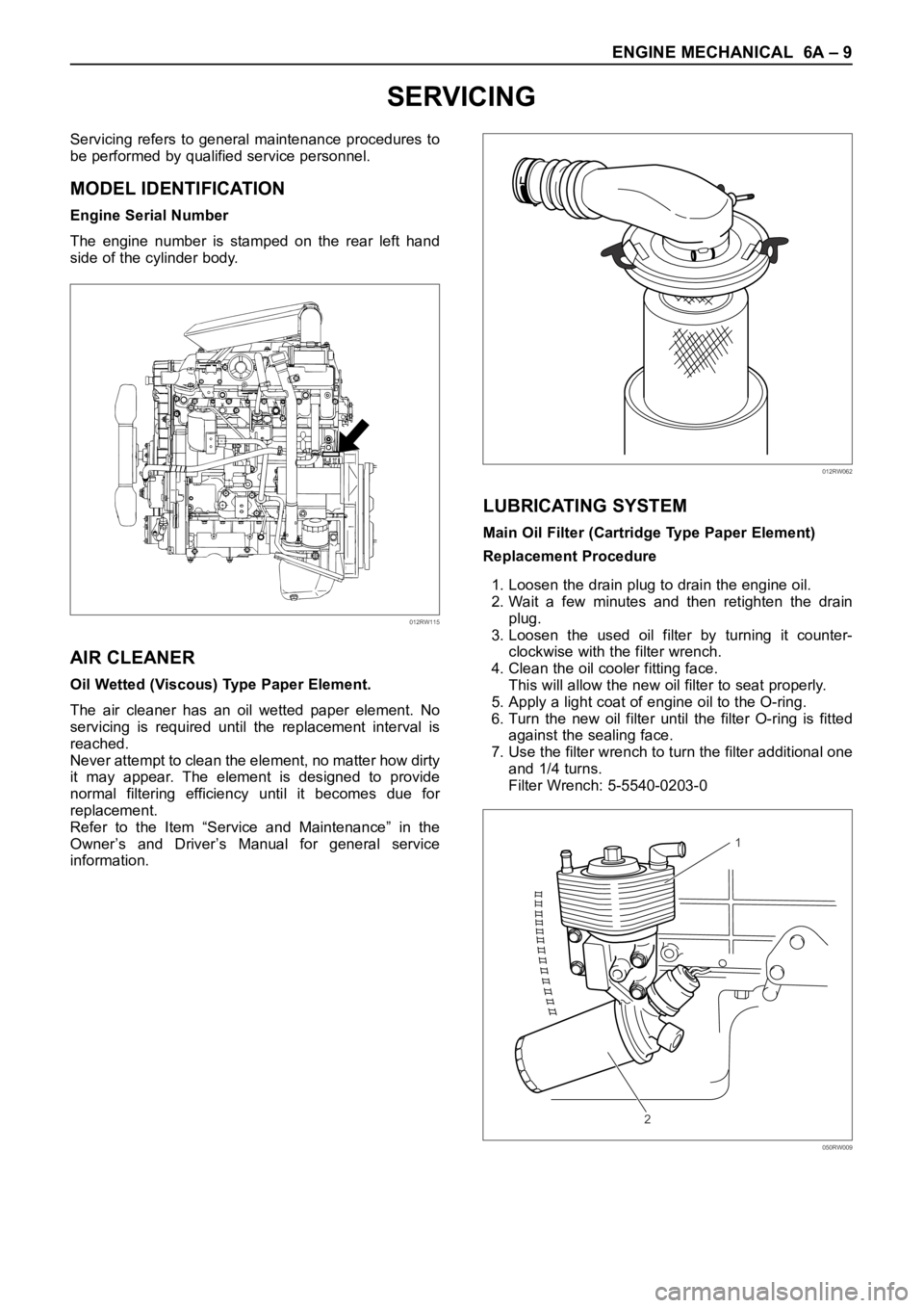
MODEL IDENTIFICATION
Engine Serial Number
The engine number is stamped on the rear left hand
side of the cylinder body.
AIR CLEANER
Oil Wetted (Viscous) Type Paper Element.
The air cleaner has an oil wetted paper element. No
servicing is required until the replacement interval is
reached.
Never attempt to clean the element, no matter how dirty
it may appear. The element is designed to provide
normal filtering efficiency until it becomes due for
replacement.
Refer to the Item “Service and Maintenance” in the
Owner’s and Driver’s Manual for general service
information.
LUBRICATING SYSTEM
Main Oil Filter (Cartridge Type Paper Element)
Replacement Procedure
1. Loosen the drain plug to drain the engine oil.
2. Wait a few minutes and then retighten the drain
plug.
3. Loosen the used oil filter by turning it counter-
clockwise with the filter wrench.
4. Clean the oil cooler fitting face.
This will allow the new oil filter to seat properly.
5. Apply a light coat of engine oil to the O-ring.
6. Turn the new oil filter until the filter O-ring is fitted
against the sealing face.
7. Use the filter wrench to turn the filter additional one
and 1/4 turns.
Filter Wrench: 5-5540-0203-0
012RW115
012RW062
1
2
050RW009