Page 4949 of 6000
6E–292
ENGINE DRIVEABILITY AND EMISSIONS
Crankshaft Position (CKP)
Sensor
Removal Procedure
1. Disconnect the negative battery cable.
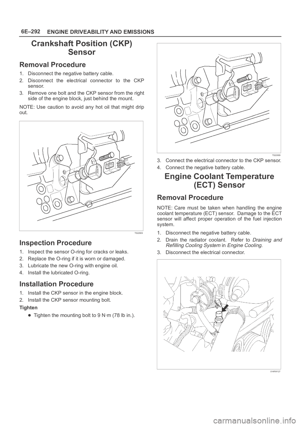
2. Disconnect the electrical connector to the CKP
sensor.
3. Remove one bolt and the CKP sensor from the right
side of the engine block, just behind the mount.
NOTE: Use caution to avoid any hot oil that might drip
out.
TS22909
Inspection Procedure
1. Inspect the sensor O-ring for cracks or leaks.
2. Replace the O-ring if it is worn or damaged.
3. Lubricate the new O-ring with engine oil.
4. Install the lubricated O-ring.
Installation Procedure
1. Install the CKP sensor in the engine block.
2. Install the CKP sensor mounting bolt.
Tighten
Tighten the mounting bolt to 9 Nꞏm (78 lb in.).
TS22909
3. Connect the electrical connector to the CKP sensor.
4. Connect the negative battery cable.
Engine Coolant Temperature
(ECT) Sensor
Removal Procedure
NOTE: Care must be taken when handling the engine
coolant temperature (ECT) sensor. Damage to the ECT
sensor will affect proper operation of the fuel injection
system.
1. Disconnect the negative battery cable.
2. Drain the radiator coolant. Refer to
Draining and
Refilling Cooling System
in Engine Cooling.
3. Disconnect the electrical connector.
014RW127
Page 4953 of 6000
6E–296
ENGINE DRIVEABILITY AND EMISSIONS
Knock Sensor (KS)
Removal Procedure
1. Disconnect the negative battery cable.
2. Drain the cooling system. Refer to
Draining and
Filling the Cooling System
in Engine Cooling.
3. Remove the engine cover.
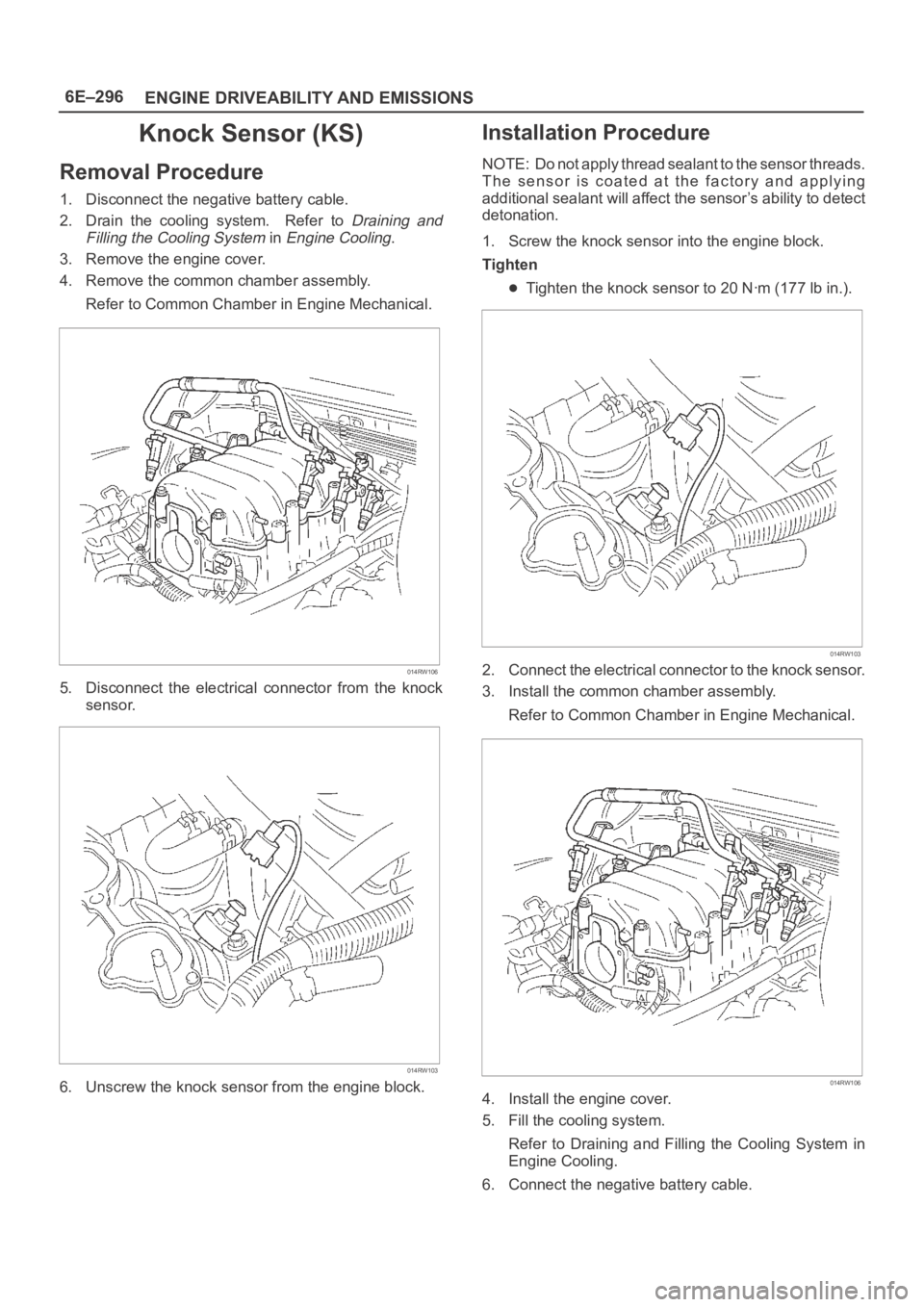
4. Remove the common chamber assembly.
Refer to Common Chamber in Engine Mechanical.
014RW106
5. Disconnect the electrical connector from the knock
sensor.
014RW103
6. Unscrew the knock sensor from the engine block.
Installation Procedure
NOTE: Do not apply thread sealant to the sensor threads.
The sensor is coated at the factory and applying
additional sealant will affect the sensor’s ability to detect
detonation.
1. Screw the knock sensor into the engine block.
Tighten
Tighten the knock sensor to 20 Nꞏm (177 lb in.).
014RW103
2. Connect the electrical connector to the knock sensor.
3. Install the common chamber assembly.
Refer to Common Chamber in Engine Mechanical.
014RW106
4. Install the engine cover.
5. Fill the cooling system.
Refer to Draining and Filling the Cooling System in
Engine Cooling.
6. Connect the negative battery cable.
Page 4956 of 6000
6E–299 ENGINE DRIVEABILITY AND EMISSIONS
damage, therefore, it is important to use care when
handling and testing electronic components.
NOTE: To prevent possible Electrostatic Discharge
damage, follow these guidelines:
Do not touch the control module connector pins or
soldered components on the control module circuit
board.
Do not open the replacement part package until the
part is ready to be installed.
Before removing the part from the package, ground
the package to a known good ground on the vehicle.
If the part has been handled while sliding across the
seat, or while sitting down from a standing position, or
while walking a distance, touch a known good ground
before installing the part.
NOTE: To prevent internal PCM damage, the ignition
must be in the “OFF” position in order to disconnect or
reconnect power to the PCM (for example: battery cable,
PCM pigtail, PCM fuse, jumper cables, etc.).
IMPORTANT:When replacing the production PCM
with a service PCM, it is important to transfer the
broadcast code and production PCM number to the
service PCM label. This will allow positive identification of
PCM parts throughout the service life of the vehicle. Do
not record this information on the metal PCM cover.
IMPORTANT:The ignition should always be in the
“OFF” position in order to install or remove the PCM
connectors.
Service of the PCM should normally consist of either re-
placement of the PCM or EEPROM programming. If the
diagnostic procedures call for the PCM to be replaced,
the PCM should be checked first to ensure it is the correct
part. If it is, remove the faulty PCM and install the new
service PCM.
The service PCM EEPROM will not be programmed.
DTC P0601 indicates the check sum error.
Removal Procedure
1. Disconnect the negative battery cable.
2. Block the wheels.
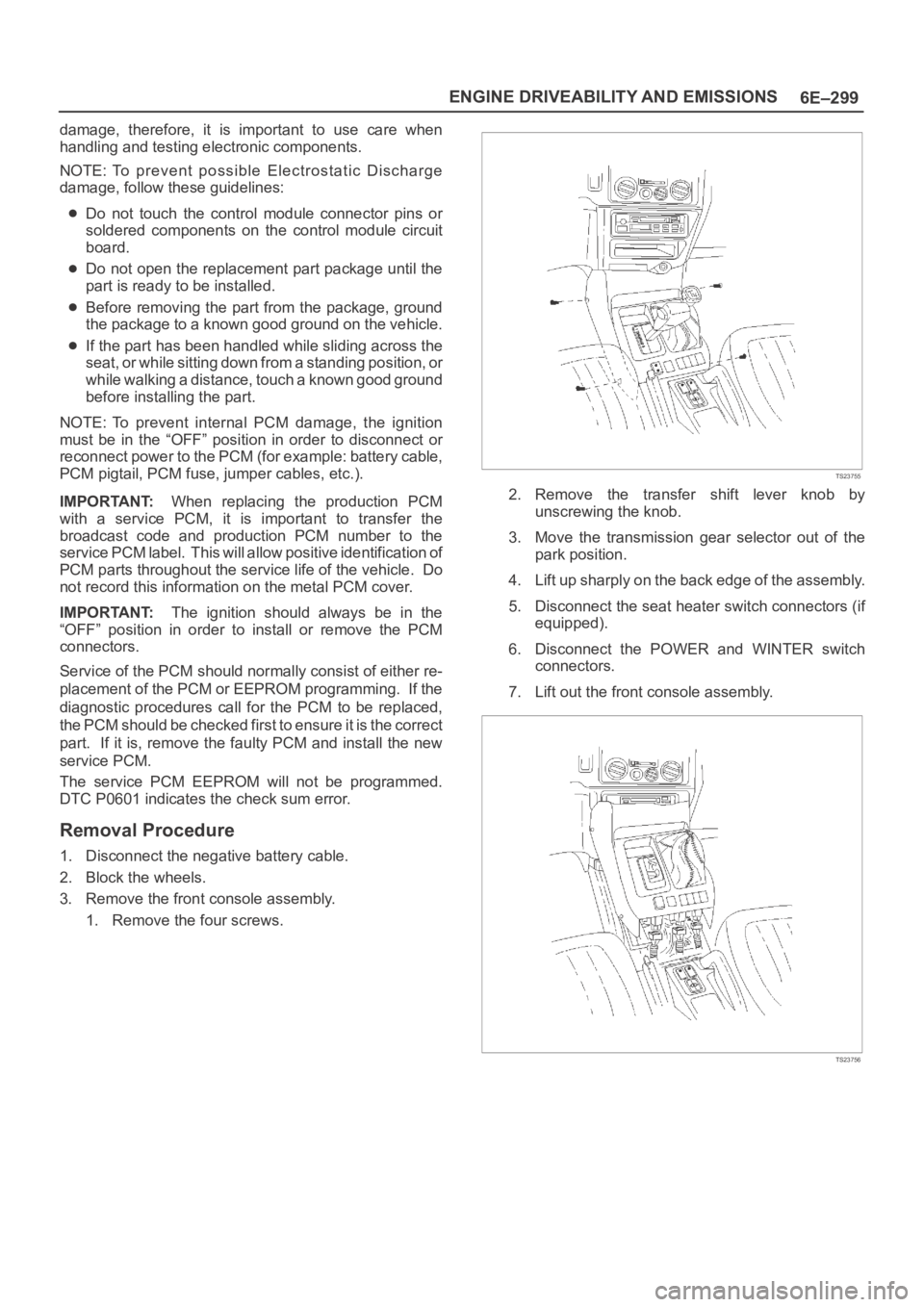
3. Remove the front console assembly.
1. Remove the four screws.
TS23755
2. Remove the transfer shift lever knob by
unscrewing the knob.
3. Move the transmission gear selector out of the
park position.
4. Lift up sharply on the back edge of the assembly.
5. Disconnect the seat heater switch connectors (if
equipped).
6. Disconnect the POWER and WINTER switch
connectors.
7. Lift out the front console assembly.
TS23756
Page 4964 of 6000
6E–307 ENGINE DRIVEABILITY AND EMISSIONS
4. Install the accelerator control cable (on the throttle
valve end).
101RW006
5. Install the adjusting nut.
101RW007
6. Adjust the accelerator cable at the throttle body.
Refer to
Accelerator Cable Adjustment.
7. Install the engine cover.
Adjustment Procedure
1. Loosen the adjusting nut and lock nut.
2. Pull outer cable closing fully the throttle valve.
3. Tighten adjusting nut and lock nut temporarily.
035RW004
4. Loosen adjusting nut by three turns and tighten lock
nut. Then, manually operating the throttle valve,
make sure that the valve lever returns up to the
stopper screw.
IMPORTANT:The valve lever must return up to the
stopper screw. If the valve lever does not reach the
stopper screw, repeat the procedure again from step 1.
5. It does not reach the stopper screw, repeat from step
1.
TS23782
Page 4967 of 6000
6E–310
ENGINE DRIVEABILITY AND EMISSIONS
Pedal Stroke Adjustment Procedure
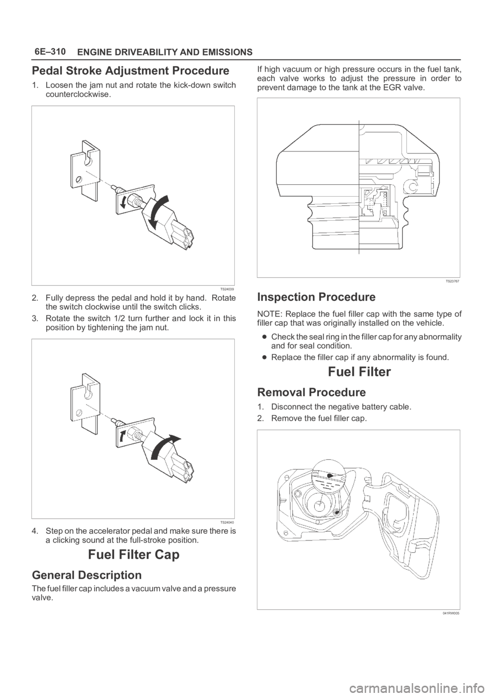
1. Loosen the jam nut and rotate the kick-down switch
counterclockwise.
TS24039
2. Fully depress the pedal and hold it by hand. Rotate
the switch clockwise until the switch clicks.
3. Rotate the switch 1/2 turn further and lock it in this
position by tightening the jam nut.
TS24040
4. Step on the accelerator pedal and make sure there is
a clicking sound at the full-stroke position.
Fuel Filter Cap
General Description
The fuel filler cap includes a vacuum valve and a pressure
valve.If high vacuum or high pressure occurs in the fuel tank,
each valve works to adjust the pressure in order to
prevent damage to the tank at the EGR valve.
TS23767
Inspection Procedure
NOTE: Replace the fuel filler cap with the same type of
filler cap that was originally installed on the vehicle.
Check the seal ring in the filler cap for any abnormality
and for seal condition.
Replace the filler cap if any abnormality is found.
Fuel Filter
Removal Procedure
1. Disconnect the negative battery cable.
2. Remove the fuel filler cap.
041RW005
Page 4989 of 6000
6E–332
ENGINE DRIVEABILITY AND EMISSIONS
2. Cover the splice with tape in order to insulate it from
the other wires.
053
3. Twist the wires as they were before starting this
procedure.
054
4. Tape the wires with electrical tape. Hold in place.
055
Weather-Pack Connector
Tools Required
J 28742-A Weather-Pack II Terminal Remover
Removal Procedure
A Weather-Pack connector can be identified by a rubber
seal at the rear of the connector. This engine room
connector protects against moisture and dirt, which could
from oxidation and deposits on the terminals. This
protection is important, because of the low voltage and
the low amperage found in the electronic systems.
1. Open the secondary lock hinge on the connector.
070
Page 4990 of 6000
6E–333 ENGINE DRIVEABILITY AND EMISSIONS
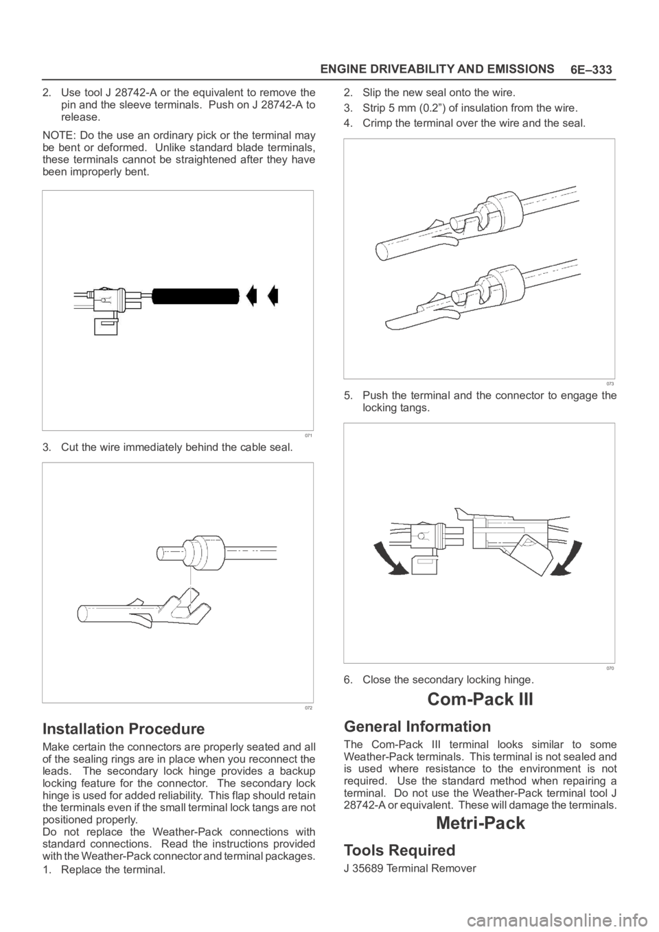
2. Use tool J 28742-A or the equivalent to remove the
pin and the sleeve terminals. Push on J 28742-A to
release.
NOTE: Do the use an ordinary pick or the terminal may
be bent or deformed. Unlike standard blade terminals,
these terminals cannot be straightened after they have
been improperly bent.
071
3. Cut the wire immediately behind the cable seal.
072
Installation Procedure
Make certain the connectors are properly seated and all
of the sealing rings are in place when you reconnect the
leads. The secondary lock hinge provides a backup
locking feature for the connector. The secondary lock
hinge is used for added reliability. This flap should retain
the terminals even if the small terminal lock tangs are not
positioned properly.
Do not replace the Weather-Pack connections with
standard connections. Read the instructions provided
with the Weather-Pack connector and terminal packages.
1. Replace the terminal.2. Slip the new seal onto the wire.
3. Strip 5 mm (0.2”) of insulation from the wire.
4. Crimp the terminal over the wire and the seal.
073
5. Push the terminal and the connector to engage the
locking tangs.
070
6. Close the secondary locking hinge.
Com-Pack III
General Information
The Com-Pack III terminal looks similar to some
Weather-Pack terminals. This terminal is not sealed and
is used where resistance to the environment is not
required. Use the standard method when repairing a
terminal. Do not use the Weather-Pack terminal tool J
28742-A or equivalent. These will damage the terminals.
Metri-Pack
Tools Required
J 35689 Terminal Remover
Page 4991 of 6000
6E–334
ENGINE DRIVEABILITY AND EMISSIONS
Removal Procedure
S o m e c o n n e c t o r s u s e t e r m i n a l s c a l l e d M e t r i - P a c k S e r i e s
150. These may be used at the engine coolant
temperature (ECT) sensor.
1. Slide the seal (1) back on the wire.
2. Insert the J 35689 tool or equivalent (3) in order to
release the terminal locking tang (2).
060
3. Push the wire and the terminal out through the
connector. If you reuse the terminal, reshape the
locking tang.
Installation Procedure
Metri-Pack terminals are also referred to as “pull-to-seat”
terminals.
1. In order to install a terminal on a wire, the wire must be
inserted through the seal (2) and through the
connector (3).
2. The terminal (1) is then crimped onto the wire.
061
3. Then the terminal is pulled back into the connector to
seat it in place.