Page 3424 of 6000

9A–4 SEAT BELT SYSTEM
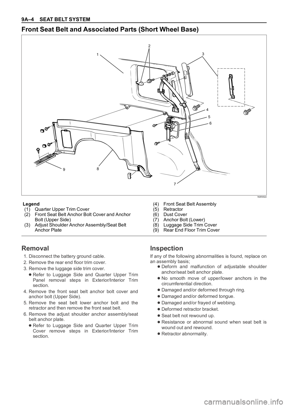
760RW024
Legend
(1) Quarter Upper Trim Cover
(2) Front Seat Belt Anchor Bolt Cover and Anchor
Bolt (Upper Side)
(3) Adjust Shoulder Anchor Assembly/Seat Belt
Anchor Plate(4) Front Seat Belt Assembly
(5) Retractor
(6) Dust Cover
(7) Anchor Bolt (Lower)
(8) Luggage Side Trim Cover
(9) Rear End Floor Trim Cover
Front Seat Belt and Associated Parts (Short Wheel Base)
3
4
5
6
7
8
912
Removal
1. Disconnect the battery ground cable.
2. Remove the rear end floor trim cover.
3. Remove the luggage side trim cover.
Refer to Luggage Side and Quarter Upper Trim
Panel removal steps in Exterior/Interior Trim
section.
4. Remove the front seat belt anchor bolt cover and
anchor bolt (Upper Side).
5. Remove the seat belt lower anchor bolt and the
retractor and then remove the front seat belt.
6. Remove the adjust shoulder anchor assembly/seat
belt anchor plate.
Refer to Luggage Side and Quarter Upper Trim
Cover remove steps in Exterior/Interior Trim
section.
Inspection
If any of the following abnormalities is found, replace on
an assembly basis;
Deform and malfunction of adjustable shoulder
anchor/seat belt anchor plate.
No smooth move of upper/lower anchors in the
circumferential direction.
Damaged and/or deformed through ring.
Damaged and/or deformed tongue.
Damaged and/or frayed of webbing.
Deformed retractor bracket.
Seat belt not rewound up.
Resistance or abnormal sound when seat belt is
wound out and rewound.
Retractor abnormality.
Page 3425 of 6000

SEAT BELT SYSTEM 9A–5
Inspection of retractor
1. ELR (Emergency Locking Retractor) lock inclining
angle check.
When the retractor is moved gently from its installing
position, make sure it is not locked within 15° in any
directions, and it remains locked at 45° or larger.
2. ELR lock check.
When the seat belt is drawn slowly with the retractor
installed, make sure it is not locked. And when it is
drawn quickly, make sure it is locked.
3. ALR (Automatic Locking Retractor)/ELR check
(Except for driver’s seat).
When rewound after winding out the seat belt, make
sure the seat belt cannot be taken out. After
rewinding, make sure it has returned to its normal
operation.
CAUTION: Do not disassemble the retractor.
Installation
To install, follow the removal steps in the reverse order,
noting the following points;
1. Pass the seat belt through the lower trim cover hole,
and tighten the seat belt anchor bolts to the specified
torque.
Torque: 39 Nꞏm (4.0 kgꞏm/29 lb ft)
2. After installing the trim cover to the body panel
securely, close the lower trim cover.
Page 3426 of 6000

9A–6 SEAT BELT SYSTEM
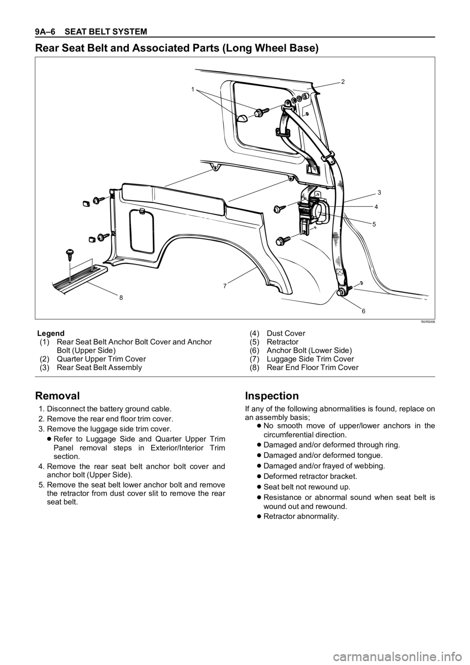
760RS006
Legend
(1) Rear Seat Belt Anchor Bolt Cover and Anchor
Bolt (Upper Side)
(2) Quarter Upper Trim Cover
(3) Rear Seat Belt Assembly(4) Dust Cover
(5) Retractor
(6) Anchor Bolt (Lower Side)
(7) Luggage Side Trim Cover
(8) Rear End Floor Trim Cover
Rear Seat Belt and Associated Parts (Long Wheel Base)
12
3
4
5
6 7
8
Removal
1. Disconnect the battery ground cable.
2. Remove the rear end floor trim cover.
3. Remove the luggage side trim cover.
Refer to Luggage Side and Quarter Upper Trim
Panel removal steps in Exterior/Interior Trim
section.
4. Remove the rear seat belt anchor bolt cover and
anchor bolt (Upper Side).
5. Remove the seat belt lower anchor bolt and remove
the retractor from dust cover slit to remove the rear
seat belt.
Inspection
If any of the following abnormalities is found, replace on
an assembly basis;
No smooth move of upper/lower anchors in the
circumferential direction.
Damaged and/or deformed through ring.
Damaged and/or deformed tongue.
Damaged and/or frayed of webbing.
Deformed retractor bracket.
Seat belt not rewound up.
Resistance or abnormal sound when seat belt is
wound out and rewound.
Retractor abnormality.
Page 3427 of 6000
SEAT BELT SYSTEM 9A–7
Inspection of retractor
1. ELR (Emergency Locking Retractor) lock inclining
angle check.
When the retractor is moved gently from its installing
position, make sure it is not locked within 15° in any
directions, and it remains locked at 45° or larger.
2. ELR lock check.
When the seat belt is drawn slowly with the retractor
installed, make sure it is not locked. And when it is
drawn quickly, make sure it is locked.
3. ALR (Automatic Locking Retractor)/ELR check
(Except for driver’s seat).
When rewound after winding out the seat belt, make
sure the seat belt cannot be taken out. After
rewinding, make sure it has returned to its normal
operation.
CAUTION: Do not disassemble the retractor.
Installation
To install, follow the removal steps in the reverse order,
noting the following point.
1. Tighten the seat belt anchor bolts to the specified
torque.
Torque: 39 Nꞏm (4.0 kgꞏm/29 lb ft)
Page 3429 of 6000

SEAT BELT SYSTEM 9A–9
3. Remove the rear end floor trim cover.
4. Remove the luggage side trim cover.
Refer to Luggage Side and Quarter Upper Trim
Panel removal steps in Exterior/Interior Trim
section.
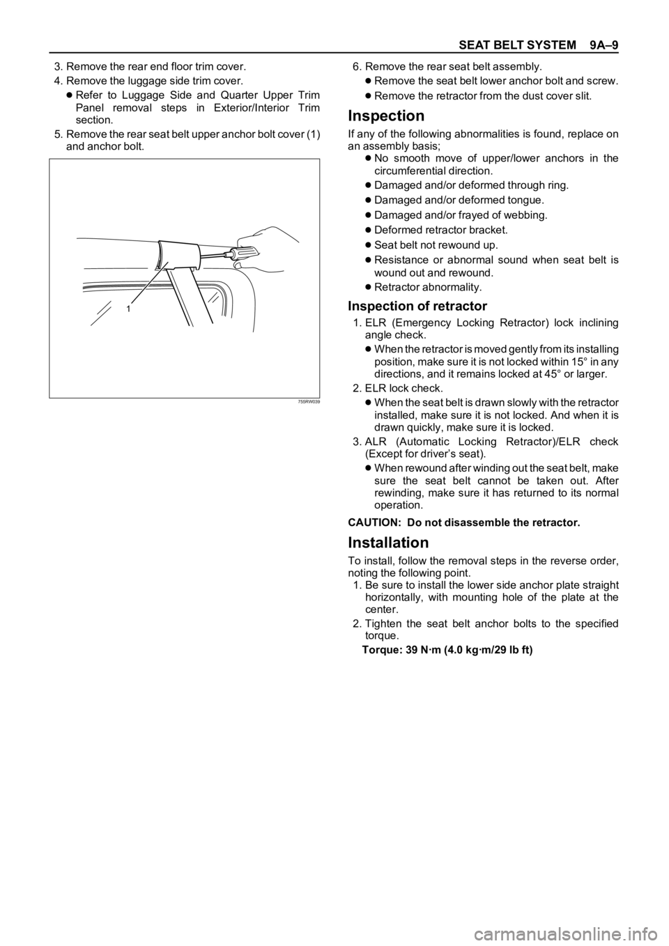
5. Remove the rear seat belt upper anchor bolt cover (1)
and anchor bolt.6. Remove the rear seat belt assembly.
Remove the seat belt lower anchor bolt and screw.
Remove the retractor from the dust cover slit.
Inspection
If any of the following abnormalities is found, replace on
an assembly basis;
No smooth move of upper/lower anchors in the
circumferential direction.
Damaged and/or deformed through ring.
Damaged and/or deformed tongue.
Damaged and/or frayed of webbing.
Deformed retractor bracket.
Seat belt not rewound up.
Resistance or abnormal sound when seat belt is
wound out and rewound.
Retractor abnormality.
Inspection of retractor
1. ELR (Emergency Locking Retractor) lock inclining
angle check.
When the retractor is moved gently from its installing
position, make sure it is not locked within 15° in any
directions, and it remains locked at 45° or larger.
2. ELR lock check.
When the seat belt is drawn slowly with the retractor
installed, make sure it is not locked. And when it is
drawn quickly, make sure it is locked.
3. ALR (Automatic Locking Retractor)/ELR check
(Except for driver’s seat).
When rewound after winding out the seat belt, make
sure the seat belt cannot be taken out. After
rewinding, make sure it has returned to its normal
operation.
CAUTION: Do not disassemble the retractor.
Installation
To install, follow the removal steps in the reverse order,
noting the following point.
1. Be sure to install the lower side anchor plate straight
horizontally, with mounting hole of the plate at the
center.
2. Tighten the seat belt anchor bolts to the specified
torque.
Torque: 39 Nꞏm (4.0 kgꞏm/29 lb ft)
1
755RW039
Page 3431 of 6000

SEAT BELT SYSTEM 9A–11
Inspection
If any of the following abnormalities is found, replace on
an assembly basis;
No smooth move of upper/lower anchors in the
circumferential direction.
Damaged and/or deformed through ring.
Damaged and/or deformed tongue.
Damaged and/or frayed of webbing.
Deformed retractor bracket.
Seat belt not rewound up.
Resistance or abnormal sound when seat belt is
wound out and rewound.
Retractor abnormality.
Inspection of retractor
1. ELR (Emergency Locking Retractor) lock inclining
angle check.
When the retractor is moved gently from its installing
position, make sure it is not locked within 15° in any
directions, and it remains locked at 45° or larger.
2. ELR lock check.
When the seat belt is drawn slowly with the retractor
installed, make sure it is not locked. And when it is
drawn quickly, make sure it is locked.
CAUTION: Do not disassemble the retractor.
Installation
To install, follow the removal steps in the reverse order,
noting the following point.
1. Be sure to install the lower side anchor plate (1)
straight against the longitudinal direction of the
vehicle with mounting hole of the plate at the center.
2. Tighten the seat belt anchor bolts to the specified
torque.
Torque: 39 Nꞏm (4.0 kgꞏm/29 lb ft)
Page 3436 of 6000
9A–16 SEAT BELT SYSTEM
Rear Seat Strikers
Removal
1. Fold the rear seat assembly to the front direction.
2. Remove the luggage floor box(1) (LꞏWꞏB).
Remove the striker cover(3) (SꞏWꞏB).
3. Remove the rear seat striker(2).
Installation
To install, follow the removal steps in the reverse order,
noting the following point.
1. Tighten the striker fixing bolts to the specified torque.
Torque: 40 Nꞏm (4.1 kgꞏm/30 lb ft)
L.W.B
1
2
S.W.B
3
2
755RW045
Removal
1. Disconnect the battery ground cable.
2. Remove the striker cover (1).
3. Remove the third seat striker (2).
Installation
To install, follow the removal steps in the reverse order,
noting the following point.
1. Tighten the striker fixing nuts to the specified torque.
Torque: 39 Nꞏm (4.0 kgꞏm/29 lb ft)
Third Seat Striker
1
2
755RW041
Page 3475 of 6000

SUPPLEMENTAL RESTRAINT SYSTEM 9J–38
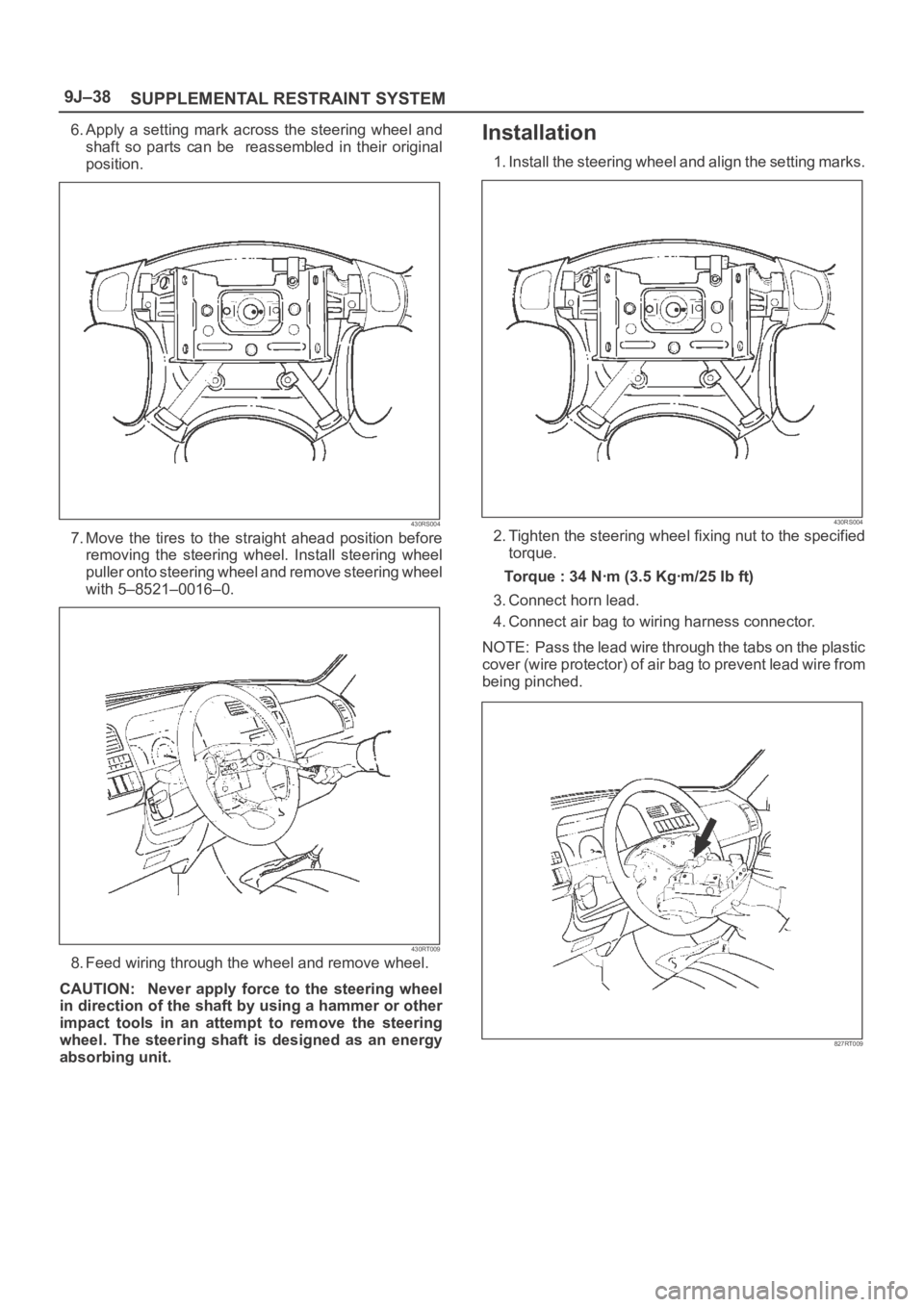
6. Apply a setting mark across the steering wheel and
shaft so parts can be reassembled in their original
position.
430RS004
7. Move the tires to the straight ahead position before
removing the steering wheel. Install steering wheel
puller onto steering wheel and remove steering wheel
with 5–8521–0016–0.
430RT009
8. Feed wiring through the wheel and remove wheel.
CAUTION: Never apply force to the steering wheel
in direction of the shaft by using a hammer or other
impact tools in an attempt to remove the steering
wheel. The steering shaft is designed as an energy
absorbing unit.
Installation
1. Install the steering wheel and align the setting marks.
430RS004
2. Tighten the steering wheel fixing nut to the specified
torque.
Torque : 34 Nꞏm (3.5 Kgꞏm/25 Ib ft)
3. Connect horn lead.
4. Connect air bag to wiring harness connector.
NOTE: Pass the lead wire through the tabs on the plastic
cover (wire protector) of air bag to prevent lead wire from
being pinched.
827RT009