Page 3995 of 6000
4A2A–26
DIFFERENTIAL (REAR 220mm)
Clearance between the side gear and the
differential box:
Standard: 0.05–0.12 mm (0.002–0.005 in)
Limit: 0.15 mm(0.006 in)
425RS046
Legend
(1) Side Gear
(2) Differential Box
Play in splines between the side gear and
the axle shaft:
Standard: 0.07–0.38 mm(0.003 –0.014 in)
Limit:0.5m (0.02 in)
425RS047
Reassembly
1. Install thrust washer.
2. Install side gear.
3. Install the pinion gear by engaging it with the side
gears while turning both pinion gears simultaneously
in the same direction.
425RS048
4. Install cross pin.
1. Be sure to install the cross pin so that it is in
alignment with the lock pin hole in the differential
cage.
425RS049
2. Adjust the backlash between the side gear and
the pinion gear.
Backlash:0.13 – 0.18 mm (0.005– 0.007 in)
Page 4001 of 6000
4A2A–32
DIFFERENTIAL (REAR 220mm)
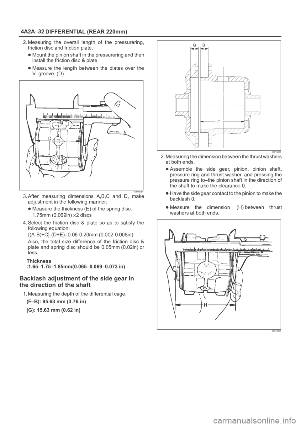
2. Measuring the overall length of the pressurering,
friction disc and friction plate.
Mount the pinion shaft in the pressurering and then
install the friction disc & plate.
Measure the length between the plates over the
V–groove. (D)
425RS065
3. After measuring dimensions A,B,C and D, make
adjustment in the following manner:
Measure the thickness (E) of the spring disc.
1.75mm (0.069in)
2discs
4. Select the friction disc & plate so as to satisfy the
following equation:
{(A-B)+C}-(D+E)=0.06-0.20mm (0.002-0.008in)
Also, the total size difference of the friction disc &
plate and spring disc should be 0.05mm (0.02in) or
less.
Thickness
:1.65–1.75–1.85mm(0.065–0.069–0.073 in)
Backlash adjustment of the side gear in
the direction of the shaft
1. Measuring the depth of the differential cage.
(F–B): 95.63 mm (3.76 in)
(G): 15.63 mm (0.62 in)
425RS066
2. Measuring the dimension between the thrust washers
at both ends.
Assemble the side gear, pinion, pinion shaft,
pressure ring and thrust washer, and pressing the
pressure ring to–the pinion shaft in the direction of
the shaft to make the clearance 0.
Have the side gear contact to the pinion to make the
backlash 0.
Measure the dimension (H) between thrust
washers at both ends.
425RS067
Page 4002 of 6000
DIFFERENTIAL (REAR 220mm)
4A2A–33
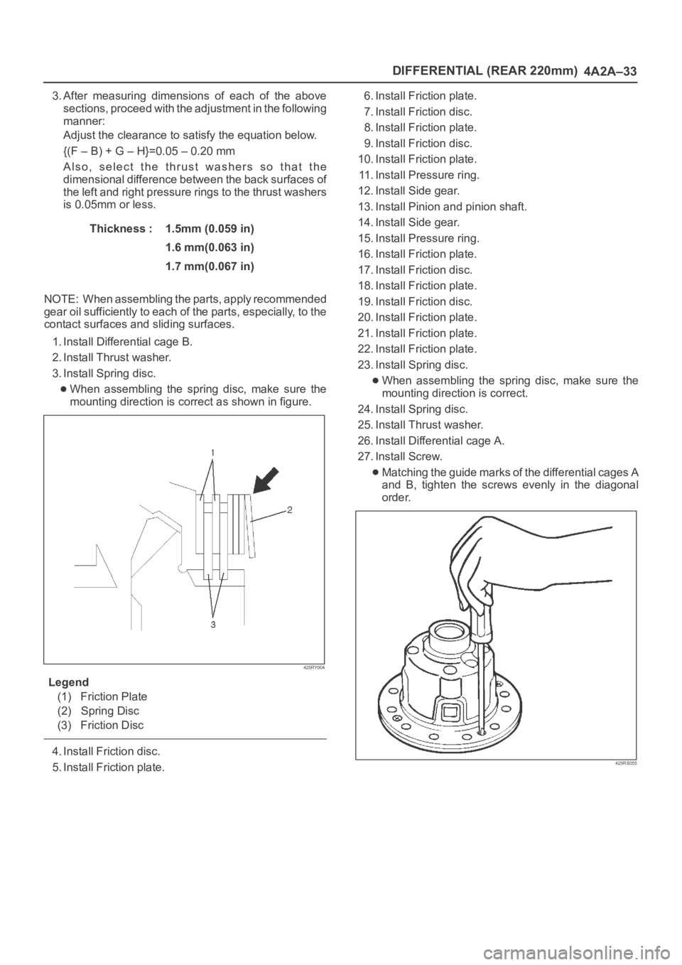
3. After measuring dimensions of each of the above
sections, proceed with the adjustment in the following
manner:
Adjust the clearance to satisfy the equation below.
{(F – B) + G – H}=0.05 – 0.20 mm
Also, select the thrust washers so that the
dimensional difference between the back surfaces of
the left and right pressure rings to the thrust washers
is 0.05mm or less.
Thickness : 1.5mm (0.059 in)
1.6 mm(0.063 in)
1.7 mm(0.067 in)
NOTE: When assembling the parts, apply recommended
gear oil sufficiently to each of the parts, especially, to the
contact surfaces and sliding surfaces.
1. Install Differential cage B.
2. Install Thrust washer.
3. Install Spring disc.
When assembling the spring disc, make sure the
mounting direction is correct as shown in figure.
425RY004
Legend
(1) Friction Plate
(2) Spring Disc
(3) Friction Disc
4. Install Friction disc.
5. Install Friction plate.6. Install Friction plate.
7. Install Friction disc.
8. Install Friction plate.
9. Install Friction disc.
10. Install Friction plate.
11. Install Pressure ring.
12. Install Side gear.
13. Install Pinion and pinion shaft.
14. Install Side gear.
15. Install Pressure ring.
16. Install Friction plate.
17. Install Friction disc.
18. Install Friction plate.
19. Install Friction disc.
20. Install Friction plate.
21. Install Friction plate.
22. Install Friction plate.
23. Install Spring disc.
When assembling the spring disc, make sure the
mounting direction is correct.
24. Install Spring disc.
25. Install Thrust washer.
26. Install Differential cage A.
27. Install Screw.
Matching the guide marks of the differential cages A
and B, tighten the screws evenly in the diagonal
order.
425RS055
Page 4033 of 6000
4A2B–26DIFFERENTIAL (REAR 244mm)
Clearance between the side gear and the differential
box.
Standard: 0.032 – 0.105 mm (0.001 – 0.004 in)
Limit: 0.105 mm (0.004 in)
425RY00005
Legend
(1) Side gear
(2) Differential box
Play in splines between the side gear and the axle
shaft.
Standard: 0.07 – 0.38 mm (0.003 – 0.014 in)
Limit: 0.5 mm (0.02 in)
425RY00006
Reassembly
Differential cage
Thrust washer
Side gear
Pinion gear
1. Install the pinion gear by engaging it with the side
gears while turning both pinion gears simultaneously
in the same direction.
2. Install the pinion mate gear with thrust washer by
engaging it with the side gears while turning both
pinion mate gears simultaneously in the same
direction.
425RS048
3. Install differential shaft.
1. Be sure to install the differential shaft so that it is in
alignment with the lock pin hole in the differential
cage.
425RS049
Page 4039 of 6000
4A2B–32DIFFERENTIAL (REAR 244mm)
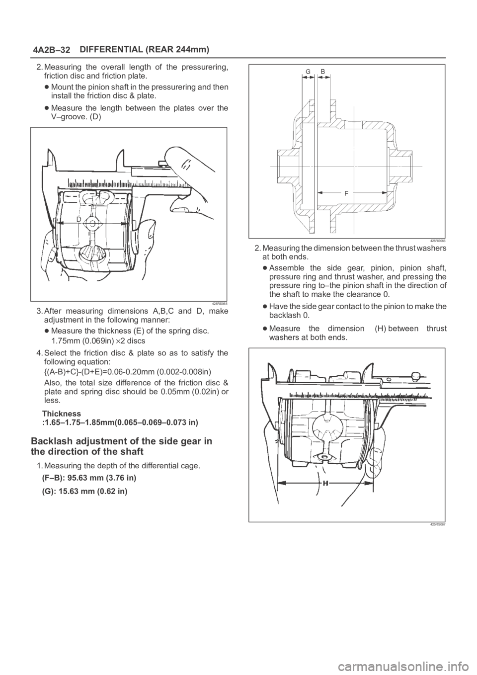
2. Measuring the overall length of the pressurering,
friction disc and friction plate.
Mount the pinion shaft in the pressurering and then
install the friction disc & plate.
Measure the length between the plates over the
V–groove. (D)
425RS065
3. After measuring dimensions A,B,C and D, make
adjustment in the following manner:
Measure the thickness (E) of the spring disc.
1.75mm (0.069in)
2discs
4. Select the friction disc & plate so as to satisfy the
following equation:
{(A-B)+C}-(D+E)=0.06-0.20mm (0.002-0.008in)
Also, the total size difference of the friction disc &
plate and spring disc should be 0.05mm (0.02in) or
less.
Thickness
:1.65–1.75–1.85mm(0.065–0.069–0.073 in)
Backlash adjustment of the side gear in
the direction of the shaft
1. Measuring the depth of the differential cage.
(F–B): 95.63 mm (3.76 in)
(G): 15.63 mm (0.62 in)
425RS066
2. Measuring the dimension between the thrust washers
at both ends.
Assemble the side gear, pinion, pinion shaft,
pressure ring and thrust washer, and pressing the
pressure ring to–the pinion shaft in the direction of
the shaft to make the clearance 0.
Have the side gear contact to the pinion to make the
backlash 0.
Measure the dimension (H) between thrust
washers at both ends.
425RS067
Page 4040 of 6000
DIFFERENTIAL (REAR 244mm)
4A2B–33
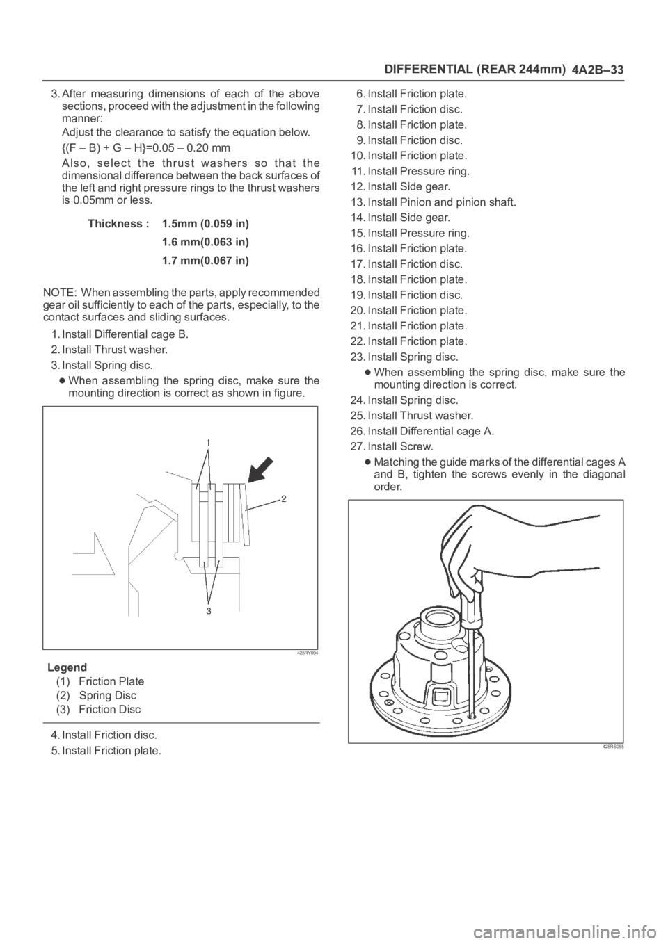
3. After measuring dimensions of each of the above
sections, proceed with the adjustment in the following
manner:
Adjust the clearance to satisfy the equation below.
{(F – B) + G – H}=0.05 – 0.20 mm
Also, select the thrust washers so that the
dimensional difference between the back surfaces of
the left and right pressure rings to the thrust washers
is 0.05mm or less.
Thickness : 1.5mm (0.059 in)
1.6 mm(0.063 in)
1.7 mm(0.067 in)
NOTE: When assembling the parts, apply recommended
gear oil sufficiently to each of the parts, especially, to the
contact surfaces and sliding surfaces.
1. Install Differential cage B.
2. Install Thrust washer.
3. Install Spring disc.
When assembling the spring disc, make sure the
mounting direction is correct as shown in figure.
425RY004
Legend
(1) Friction Plate
(2) Spring Disc
(3) Friction Disc
4. Install Friction disc.
5. Install Friction plate.6. Install Friction plate.
7. Install Friction disc.
8. Install Friction plate.
9. Install Friction disc.
10. Install Friction plate.
11. Install Pressure ring.
12. Install Side gear.
13. Install Pinion and pinion shaft.
14. Install Side gear.
15. Install Pressure ring.
16. Install Friction plate.
17. Install Friction disc.
18. Install Friction plate.
19. Install Friction disc.
20. Install Friction plate.
21. Install Friction plate.
22. Install Friction plate.
23. Install Spring disc.
When assembling the spring disc, make sure the
mounting direction is correct.
24. Install Spring disc.
25. Install Thrust washer.
26. Install Differential cage A.
27. Install Screw.
Matching the guide marks of the differential cages A
and B, tighten the screws evenly in the diagonal
order.
425RS055
Page 4222 of 6000
4C–16
DRIVE SHAFT SYSTEM
Inspection and Repair
Make necessary correction or parts replacement if wear,
damage, corrosion or any other abnormal condition are
found through inspection.
Check the following parts.
Hub
Hub bearing, oil seal
Knuckle spindle
Disc
Caliper
Free wheeling hub parts (Clutch, knob, follower,
inner, ring and spring)
ABS sensor ring (if so equipped)
For inspection and servicing of disc caliper, and relative
parts, refer to Brakes section.
Reassembly
1. Install spacer.
Apply about 1 g wheel bearing grease to both face of
spacer.
2. Install ring.
Apply about 3 g wheel bearing grease to inside face
of ring.
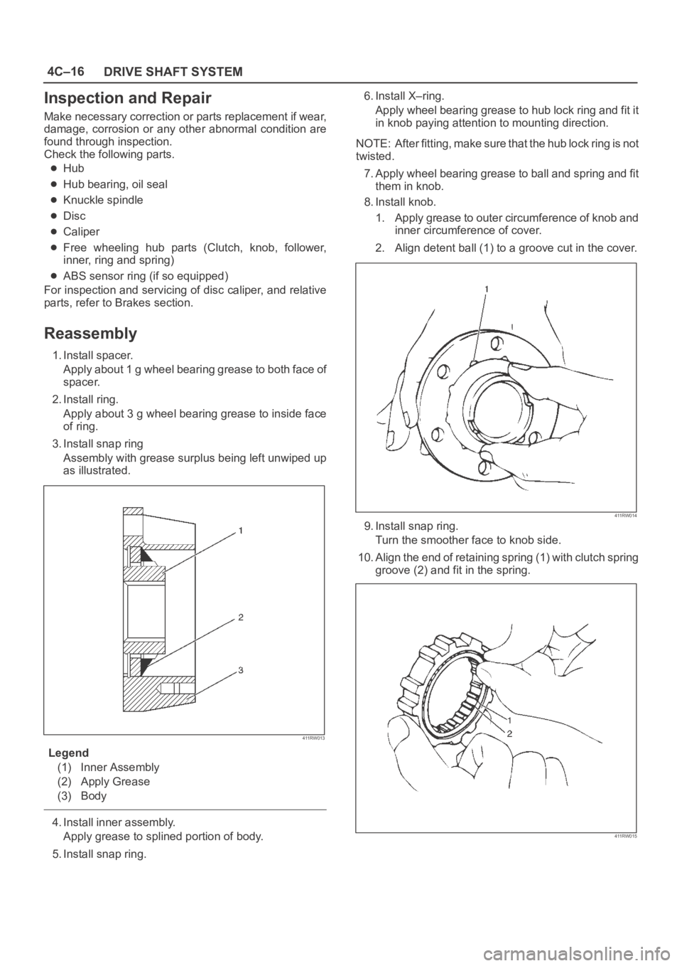
3. Install snap ring
Assembly with grease surplus being left unwiped up
as illustrated.
411RW013
Legend
(1) Inner Assembly
(2) Apply Grease
(3) Body
4. Install inner assembly.
Apply grease to splined portion of body.
5. Install snap ring.6. Install X–ring.
Apply wheel bearing grease to hub lock ring and fit it
in knob paying attention to mounting direction.
NOTE: After fitting, make sure that the hub lock ring is not
twisted.
7. Apply wheel bearing grease to ball and spring and fit
them in knob.
8. Install knob.
1. Apply grease to outer circumference of knob and
inner circumference of cover.
2. Align detent ball (1) to a groove cut in the cover.
411RW014
9. Install snap ring.
Turn the smoother face to knob side.
10. Align the end of retaining spring (1) with clutch spring
groove (2) and fit in the spring.
411RW015
Page 4232 of 6000
4C–26
DRIVE SHAFT SYSTEM
Reassembly
1. Install DOJ case to bracket.
2. Install oil seal and fix snap ring.
3. Install bearing and fix snap ring.
4. Install bracket to axle case. Tighten the bracket bolt to
the specified torque.
Torque: 116 Nꞏm (11.8 kgꞏm/85 lb ft)
5. Apply 150g of the specified grease in BJ .
6. Install dust seal .
7. Apply a thin coat of grease to the shaft for smooth
installation then install bellows.
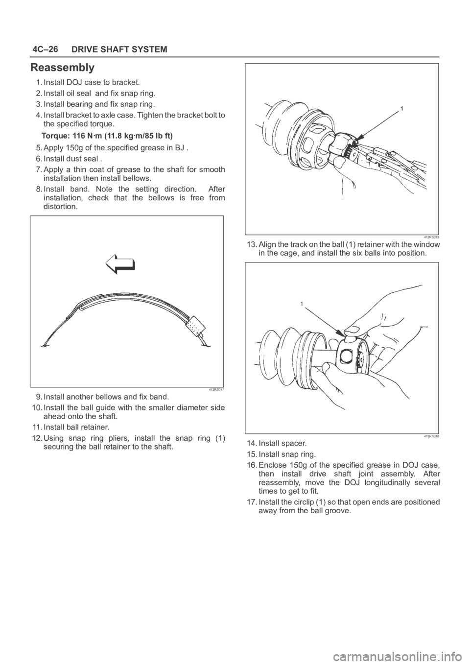
8. Install band. Note the setting direction. After
installation, check that the bellows is free from
distortion.
412RS017
9. Install another bellows and fix band.
10. Install the ball guide with the smaller diameter side
ahead onto the shaft.
11. Install ball retainer.
12. Using snap ring pliers, install the snap ring (1)
securing the ball retainer to the shaft.
412RS013
13. Align the track on the ball (1) retainer with the window
in the cage, and install the six balls into position.
412RS018
14. Install spacer.
15. Install snap ring.
16. Enclose 150g of the specified grease in DOJ case,
then install drive shaft joint assembly. After
reassembly, move the DOJ longitudinally several
times to get to fit.
17. Install the circlip (1) so that open ends are positioned
away from the ball groove.