1998 NISSAN PICK-UP Ignition
[x] Cancel search: IgnitionPage 1504 of 1659
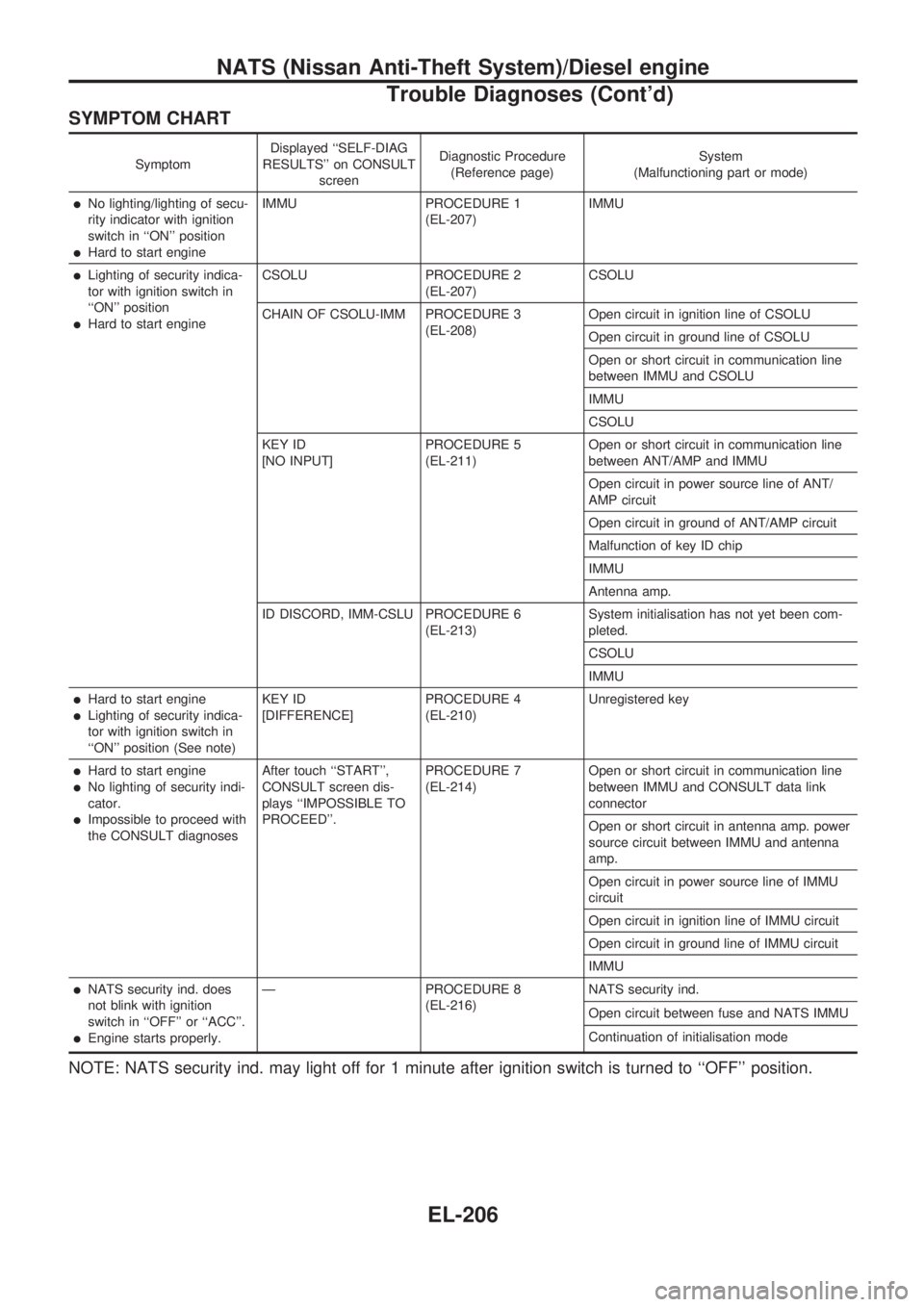
SYMPTOM CHART
SymptomDisplayed ``SELF-DIAG
RESULTS'' on CONSULT
screenDiagnostic Procedure
(Reference page)System
(Malfunctioning part or mode)
lNo lighting/lighting of secu-
rity indicator with ignition
switch in ``ON'' position
lHard to start engineIMMU PROCEDURE 1
(EL-207)IMMU
lLighting of security indica-
tor with ignition switch in
``ON'' position
lHard to start engineCSOLU PROCEDURE 2
(EL-207)CSOLU
CHAIN OF CSOLU-IMM PROCEDURE 3
(EL-208)Open circuit in ignition line of CSOLU
Open circuit in ground line of CSOLU
Open or short circuit in communication line
between IMMU and CSOLU
IMMU
CSOLU
KEY ID
[NO INPUT]PROCEDURE 5
(EL-211)Open or short circuit in communication line
between ANT/AMP and IMMU
Open circuit in power source line of ANT/
AMP circuit
Open circuit in ground of ANT/AMP circuit
Malfunction of key ID chip
IMMU
Antenna amp.
ID DISCORD, IMM-CSLU PROCEDURE 6
(EL-213)System initialisation has not yet been com-
pleted.
CSOLU
IMMU
lHard to start engine
lLighting of security indica-
tor with ignition switch in
``ON'' position (See note)KEY ID
[DIFFERENCE]PROCEDURE 4
(EL-210)Unregistered key
lHard to start engine
lNo lighting of security indi-
cator.
lImpossible to proceed with
the CONSULT diagnosesAfter touch ``START'',
CONSULT screen dis-
plays ``IMPOSSIBLE TO
PROCEED''.PROCEDURE 7
(EL-214)Open or short circuit in communication line
between IMMU and CONSULT data link
connector
Open or short circuit in antenna amp. power
source circuit between IMMU and antenna
amp.
Open circuit in power source line of IMMU
circuit
Open circuit in ignition line of IMMU circuit
Open circuit in ground line of IMMU circuit
IMMU
lNATS security ind. does
not blink with ignition
switch in ``OFF'' or ``ACC''.
lEngine starts properly.Ð PROCEDURE 8
(EL-216)NATS security ind.
Open circuit between fuse and NATS IMMU
Continuation of initialisation mode
NOTE: NATS security ind. may light off for 1 minute after ignition switch is turned to ``OFF'' position.
NATS (Nissan Anti-Theft System)/Diesel engine
Trouble Diagnoses (Cont'd)
EL-206
Page 1507 of 1659
VA
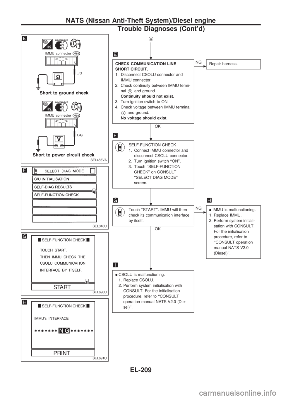
CHECK COMMUNICATION LINE
SHORT CIRCUIT.
1. Disconnect CSOLU connector and
IMMU connector.
2. Check continuity between IMMU termi-
nal
V5and ground.
Continuity should not exist.
3. Turn ignition switch to ON.
4. Check voltage between IMMU terminal
V5and ground.
No voltage should exist.
OK
cNG
Repair harness.
SELF-FUNCTION CHECK
1. Connect IMMU connector and
disconnect CSOLU connector.
2. Turn ignition switch ``ON''.
3. Touch ``SELF-FUNCTION
CHECK'' on CONSULT
``SELECT DIAG MODE''
screen.
Touch ``START''. IMMU will then
check its communication interface
by itself.
OK
cNGlIMMU is malfunctioning.
1. Replace IMMU.
2. Perform system initiali-
sation with CONSULT.
For the initialisation
procedure, refer to
``CONSULT operation
manual NATS V2.0
(Diesel)''.
lCSOLU is malfunctioning.
1. Replace CSOLU.
2. Perform system initialisation with
CONSULT. For the initialisation
procedure, refer to ``CONSULT
operation manual NATS V2.0 (Die-
sel)''.
SEL455VA
SEL340U
SEL690U
SEL691U
.
.
.
.
NATS (Nissan Anti-Theft System)/Diesel engine
Trouble Diagnoses (Cont'd)
EL-209
Page 1508 of 1659
![NISSAN PICK-UP 1998 Repair Manual DIAGNOSTIC PROCEDURE 4
Self-diagnostic results:
``KEY ID [DIFFERENCE] displayed on CONSULT
screen
Confirm SELF-DIAGNOSTIC RESULTS
``KEY ID [DIFFERENCE] is displayed on
CONSULT screen.
1. Turn the NISSAN PICK-UP 1998 Repair Manual DIAGNOSTIC PROCEDURE 4
Self-diagnostic results:
``KEY ID [DIFFERENCE] displayed on CONSULT
screen
Confirm SELF-DIAGNOSTIC RESULTS
``KEY ID [DIFFERENCE] is displayed on
CONSULT screen.
1. Turn the](/manual-img/5/57374/w960_57374-1507.png)
DIAGNOSTIC PROCEDURE 4
Self-diagnostic results:
``KEY ID [DIFFERENCE]'' displayed on CONSULT
screen
Confirm SELF-DIAGNOSTIC RESULTS
``KEY ID [DIFFERENCE]'' is displayed on
CONSULT screen.
1. Turn the ignition switch to OFF posi-
tion and wait 1 minute.
(After 1 minute, security indicator will
blink.)
2. Turn the ignition key switch to ON
position with a registered key.
(Do not start engine.) Wait 5 seconds.
3. Return the key to the OFF position.
4. Repeat steps 2 and 3 twice (total of
three cycles).
5. Start the engine.
Can the engine start?
No
cYes
System is OK.
PERFORM IMMU INITIALISATION.
Perform IMMU initialisation with CON-
SULT.
For the initialisation procedure, refer to
``CONSULT operation manual NATS V2.0
(Diesel)''.
Can the system be initialised?
Note: If the initialisation is incompleted or
failed, CONSULT shows
mes-
sage on the screen.
No
cYes
System is OK.
Go to DIAGNOSTIC PROCEDURE 5,
EL-211 to check ``KEY ID [NO INPUT]''.
SEL692U
SEL693U
SEL694U
.
.
.
NATS (Nissan Anti-Theft System)/Diesel engine
Trouble Diagnoses (Cont'd)
EL-210
Page 1509 of 1659
![NISSAN PICK-UP 1998 Repair Manual DIAGNOSTIC PROCEDURE 5
Self-diagnostic results:
``KEY ID [NO INPUT] displayed on CONSULT screen
Confirm SELF-DIAGNOSTIC
RESULTS ``KEY ID [NO INPUT]
displayed on CONSULT screen.
OK
CHECK NATS IGNIT NISSAN PICK-UP 1998 Repair Manual DIAGNOSTIC PROCEDURE 5
Self-diagnostic results:
``KEY ID [NO INPUT] displayed on CONSULT screen
Confirm SELF-DIAGNOSTIC
RESULTS ``KEY ID [NO INPUT]
displayed on CONSULT screen.
OK
CHECK NATS IGNIT](/manual-img/5/57374/w960_57374-1508.png)
DIAGNOSTIC PROCEDURE 5
Self-diagnostic results:
``KEY ID [NO INPUT]'' displayed on CONSULT screen
Confirm SELF-DIAGNOSTIC
RESULTS ``KEY ID [NO INPUT]''
displayed on CONSULT screen.
OK
CHECK NATS IGNITION KEY ID CHIP.
Start engine with another registered
NATS ignition key.
Can the engine start?
NoYes
clIgnition key ID chip is
malfunctioning.
1. Replace the ignition
key.
2. Perform IMMU initialisa-
tion with CONSULT.
For the initialisation
procedure, refer to
``CONSULT operation
manual NATS V2.0
(Diesel)''.
CHECK IMMU FUNCTION 1.
1. Turn ignition switch ``ON''.
2. Check voltage between IMMU terminal
V2and ground.
Note:
Do not remove NATS antenna amp. from
the ignition key cylinder.
OK
cNG
Check harness for open or
short between IMMU and
NATS antenna amp. If
harness is OK, replace
IMMU. After replacing
IMMU, perform system
initialisation with CON-
SULT.
For the initialisation
procedure, refer to ``CON-
SULT operation manual
NATS V2.0 (Diesel)''.
CHECK IMMU FUNCTION 2.
1. Turn ignition switch ``ON''.
2. Check voltage between NATS antenna
amp. terminal
V3and ground.
Voltage:
6 sec. after turning ignition switch
``ON''
Approx. 4.5 - 5.3V
Note:
Do not remove NATS antenna amp. from
the ignition key cylinder.
OK
cNG
CHECK IMMU OUTPUT VOLTAGE.
1. Turn the ignition switch ``ON''.
2. Check voltage between NATS antenna
amp. terminal
V1and ground.
Voltage: More than 4.7V
OK
m
NG
VA
Time (After turning ignition
switch ``ON''.)Voltage [V]
For approx. 0.5 sec. Approx. 2.3 - 5
After 1 sec. 0
SEL695U
SEL634V
SEL635V
SEL636V
.
.
.
.
.
NATS (Nissan Anti-Theft System)/Diesel engine
Trouble Diagnoses (Cont'd)
EL-211
Page 1510 of 1659
VA
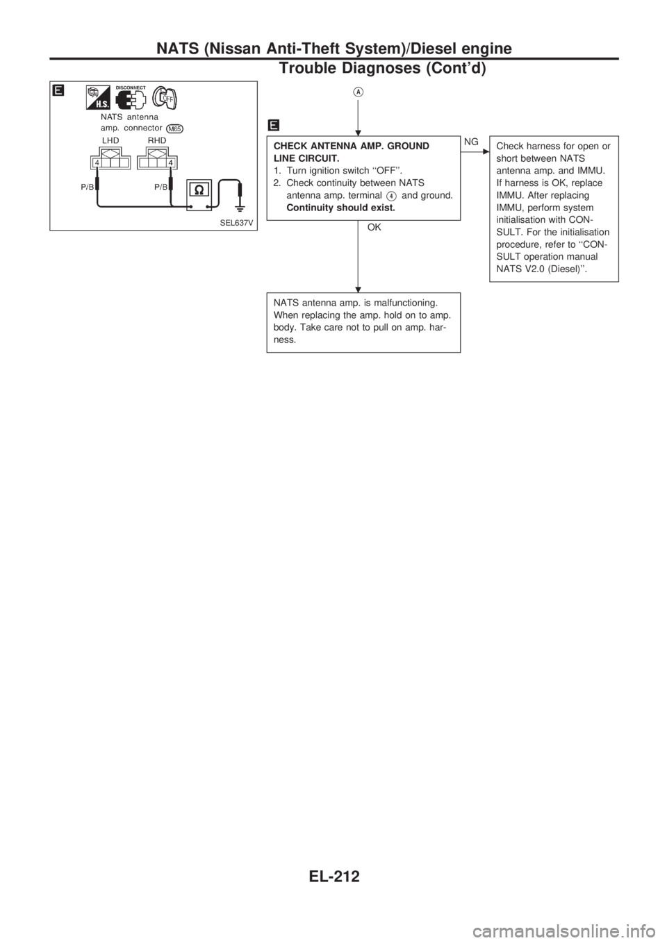
CHECK ANTENNA AMP. GROUND
LINE CIRCUIT.
1. Turn ignition switch ``OFF''.
2. Check continuity between NATS
antenna amp. terminal
V4and ground.
Continuity should exist.
OK
cNG
Check harness for open or
short between NATS
antenna amp. and IMMU.
If harness is OK, replace
IMMU. After replacing
IMMU, perform system
initialisation with CON-
SULT. For the initialisation
procedure, refer to ``CON-
SULT operation manual
NATS V2.0 (Diesel)''.
NATS antenna amp. is malfunctioning.
When replacing the amp. hold on to amp.
body. Take care not to pull on amp. har-
ness.
SEL637V
.
.
NATS (Nissan Anti-Theft System)/Diesel engine
Trouble Diagnoses (Cont'd)
EL-212
Page 1511 of 1659
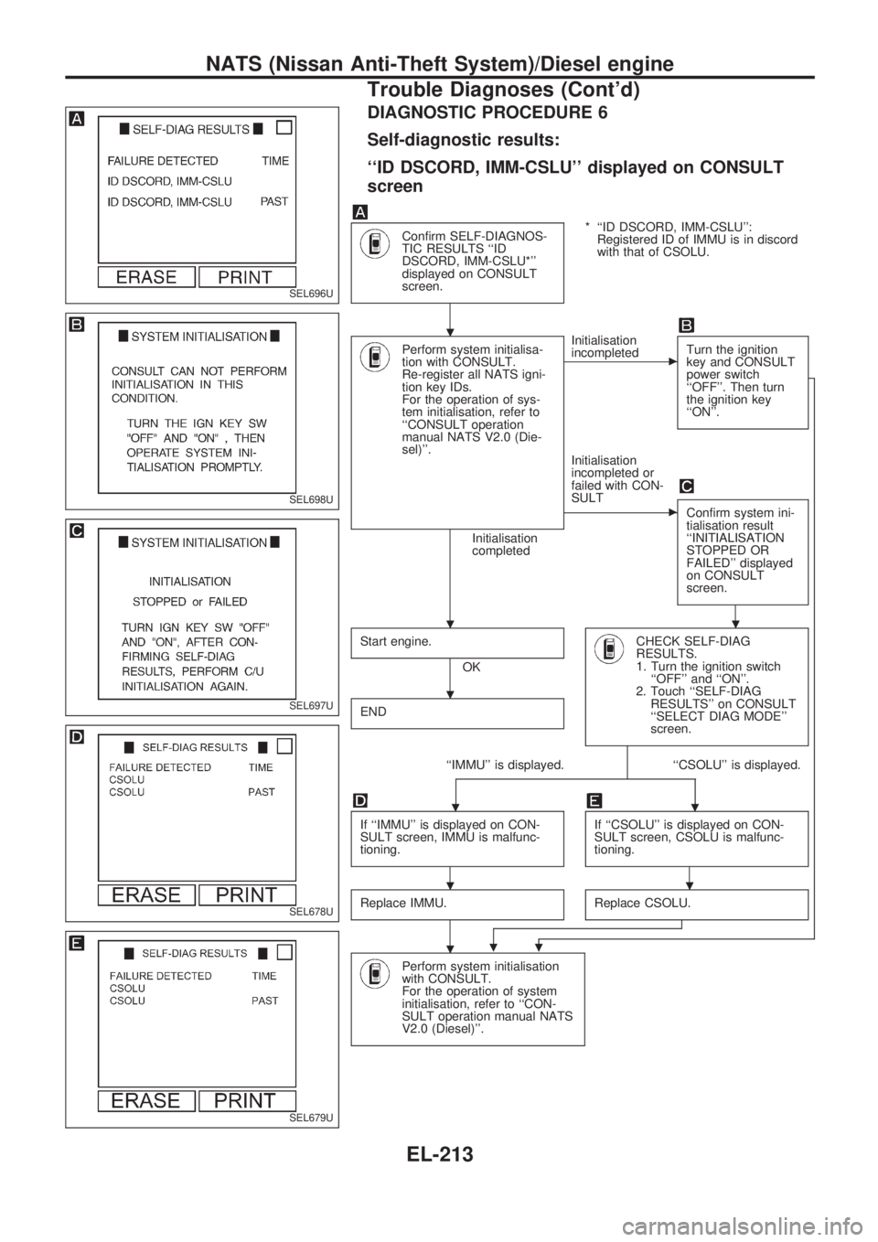
DIAGNOSTIC PROCEDURE 6
Self-diagnostic results:
``ID DSCORD, IMM-CSLU'' displayed on CONSULT
screen
Confirm SELF-DIAGNOS-
TIC RESULTS ``ID
DSCORD, IMM-CSLU*''
displayed on CONSULT
screen.* ``ID DSCORD, IMM-CSLU'':
Registered ID of IMMU is in discord
with that of CSOLU.
Perform system initialisa-
tion with CONSULT.
Re-register all NATS igni-
tion key IDs.
For the operation of sys-
tem initialisation, refer to
``CONSULT operation
manual NATS V2.0 (Die-
sel)''.
Initialisation
completedInitialisation
incompleted
cTurn the ignition
key and CONSULT
power switch
``OFF''. Then turn
the ignition key
``ON''.
Initialisation
incompleted or
failed with CON-
SULT
cConfirm system ini-
tialisation result
``INITIALISATION
STOPPED OR
FAILED'' displayed
on CONSULT
screen.
Start engine.
OK
CHECK SELF-DIAG
RESULTS.
1. Turn the ignition switch
``OFF'' and ``ON''.
2. Touch ``SELF-DIAG
RESULTS'' on CONSULT
``SELECT DIAG MODE''
screen.
END
``IMMU'' is displayed. ``CSOLU'' is displayed.
..
If ``IMMU'' is displayed on CON-
SULT screen, IMMU is malfunc-
tioning.If ``CSOLU'' is displayed on CON-
SULT screen, CSOLU is malfunc-
tioning.
Replace IMMU.Replace CSOLU.
..
Perform system initialisation
with CONSULT.
For the operation of system
initialisation, refer to ``CON-
SULT operation manual NATS
V2.0 (Diesel)''.
SEL696U
SEL698U
SEL697U
SEL678U
SEL679U
.
..
.
..
.
NATS (Nissan Anti-Theft System)/Diesel engine
Trouble Diagnoses (Cont'd)
EL-213
Page 1512 of 1659
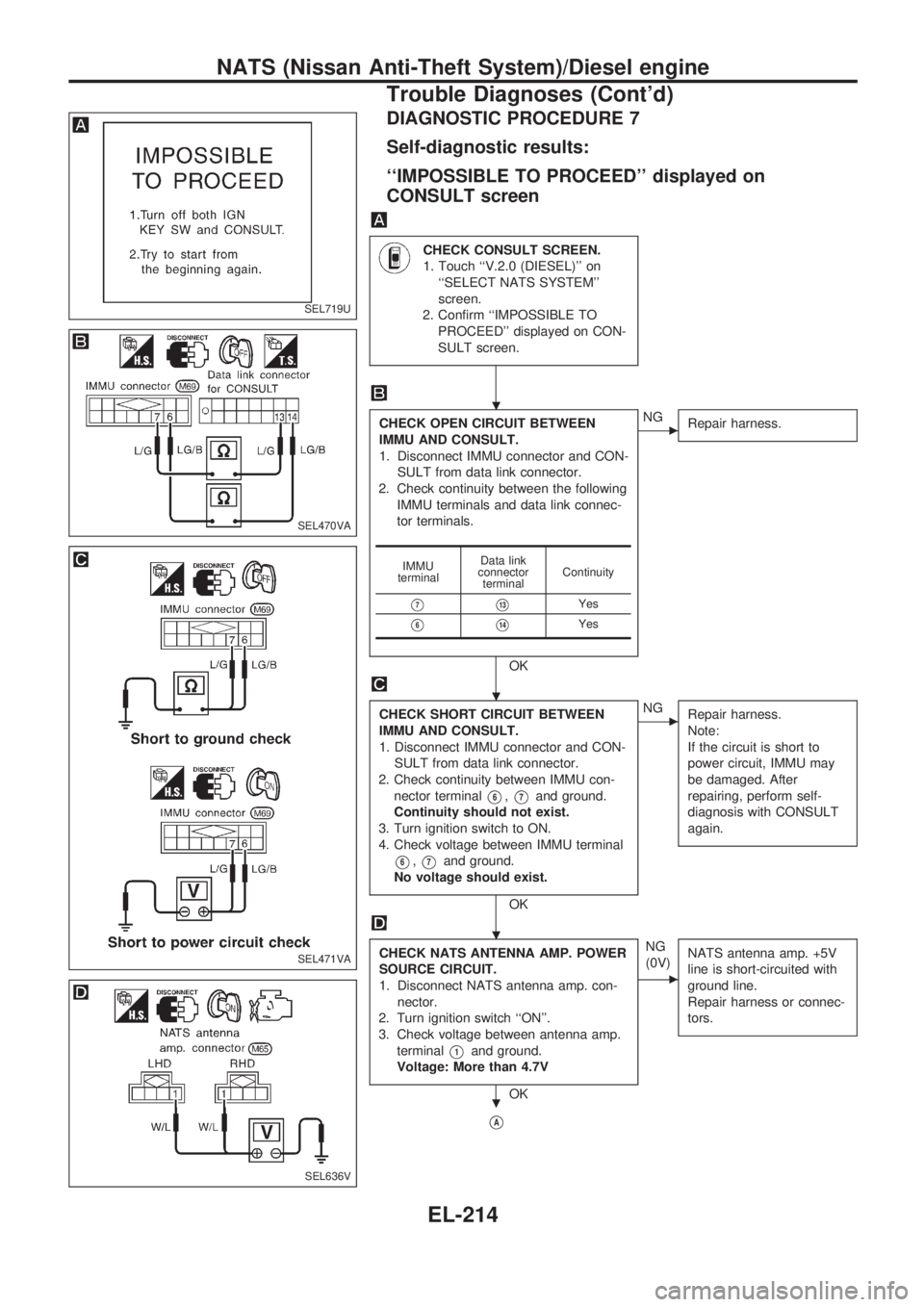
DIAGNOSTIC PROCEDURE 7
Self-diagnostic results:
``IMPOSSIBLE TO PROCEED'' displayed on
CONSULT screen
CHECK CONSULT SCREEN.
1. Touch ``V.2.0 (DIESEL)'' on
``SELECT NATS SYSTEM''
screen.
2. Confirm ``IMPOSSIBLE TO
PROCEED'' displayed on CON-
SULT screen.
CHECK OPEN CIRCUIT BETWEEN
IMMU AND CONSULT.
1. Disconnect IMMU connector and CON-
SULT from data link connector.
2. Check continuity between the following
IMMU terminals and data link connec-
tor terminals.
OK
cNG
Repair harness.
CHECK SHORT CIRCUIT BETWEEN
IMMU AND CONSULT.
1. Disconnect IMMU connector and CON-
SULT from data link connector.
2. Check continuity between IMMU con-
nector terminal
V6,V7and ground.
Continuity should not exist.
3. Turn ignition switch to ON.
4. Check voltage between IMMU terminal
V6,V7and ground.
No voltage should exist.
OK
cNG
Repair harness.
Note:
If the circuit is short to
power circuit, IMMU may
be damaged. After
repairing, perform self-
diagnosis with CONSULT
again.
CHECK NATS ANTENNA AMP. POWER
SOURCE CIRCUIT.
1. Disconnect NATS antenna amp. con-
nector.
2. Turn ignition switch ``ON''.
3. Check voltage between antenna amp.
terminal
V1and ground.
Voltage: More than 4.7V
OKNG
(0V)
c
NATS antenna amp. +5V
line is short-circuited with
ground line.
Repair harness or connec-
tors.
VA
IMMU
terminalData link
connector
terminalContinuity
V7V13Yes
V6V14Yes
SEL719U
SEL470VA
SEL471VA
SEL636V
.
.
.
.
NATS (Nissan Anti-Theft System)/Diesel engine
Trouble Diagnoses (Cont'd)
EL-214
Page 1551 of 1659
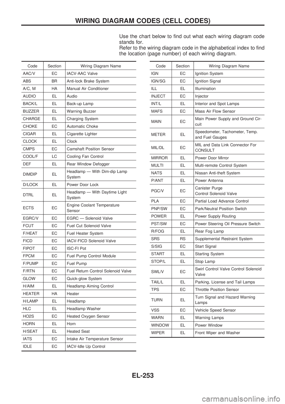
Use the chart below to find out what each wiring diagram code
stands for.
Refer to the wiring diagram code in the alphabetical index to find
the location (page number) of each wiring diagram.
Code Section Wiring Diagram Name
AAC/V EC IACV-AAC Valve
ABS BR Anti-lock Brake System
A/C, M HA Manual Air Conditioner
AUDIO EL Audio
BACK/L EL Back-up Lamp
BUZZER EL Warning Buzzer
CHARGE EL Charging System
CHOKE EC Automatic Choke
CIGAR EL Cigarette Lighter
CLOCK EL Clock
CMPS EC Camshaft Position Sensor
COOL/F LC Cooling Fan Control
DEF EL Rear Window Defogger
DIMDIP ELHeadlamp Ð With Dim-dip Lamp
System
D/LOCK EL Power Door Lock
DTRL ELHeadlamp Ð With Daytime Light
System
ECTS ECEngine Coolant Temperature
Sensor
EGRC/V EC EGRC Ð Solenoid Valve
FCUT EC Fuel Cut Solenoid Valve
F/HEAT EC Fuel Heater System
FICD EC IACV-FICD Solenoid Valve
FIPOT EC ISC-FI Pot
FPCM EC Fuel Pump Control Module
F/PUMP EC Fuel Pump
F/RTN EC Fuel Return Control Solenoid Valve
GLOW EC Quick-glow System
H/AIM EL Headlamp Aiming Control
HEATER HA Heater
H/LAMP EL Headlamp
HLC EL Headlamp Washer
HO2S EC Heated Oxygen Sensor
HORN EL Horn
H/SEAT EL Heated Seat
IATS EC Intake Air Temperature Sensor
IDLE EC IACV-Idle Up ControlCode Section Wiring Diagram Name
IGN EC Ignition System
IGN/SG EC Ignition Signal
ILL EL Illumination
INJECT EC Injector
INT/L EL Interior and Spot Lamps
MAFS EC Mass Air Flow Sensor
MAIN ECMain Power Supply and Ground Cir-
cuit
METER ELSpeedometer, Tachometer, Temp.
and Fuel Gauges
MIL/DL ECMIL and Data Link Connector For
CONSULT
MIRROR EL Power Door Mirror
MULTI EL Multi-remote Control System
NATS EL Nissan Anti-theft System
P/ANT EL Power Antenna
PGC/V ECCanister Purge
Control Solenoid Valve
PLA EC Partial Load Advance Control
PNP/SW EC Park/Neutral Position Switch
POWER EL Power Supply Routing
PST/SW EC Power Steering Oil Pressure Switch
R/FOG EL Rear Fog Lamp
SRS RS Supplemental Restraint System
S/SIG EC Start Signal
START EL Starting System
STOP/L EL Stop Lamp
SWL/V ECSwirl Control Valve Control Solenoid
Valve
TAIL/L EL Parking, License and Tail Lamps
TPS EC Throttle Position Sensor
TURN ELTurn Signal and Hazard Warning
Lamps
VSS EC Vehicle Speed Sensor
WARN EL Warning Lamps
WINDOW EL Power Window
WIPER EL Front Wiper and Washer
WIRING DIAGRAM CODES (CELL CODES)
EL-253