Page 371 of 1659
Engine revolution sensor
1. Disconnect engine revolution sensor harness connector.
2. Check resistance between terminals
V1andV2.
Resistance: Approximately 1.6 kW[at 25ÉC (77ÉF)]
If NG, replace sensor.
Potentiometer
1. Disconnect potentiometer harness connector.
2. Make sure that resistance between terminals
V2andV3
changes when accelerator operated.
Accelerator pedal condition Resistance kW[at 20ÉC (68ÉF)]
Completely released Approximately 0.7
Partially depressed 0.7 - 5
Completely depressed Approximately 5
If NG, replace potentiometer.
Atmospheric pressure sensor
This sensor is inside ECM and not replaceable.
EGR system should not operate under atmospheric pressure
below 90.0 kPa (900 mbar, 675 mmHg, 26.57 inHg).
Engine coolant temperature sensor
Refer to ``Component Inspection'' in ``QUICK-GLOW SYSTEM'',
EC-209.
DEC031
DEC032
EGR SYSTEMTD
Component Inspection (Cont'd)
EC-219
Page 655 of 1659

Measurement of Compression Pressure
1. Warm up engine.
2. Turn ignition switch OFF.
3. Release fuel pressure.
Refer to EC section (``Fuel Pressure Release'', ``BASIC SER-
VICE PROCEDURE'').
4. Remove all spark plugs.
5. Disconnect distributor center cable.
6. Attach a compression tester to No. 1 cylinder.
7. Depress accelerator pedal fully to keep throttle valve wide
open.
8. Crank engine and record highest gauge indication.
9. Repeat the measurement on each cylinder.
lAlways use a fully-charged battery to obtain specified
engine speed.
Compression pressure:
kPa (bar, kg/cm
2, psi)/rpm
Standard
1,324 (13.24, 13.5, 192)/300
Minimum
981 (9.8, 10, 142)/300
Difference limit between cylinders
98 (0.98, 1.0, 14)/300
10. If compression in one or more cylinders is low:
a. Pour a small amount of engine oil into cylinders through
spark plug holes.
b. Retest compression.
lIf adding oil helps compression, piston rings may be
worn or damaged. If so, replace piston rings after check-
ing piston.
lIf pressure stays low, a valve may be sticking or seating
improperly. Inspect and repair valve and valve seat.
(Refer to SDS.) If valve or valve seat is damaged
excessively, replace them.
lIf compression stays low in two cylinders that are next
to each other:
a. The cylinder head gasket may be leaking, or
b. Both cylinders may have valve component damage.
Inspect and repair as necessary.
SEM113B
COMPRESSION PRESSUREKA
EM-10
Page 670 of 1659

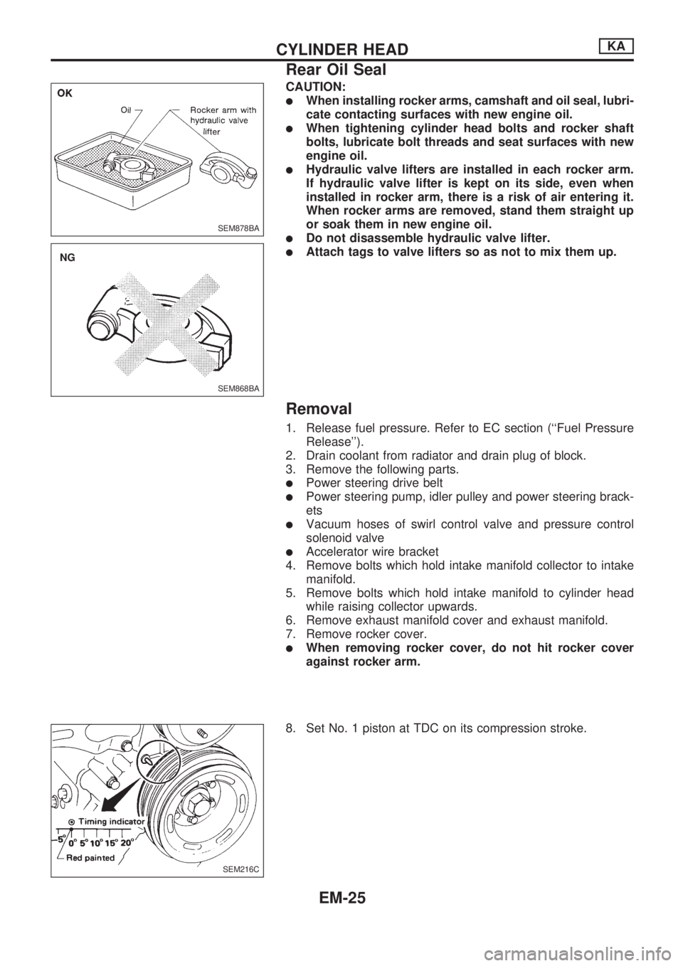
CAUTION:
lWhen installing rocker arms, camshaft and oil seal, lubri-
cate contacting surfaces with new engine oil.
lWhen tightening cylinder head bolts and rocker shaft
bolts, lubricate bolt threads and seat surfaces with new
engine oil.
lHydraulic valve lifters are installed in each rocker arm.
If hydraulic valve lifter is kept on its side, even when
installed in rocker arm, there is a risk of air entering it.
When rocker arms are removed, stand them straight up
or soak them in new engine oil.
lDo not disassemble hydraulic valve lifter.
lAttach tags to valve lifters so as not to mix them up.
Removal
1. Release fuel pressure. Refer to EC section (``Fuel Pressure
Release'').
2. Drain coolant from radiator and drain plug of block.
3. Remove the following parts.
lPower steering drive belt
lPower steering pump, idler pulley and power steering brack-
ets
lVacuum hoses of swirl control valve and pressure control
solenoid valve
lAccelerator wire bracket
4. Remove bolts which hold intake manifold collector to intake
manifold.
5. Remove bolts which hold intake manifold to cylinder head
while raising collector upwards.
6. Remove exhaust manifold cover and exhaust manifold.
7. Remove rocker cover.
lWhen removing rocker cover, do not hit rocker cover
against rocker arm.
8. Set No. 1 piston at TDC on its compression stroke.
SEM878BA
SEM868BA
.NG
SEM216C
CYLINDER HEADKA
Rear Oil Seal
EM-25
Page 681 of 1659
WARNING:
lPosition vehicle on a flat and solid surface.
lPlace chocks at front and back of rear wheels.
lDo not remove engine until exhaust system has com-
pletely cooled off.
Otherwise, you may burn yourself and/or fire may break
out in fuel line.
lBefore disconnecting fuel hose, release fuel pressure.
Refer to EC section (``Fuel Pressure Release'').
lBe sure to hoist engine and transmission in a safe man-
ner.
lFor engines not equipped with engine slingers, attach
proper slingers and bolts described in PARTS CATA-
LOG.
CAUTION:
lWhen lifting engine, be sure to clear surrounding parts.
Take special care near accelerator wire casing, brake
lines and brake master cylinder.
lIn lifting the engine, always use engine slingers in a safe
manner.
lFor 4WD models, apply sealant between engine and
transmission. Refer to MT section (``Removal and Instal-
lation'').
SEM601FA
ENGINE REMOVALKA
EM-36
Page 682 of 1659

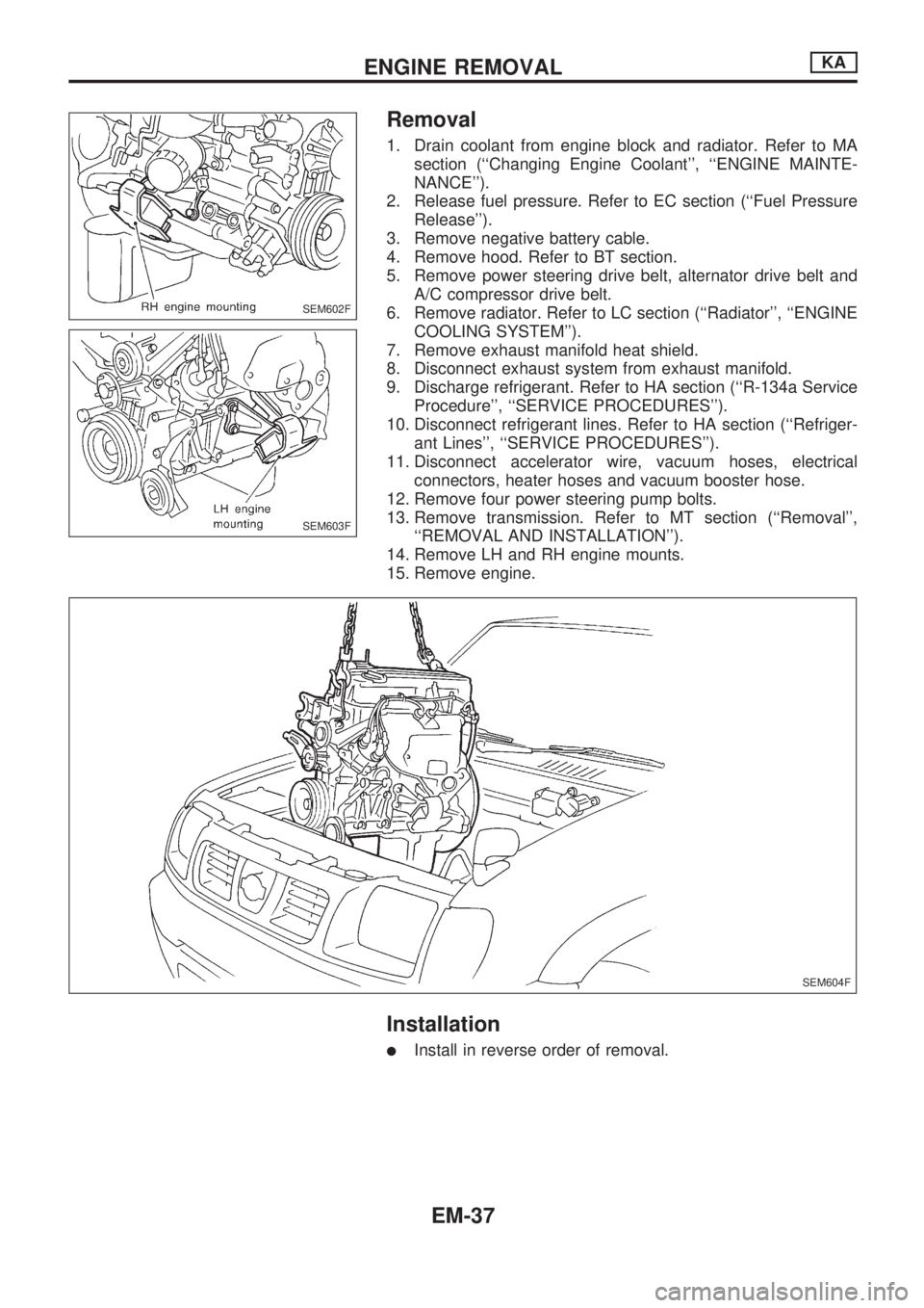
Removal
1. Drain coolant from engine block and radiator. Refer to MA
section (``Changing Engine Coolant'', ``ENGINE MAINTE-
NANCE'').
2. Release fuel pressure. Refer to EC section (``Fuel Pressure
Release'').
3. Remove negative battery cable.
4. Remove hood. Refer to BT section.
5. Remove power steering drive belt, alternator drive belt and
A/C compressor drive belt.
6. Remove radiator. Refer to LC section (``Radiator'', ``ENGINE
COOLING SYSTEM'').
7. Remove exhaust manifold heat shield.
8. Disconnect exhaust system from exhaust manifold.
9. Discharge refrigerant. Refer to HA section (``R-134a Service
Procedure'', ``SERVICE PROCEDURES'').
10. Disconnect refrigerant lines. Refer to HA section (``Refriger-
ant Lines'', ``SERVICE PROCEDURES'').
11. Disconnect accelerator wire, vacuum hoses, electrical
connectors, heater hoses and vacuum booster hose.
12. Remove four power steering pump bolts.
13. Remove transmission. Refer to MT section (``Removal'',
``REMOVAL AND INSTALLATION'').
14. Remove LH and RH engine mounts.
15. Remove engine.
Installation
lInstall in reverse order of removal.
SEM602F
SEM603F
SEM604F
ENGINE REMOVALKA
EM-37
Page 697 of 1659

Removal
Removal order and pointsApplied model
2WD 4WD
1 Remove undercover.jj
2 Drain engine oil.jj
3Remove front propeller shaft
from front differential carrier.Ðj
4Remove front drive shaft fix-
ing bolts (RH & LH).Ðj
5Remove front suspension
crossmember.jj
6Remove differential front
mounting bolts (RH & LH)
and rear mounting bolts.Ðj
7Remove front differential car-
rier.ÐjRemoval order and pointsApplied model
2WD 4WD
8Remove front differential car-
rier mounting bracket.Ðj
9Remove transmission to rear
engine mounting bracket
nuts (RH & LH).jj
10Remove engine mounting
bolts or nuts (RH & LH).jj
11Lift up engine.
If necessary, disconnect
exhaust tube.jj
12 Remove oil pan.jj
WARNING:
lPlace vehicle on a flat and solid surface.
lPlace chocks at front and rear of rear wheels.
lYou should not remove oil pan until exhaust system and
cooling system have completely cooled off.
Otherwise, you may burn yourself and/or fire may break
out in the fuel line.
lWhen removing front and/or rear engine mounting bolts
or nuts, lift up slightly engine for safety work.
CAUTION:
lIn lifting engine, be careful not to hit against adjacent
parts, especially against accelerator wire casing end,
brake tube and brake master cylinder.
lFor tightening torque, refer to EM-71, MT and PD sec-
tions.
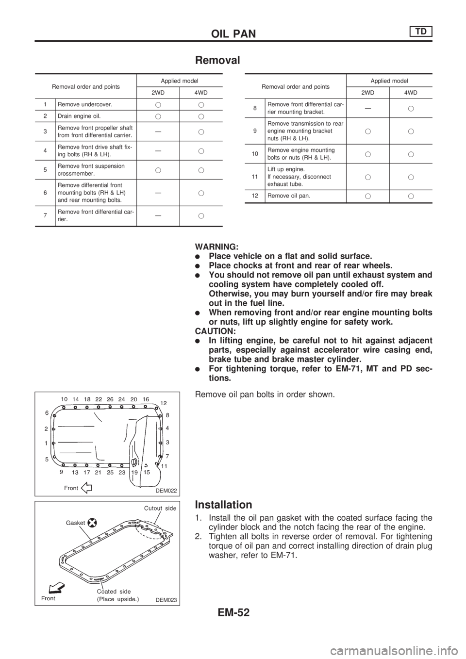
Remove oil pan bolts in order shown.
Installation
1. Install the oil pan gasket with the coated surface facing the
cylinder block and the notch facing the rear of the engine.
2. Tighten all bolts in reverse order of removal. For tightening
torque of oil pan and correct installing direction of drain plug
washer, refer to EM-71.
DEM022
DEM023
OIL PANTD
EM-52
Page 714 of 1659
WARNING:
lPosition vehicle on a flat and solid surface.
lPlace chocks at front and back of rear wheels.
lDo not remove engine until exhaust system has com-
pletely cooled off.
Otherwise, you may burn yourself and/or fire may break
out in fuel line.
lBe sure to hoist engine and transmission in a safe man-
ner.
lFor engines not equipped with engine slingers, attach
proper slingers and bolts described in PARTS CATA-
LOG.
CAUTION:
lWhen lifting engine, be sure to clear surrounding parts.
Take special care near accelerator wire casing, brake
lines and brake master cylinder.
lIn lifting the engine, always use engine slingers in a safe
manner.
lFor 4WD models, apply sealant between engine and
transmission. Refer to MT section (``Removal and Instal-
lation'').
SEM613FN
ENGINE REMOVALTD
EM-69
Page 756 of 1659
ACCELERATOR CONTROL, FUEL &
EXHAUST SYSTEMS
SECTIONFE
CONTENTS
PREPARATION/ACCELERATOR CONTROL
SYSTEM..................................................................... 1
Special Service Tool .............................................. 1
Accelerator Control System ................................... 1Adjusting Accelerator Wire .................................... 2
FUEL SYSTEM.......................................................... 3
EXHAUST SYSTEM.................................................. 5
FE