Page 1 of 1659
GENERAL INFORMATIONGI
MAINTENANCEMA
ENGINE MECHANICALEM
ENGINE LUBRICATION &
COOLING SYSTEMSLC
ENGINE CONTROL SYSTEMEC
ACCELERATOR CONTROL, FUEL &
EXHAUST SYSTEMSFE
CLUTCHCL
MANUAL TRANSAXLEMT
TRANSFERTF
PROPELLER SHAFT &
DIFFERENTIAL CARRIERPD
FRONT AXLE & FRONT SUSPENSIONFA
REAR AXLE & REAR SUSPENSIONRA
BRAKE SYSTEMBR
STEERING SYSTEMST
RESTRAINT SYSTEMRS
BODY & TRIMBT
HEATER & AIR CONDITIONERHA
ELECTRICAL SYSTEMEL
ALPHABETICAL INDEXIDX
PICKUP
MODEL D22 SERIES
Edition: February 1998
Printing: May 1998 (01)
Publication No.: SM8E-0D22E0E
NISSAN EUROPE S.A.S.
1998 NISSAN EUROPE S.A.S. Printed in the Netherlands
Not to be reproduced in whole or in part without the prior written permission of Nissan Europe S.A.S., Paris, France.
QUICK REFERENCE INDEX
Page 170 of 1659

Air Conditioning Cut Control
INPUT/OUTPUT SIGNAL LINE
Air conditioner switchcAir conditioner ``ON'' signal
ECM
(ECCS
control
module)
cAir condi-
tioner
relayThrottle position sensorcThrottle valve opening angle
Ignition switch
cStart signal
Engine coolant temperature sensor
cEngine coolant temperature
SYSTEM DESCRIPTION
This system improves engine operation when the
air conditioner is used.
Under the following conditions, the air conditioner
is turned off.
lWhen the accelerator pedal is fully depressed
lWhen cranking the engine
lWhen the engine coolant temperature becomes
excessively high
Fuel Cut Control (at no load & high engine
speed)
INPUT/OUTPUT SIGNAL LINE
Vehicle speed sensorcVehicle speed
ECM
(ECCS
control
module)
cInjectors
Neutral position switchcNeutral position
Throttle position sensor
cThrottle position
Engine coolant temperature sensor
cEngine coolant temperature
Camshaft position sensor
cEngine speed
If the engine speed is above 3,500 rpm with no load (for
example, in neutral and engine speed over 3,500 rpm) fuel will
be cut off after some time. The exact time when the fuel is cut
off varies based on engine speed.
Fuel cut will operate until the engine speed reaches 1,500 rpm,
then fuel cut is cancelled.
NOTE:
This function is different than deceleration control listed
under multiport fuel injection on EC-14.
ENGINE AND EMISSION BASIC CONTROL SYSTEM DESCRIPTIONKA
EC-18
Page 222 of 1659

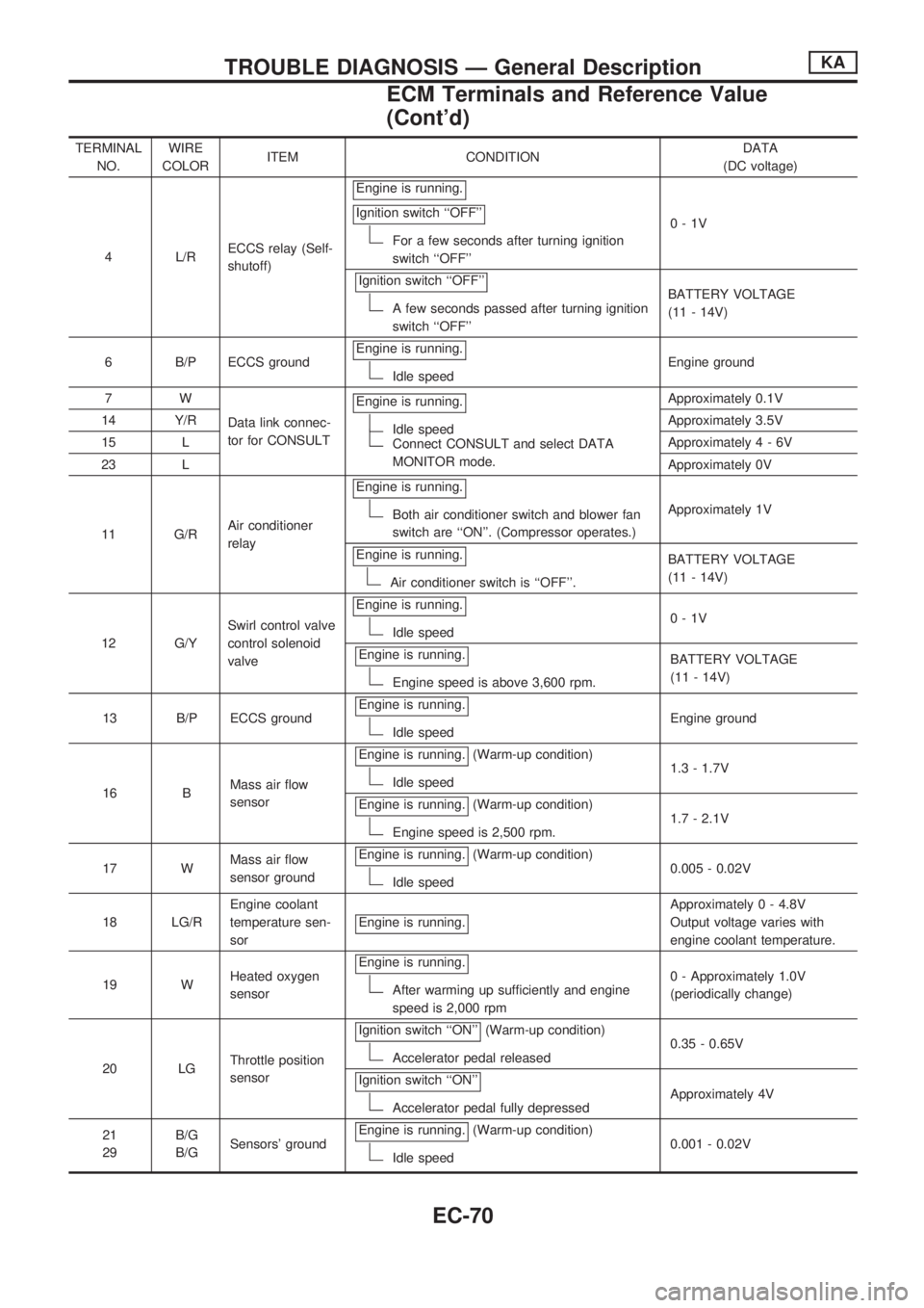
TERMINAL
NO.WIRE
COLORITEM CONDITIONDATA
(DC voltage)
4 L/RECCS relay (Self-
shutoff)Engine is running.
Ignition switch ``OFF''
For a few seconds after turning ignition
switch ``OFF''0-1V
Ignition switch ``OFF''
A few seconds passed after turning ignition
switch ``OFF''BATTERY VOLTAGE
(11 - 14V)
6 B/P ECCS groundEngine is running.
Idle speedEngine ground
7W
Data link connec-
tor for CONSULTEngine is running.
Idle speedConnect CONSULT and select DATA
MONITOR mode.Approximately 0.1V
14 Y/RApproximately 3.5V
15 LApproximately4-6V
23 LApproximately 0V
11 G/RAir conditioner
relayEngine is running.
Both air conditioner switch and blower fan
switch are ``ON''. (Compressor operates.)Approximately 1V
Engine is running.
Air conditioner switch is ``OFF''.BATTERY VOLTAGE
(11 - 14V)
12 G/YSwirl control valve
control solenoid
valveEngine is running.
Idle speed0-1V
Engine is running.
Engine speed is above 3,600 rpm.BATTERY VOLTAGE
(11 - 14V)
13 B/P ECCS groundEngine is running.
Idle speedEngine ground
16 BMass air flow
sensorEngine is running.
(Warm-up condition)
Idle speed1.3 - 1.7V
Engine is running.
(Warm-up condition)
Engine speed is 2,500 rpm.1.7 - 2.1V
17 WMass air flow
sensor groundEngine is running.
(Warm-up condition)
Idle speed0.005 - 0.02V
18 LG/REngine coolant
temperature sen-
sorEngine is running.
Approximately 0 - 4.8V
Output voltage varies with
engine coolant temperature.
19 WHeated oxygen
sensorEngine is running.
After warming up sufficiently and engine
speed is 2,000 rpm0 - Approximately 1.0V
(periodically change)
20 LGThrottle position
sensorIgnition switch ``ON''
(Warm-up condition)
Accelerator pedal released0.35 - 0.65V
Ignition switch ``ON''
Accelerator pedal fully depressedApproximately 4V
21
29B/G
B/GSensors' groundEngine is running.
(Warm-up condition)
Idle speed0.001 - 0.02V
TROUBLE DIAGNOSIS Ð General DescriptionKA
ECM Terminals and Reference Value
(Cont'd)
EC-70
Page 265 of 1659

Throttle Position Sensor
COMPONENT DESCRIPTION
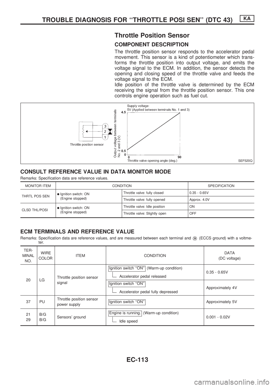
The throttle position sensor responds to the accelerator pedal
movement. This sensor is a kind of potentiometer which trans-
forms the throttle position into output voltage, and emits the
voltage signal to the ECM. In addition, the sensor detects the
opening and closing speed of the throttle valve and feeds the
voltage signal to the ECM.
Idle position of the throttle valve is determined by the ECM
receiving the signal from the throttle position sensor. This one
controls engine operation such as fuel cut.
CONSULT REFERENCE VALUE IN DATA MONITOR MODE
Remarks: Specification data are reference values.
MONITOR ITEM CONDITION SPECIFICATION
THRTL POS SEN
lIgnition switch: ON
(Engine stopped)Throttle valve: fully closed 0.35 - 0.65V
Throttle valve: fully opened Approx. 4.0V
CLSD THL/POSI
lIgnition switch: ON
(Engine stopped)Throttle valve: Idle position ON
Throttle valve: Slightly open OFF
ECM TERMINALS AND REFERENCE VALUE
Remarks: Specification data are reference values, and are measured between each terminal andV39(ECCS ground) with a voltme-
ter.
TER-
MINAL
NO.WIRE
COLORITEM CONDITIONDATA
(DC voltage)
20 LGThrottle position sensor
signalIgnition switch ``ON''
(Warm-up condition)
Accelerator pedal released0.35 - 0.65V
Ignition switch ``ON''
Accelerator pedal fully depressedApproximately 4V
37 PUThrottle position sensor
power supplyIgnition switch ``ON''
Approximately 5V
21
29B/G
B/GSensors' groundEngine is running.
(Warm-up condition)
Idle speed0.001 - 0.02V
SEF520Q
TROUBLE DIAGNOSIS FOR ``THROTTLE POSI SEN'' (DTC 43)KA
EC-113
Page 335 of 1659

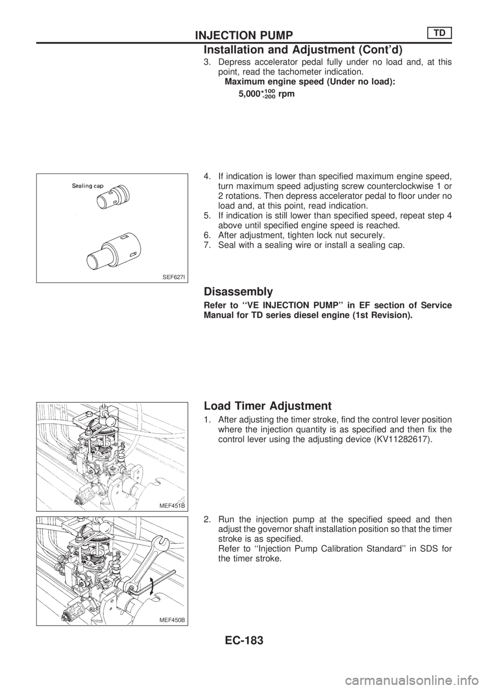
3. Depress accelerator pedal fully under no load and, at this
point, read the tachometer indication.
Maximum engine speed (Under no load):
5,000
+100
-200rpm
4. If indication is lower than specified maximum engine speed,
turn maximum speed adjusting screw counterclockwise 1 or
2 rotations. Then depress accelerator pedal to floor under no
load and, at this point, read indication.
5. If indication is still lower than specified speed, repeat step 4
above until specified engine speed is reached.
6. After adjustment, tighten lock nut securely.
7. Seal with a sealing wire or install a sealing cap.
Disassembly
Refer to ``VE INJECTION PUMP'' in EF section of Service
Manual for TD series diesel engine (1st Revision).
Load Timer Adjustment
1. After adjusting the timer stroke, find the control lever position
where the injection quantity is as specified and then fix the
control lever using the adjusting device (KV11282617).
2. Run the injection pump at the specified speed and then
adjust the governor shaft installation position so that the timer
stroke is as specified.
Refer to ``Injection Pump Calibration Standard'' in SDS for
the timer stroke.
SEF627I
MEF451B
MEF450B
INJECTION PUMPTD
Installation and Adjustment (Cont'd)
EC-183
Page 670 of 1659

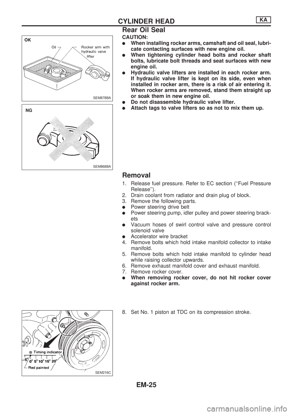
CAUTION:
lWhen installing rocker arms, camshaft and oil seal, lubri-
cate contacting surfaces with new engine oil.
lWhen tightening cylinder head bolts and rocker shaft
bolts, lubricate bolt threads and seat surfaces with new
engine oil.
lHydraulic valve lifters are installed in each rocker arm.
If hydraulic valve lifter is kept on its side, even when
installed in rocker arm, there is a risk of air entering it.
When rocker arms are removed, stand them straight up
or soak them in new engine oil.
lDo not disassemble hydraulic valve lifter.
lAttach tags to valve lifters so as not to mix them up.
Removal
1. Release fuel pressure. Refer to EC section (``Fuel Pressure
Release'').
2. Drain coolant from radiator and drain plug of block.
3. Remove the following parts.
lPower steering drive belt
lPower steering pump, idler pulley and power steering brack-
ets
lVacuum hoses of swirl control valve and pressure control
solenoid valve
lAccelerator wire bracket
4. Remove bolts which hold intake manifold collector to intake
manifold.
5. Remove bolts which hold intake manifold to cylinder head
while raising collector upwards.
6. Remove exhaust manifold cover and exhaust manifold.
7. Remove rocker cover.
lWhen removing rocker cover, do not hit rocker cover
against rocker arm.
8. Set No. 1 piston at TDC on its compression stroke.
SEM878BA
SEM868BA
.NG
SEM216C
CYLINDER HEADKA
Rear Oil Seal
EM-25
Page 756 of 1659
ACCELERATOR CONTROL, FUEL &
EXHAUST SYSTEMS
SECTIONFE
CONTENTS
PREPARATION/ACCELERATOR CONTROL
SYSTEM..................................................................... 1
Special Service Tool .............................................. 1
Accelerator Control System ................................... 1Adjusting Accelerator Wire .................................... 2
FUEL SYSTEM.......................................................... 3
EXHAUST SYSTEM.................................................. 5
FE
Page 757 of 1659
Special Service Tool
Tool number
Tool nameDescription
KV10114400
Heated oxygen sensor
wrench
NT636
Loosening or tightening heated oxygen sen-
sor
a = 22 mm (0.87 in)
Accelerator Control System
CAUTION:
lWhen removing accelerator wire, make a mark to indicate lock nut's initial position.
lCheck that throttle valve opens fully when accelerator pedal is fully depressed. Also check that
it returns to idle position when pedal is released.
lCheck accelerator control parts for improper contact with any adjacent parts.
lWhen connecting accelerator wire, be careful not to twist or scratch wire.
SFE454A
PREPARATION/ACCELERATOR CONTROL SYSTEM
FE-1