Page 89 of 128

SYSTEM DESCRIPTION
Component parts
Fan speed control system components are:
1) Auto amp.
2) Fan control amp.
3) A/C LAN system (PBR built in mode door motor and air mix door motor)
4) In-vehicle sensor
5) Ambient sensor
6) Sunload sensor
7) Intake sensor
System operation
Automatic mode
In the automatic mode, the blower motor speed is calculated by the automatic ampli®er based on inputs from
the PBR, in-vehicle sensor, sunload sensor, intake sensor and ambient sensor. The blower motor applied
voltage ranges from approximately 5 volts (lowest speed) to 12 volts (highest speed).
The control blower speed (in the range of 5 to 12V), the automatic ampli®er supplies a gate voltage to the fan
control ampli®er. Based on this voltage, the fan control ampli®er controls the voltage supplied to the blower
motor.
Starting fan speed control
Start up from ``COLD SOAK'' condition (Automatic mode)
In a cold start up condition where the engine coolant temperature is below 50ÉC, the blower will not operate
for a short period of time (up to 150 seconds). The exact start delay time varies depending on the ambient
and engine coolant temperature.
In the most extreme case (very low ambient) the blower starting delay will be 150 seconds as described above.
After this delay, the blower will operate at low speed until the engine coolant temperature rises above 55ÉC,
at which time the blower speed will increase to the objective speed.
Start up from normal or ``HOT SOAK'' condition (Automatic mode)
The blower will begin operation momentarily after the AUTO button is pushed. The blower speed will gradu-
ally rise to the objective speed over a time period of 3 seconds or less (actual time depends on the objective
blower speed).
SHA006FB
TROUBLE DIAGNOSESAUTO
Blower Motor (Cont'd)
HA-87
Page 99 of 128
jD
Note
Check circuit continuity between dual-pres-
sure switch harness terminal No.j
1and
thermo control amp. harness terminal No.
j
3.
Continuity should exist.
If OK, check harness for short.
Note:
If the result is NG or No after checking circuit continuity, repair harness
or connector.
COMPONENT INSPECTION
A/C relay
Check continuity between terminal Nos.j3andj5,j6andj7.
Conditions Continuity
12V direct current supply between terminal Nos.
j
1andj2Ye s
No current supply No
If NG, replace relay.
Dual-pressure switch
ON
kPa (bar, kg/cm2, psi)OFF
kPa (bar, kg/cm2, psi)
Low-pressure
sideIncreasing to
157 - 216 (1.57 - 2.16,
1.6 - 2.2, 23 - 31)Decreasing to
157 - 196 (1.57 - 1.96,
1.6 - 2.0, 23 - 28)
High-pressure
sideDecreasing to
1,863 - 2,256 (18.6 - 22.6,
19 - 23, 270 - 327)Increasing to
2,452 - 2,844 (24.5 - 28.4,
25 - 29, 356 - 412)
RHA663G
SEC202B
RHA628G
.
TROUBLE DIAGNOSESAUTO
Magnet Clutch (Cont'd)
HA-97
Page 114 of 128

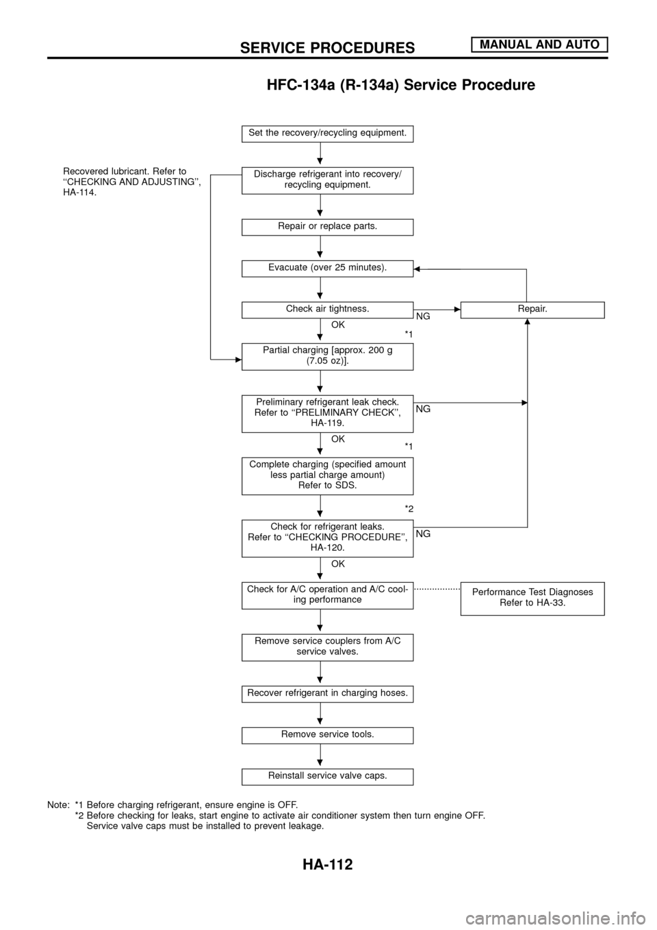
HFC-134a (R-134a) Service Procedure
Set the recovery/recycling equipment.
Recovered lubricant. Refer to
``CHECKING AND ADJUSTING'',
HA-114.
c
Discharge refrigerant into recovery/
recycling equipment.
Repair or replace parts.
Evacuate (over 25 minutes).b
Check air tightness.
OK
*1
cNGRepair.m
Partial charging [approx. 200 g
(7.05 oz)].
Preliminary refrigerant leak check.
Refer to ``PRELIMINARY CHECK'',
HA-119.
OK
*1
cNG
Complete charging (speci®ed amount
less partial charge amount)
Refer to SDS.
*2
Check for refrigerant leaks.
Refer to ``CHECKING PROCEDURE'',
HA-120.
OK
NG
Check for A/C operation and A/C cool-
ing performance..................
Performance Test Diagnoses
Refer to HA-33.
Remove service couplers from A/C
service valves.
Recover refrigerant in charging hoses.
Remove service tools.
Reinstall service valve caps.
Note: *1 Before charging refrigerant, ensure engine is OFF.
*2 Before checking for leaks, start engine to activate air conditioner system then turn engine OFF.
Service valve caps must be installed to prevent leakage.
.
.
.
.
.
.
.
.
.
.
.
.
.
SERVICE PROCEDURESMANUAL AND AUTO
HA-112
Page 116 of 128

Maintenance of Lubricant Quantity in
Compressor
The lubricant used to lubricate the compressor circulates through
the system with the refrigerant. Add lubricant to compressor when
replacing any component or after a large gas leakage occurred. It
is important to maintain the speci®ed amount.
If lubricant quantity is not maintained properly, the following mal-
functions may result:
+Lack of lubricant: May lead to a seized compressor
+Excessive lubricant: Inadequate cooling (thermal exchange
interference)
LUBRICANT
Name: Nissan A/C System Oil Type S
Part number: KLH00-PAGS0
CHECKING AND ADJUSTING
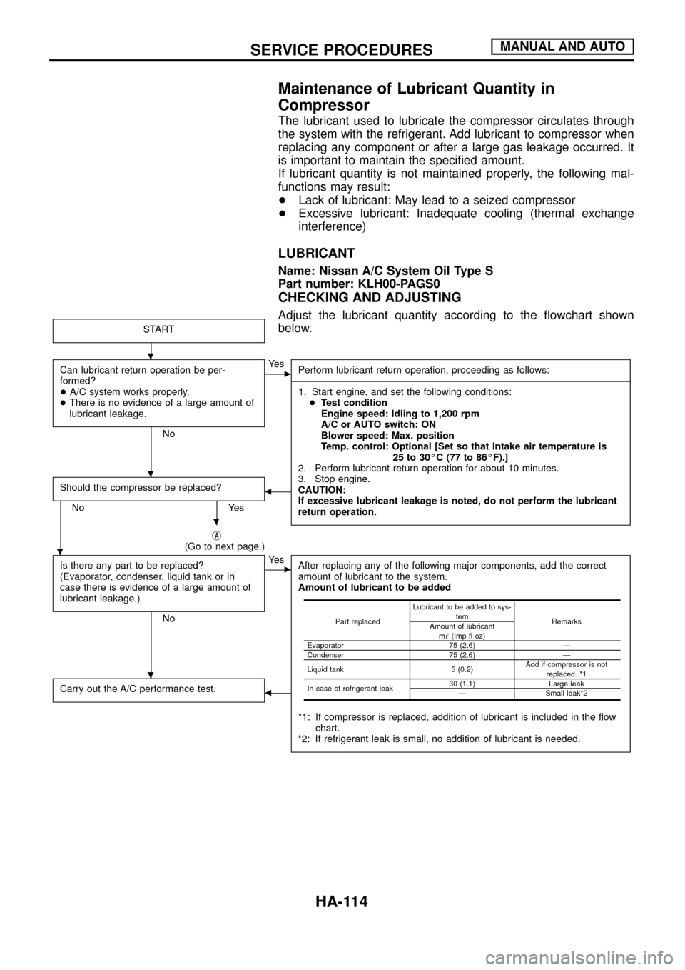
Adjust the lubricant quantity according to the ¯owchart shown
below.
START
Can lubricant return operation be per-
formed?
+A/C system works properly.
+There is no evidence of a large amount of
lubricant leakage.
No
cYe s
Perform lubricant return operation, proceeding as follows:
------------------------------------------------------------------------------------------------------------------------------------------------------------------------------------------------------------------------------------------------------------------------------------------------------------------------------------------------------------------------------------------------------------------------------------------------------------------------------------------------------------------------------------
1. Start engine, and set the following conditions:
+Test condition
Engine speed: Idling to 1,200 rpm
A/C or AUTO switch: ON
Blower speed: Max. position
Temp. control: Optional [Set so that intake air temperature is
25 to 30ÉC (77 to 86ÉF).]
2. Perform lubricant return operation for about 10 minutes.
3. Stop engine.
CAUTION:
If excessive lubricant leakage is noted, do not perform the lubricant
return operation.
Should the compressor be replaced?
No Yes
b
jA(Go to next page.)
Is there any part to be replaced?
(Evaporator, condenser, liquid tank or in
case there is evidence of a large amount of
lubricant leakage.)
No
cYe s
After replacing any of the following major components, add the correct
amount of lubricant to the system.
Amount of lubricant to be added
*1: If compressor is replaced, addition of lubricant is included in the ¯ow
chart.
*2: If refrigerant leak is small, no addition of lubricant is needed.
Carry out the A/C performance test.b
Part replacedLubricant to be added to sys-
tem
Remarks
Amount of lubricant
m!(Imp ¯ oz)
Evaporator 75 (2.6) Ð
Condenser 75 (2.6) Ð
Liquid tank 5 (0.2)Add if compressor is not
replaced. *1
In case of refrigerant leak30 (1.1) Large leak
Ð Small leak*2
.
.
.
.
.
SERVICE PROCEDURESMANUAL AND AUTO
HA-114
Page:
< prev 1-8 9-16 17-24