Page 37 of 128

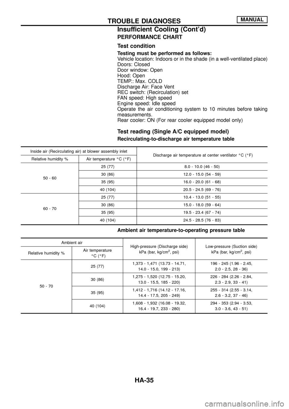
PERFORMANCE CHART
Test condition
Testing must be performed as follows:
Vehicle location: Indoors or in the shade (in a well-ventilated place)
Doors: Closed
Door window: Open
Hood: Open
TEMP.: Max. COLD
Discharge Air: Face Vent
REC switch: (Recirculation) set
FAN speed: High speed
Engine speed: Idle speed
Operate the air conditioning system to 10 minutes before taking
measurements.
Rear cooler: ON (For rear cooler equipped model only)
Test reading (Single A/C equipped model)
Recirculating-to-discharge air temperature table
Inside air (Recirculating air) at blower assembly inlet
Discharge air temperature at center ventilator ÉC (ÉF)
Relative humidity % Air temperature ÉC (ÉF)
50-6025 (77) 8.0 - 10.0 (46 - 50)
30 (86) 12.0 - 15.0 (54 - 59)
35 (95) 16.0 - 20.0 (61 - 68)
40 (104) 20.5 - 24.5 (69 - 76)
60-7025 (77) 10.4 - 13.0 (51 - 55)
30 (86) 15.0 - 18.0 (59 - 64)
35 (95) 19.5 - 23.4 (67 - 74)
40 (104) 24.5 - 28.5 (76 - 83)
Ambient air temperature-to-operating pressure table
Ambient air
High-pressure (Discharge side)
kPa (bar, kg/cm
2, psi)Low-pressure (Suction side)
kPa (bar, kg/cm2, psi)
Relative humidity %Air temperature
ÉC (ÉF)
50-7025 (77)1,373 - 1,471 (13.73 - 14.71,
14.0 - 15.0, 199 - 213)196 - 245 (1.96 - 2.45,
2.0 - 2.5, 28 - 36)
30 (86)1,275 - 1,520 (12.75 - 15.20,
13.0 - 15.5, 185 - 220)226 - 284 (2.26 - 2.84,
2.3 - 2.9, 33 - 41)
35 (95)1,412 - 1,716 (14.12 - 17.16,
14.4 - 17.5, 205 - 249)255 - 314 (2.55 - 3.14,
2.6 - 3.2, 37 - 46)
40 (104)1,608 - 1,932 (16.08 - 19.32,
16.4 - 19.7, 233 - 280)294 - 353 (2.94 - 3.53,
3.0 - 3.6, 43 - 51)
TROUBLE DIAGNOSESMANUAL
Insufficient Cooling (Cont'd)
HA-35
Page 40 of 128

Gauge indication Refrigerant cycle Probable cause Corrective action
Low-pressure side sometimes
becomes negative.
AC354A
+Air conditioner system does
not function and does not
cyclically cool the compart-
ment air.
+The system constantly func-
tions for a certain period of
time after compressor is
stopped and restarted.Refrigerant does not discharge
cyclically.
¯
Moisture is frozen at expansion
valve outlet and inlet.
¯
Water is mixed with refrigerant.+Drain water from refrigerant
or replace refrigerant.
+Replace liquid tank.
Low-pressure side becomes
negative.
AC362A
Liquid tank or front/rear side of
expansion valve's pipe is
frosted or dewed.High-pressure side is closed
and refrigerant does not ¯ow.
¯
Expansion valve or liquid tank
is frosted.Leave the system at rest. Start
it again to check whether or not
the problem is caused by water
or foreign particles.
+If water is the cause, initially
cooling is okay. Then the
water freezes, causing a
blockage. Drain water from
refrigerant or replace refriger-
ant.
+If due to foreign particles,
remove expansion valve and
remove the particles with dry
and compressed air.
+If either of the above meth-
ods cannot correct the
problem, replace expansion
valve.
+Replace liquid tank.
+Check lubricant for contami-
nation.
TROUBLE DIAGNOSESMANUAL
Trouble Diagnoses for Abnormal Pressure
(Cont'd)
HA-38
Page 49 of 128
ELECTRICAL COMPONENTS INSPECTION
A/C switch
Check continuity between terminals at each switch position.
Switch condition Terminal No.
Continuity
A/C (+) (þ)
ON
j
2j1Ye s
OFF No
A/C relay
Check continuity between terminalsj3andj5,j6andj7.
Condition Continuity
12V direct current supply between
terminalsj
1andj2Ye s
No current supply No
Dual-pressure switch
ON
kPa (bar, kg/cm2, psi)OFF
kPa (bar, kg/cm2, psi)
Low-pressure sideIncreasing to 157 - 216
(1.57 - 2.16, 1.6 - 2.2,
23 - 31)Decreasing to 157 - 196
(1.57 - 1.96, 1.6 - 2.0,
23 - 28)
High-pressure sideDecreasing to 1,863 -
2,256 (18.6 - 22.6,
19 - 23, 270 - 327)Increasing to 2,452 -
2,844 (24.5 - 28.4,
25 - 29, 356 - 412)
Thermo control amp.
Evaporator outlet air
temperature
ÉC (ÉF)Thermo amp. operation Tester
Decreasing to 0.1 - 0.9
(32 - 34)Turn OFF Approx. 12V
Increasing to 2.5 - 3.5
(37 - 38)Turn ON Approx. 0V
RHA626G
SEC202B
RHA628G
RHA736G
TROUBLE DIAGNOSESMANUAL
Magnet Clutch (Cont'd)
HA-47
Page 51 of 128

Introduction
AIR CONDITIONER LAN SYSTEM OVERVIEW CONTROL SYSTEM
The LAN system consists of auto amp., air mix door motor and mode door motor.
A con®guration of these components is shown in the diagram below.
Features
SYSTEM CONSTRUCTION (LAN)
A small network is constructed between the auto ampli®er, air mix door motor and mode door motor. The auto
ampli®er and motors are connected by data transmission lines and motor power supply lines. The LAN net-
work is built through the ground circuits of the two motors.
Addresses, motor opening angle signals, motor stop signals and error checking messages are all transmitted
through the data transmission lines connecting the auto ampli®er and two motors.
The following functions are contained in LCUs built into the air mix door motor and the mode door motor.
+Address
+Motor opening angle signals
+Data transmission
+Motor stop and drive decision
+Opening angle sensor (PBR function)
+Comparison
+Decision (Auto ampli®er indicated value and motor opening angle comparison)
RHA439G
RHA440GA
DESCRIPTIONAUTO
HA-49
Page 64 of 128

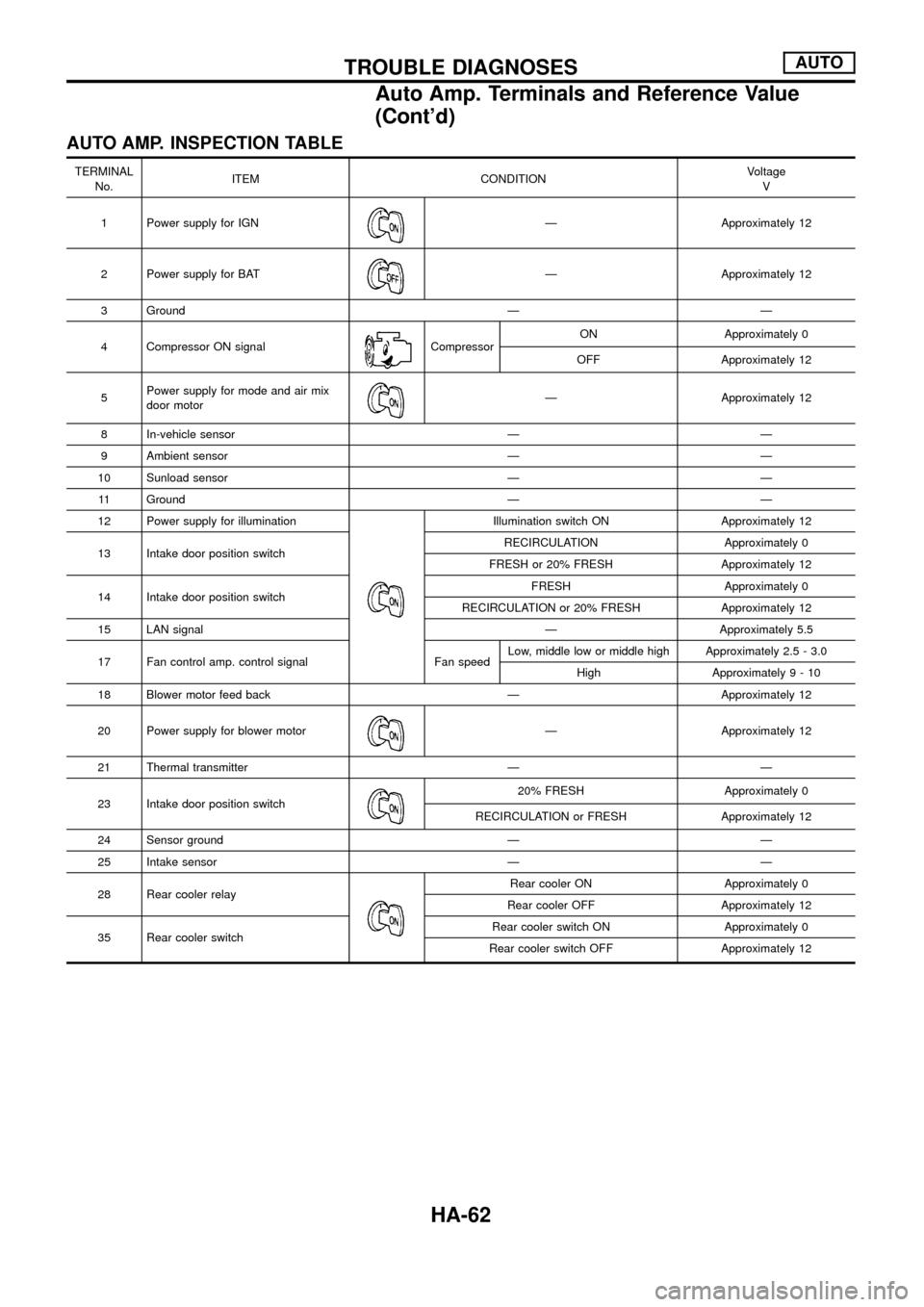
AUTO AMP. INSPECTION TABLE
TERMINAL
No.ITEM CONDITIONVoltage
V
1 Power supply for IGN
Ð Approximately 12
2 Power supply for BAT
Ð Approximately 12
3 Ground Ð Ð
4 Compressor ON signal
CompressorON Approximately 0
OFF Approximately 12
5Power supply for mode and air mix
door motor
Ð Approximately 12
8 In-vehicle sensor Ð Ð
9 Ambient sensor Ð Ð
10 Sunload sensor Ð Ð
11 Ground Ð Ð
12 Power supply for illumination
Illumination switch ON Approximately 12
13 Intake door position switchRECIRCULATION Approximately 0
FRESH or 20% FRESH Approximately 12
14 Intake door position switchFRESH Approximately 0
RECIRCULATION or 20% FRESH Approximately 12
15 LAN signal Ð Approximately 5.5
17 Fan control amp. control signal Fan speedLow, middle low or middle high Approximately 2.5 - 3.0
High Approximately9-10
18 Blower motor feed back Ð Approximately 12
20 Power supply for blower motor
Ð Approximately 12
21 Thermal transmitter Ð Ð
23 Intake door position switch
20% FRESH Approximately 0
RECIRCULATION or FRESH Approximately 12
24 Sensor ground Ð Ð
25 Intake sensor Ð Ð
28 Rear cooler relay
Rear cooler ON Approximately 0
Rear cooler OFF Approximately 12
35 Rear cooler switchRear cooler switch ON Approximately 0
Rear cooler switch OFF Approximately 12
TROUBLE DIAGNOSESAUTO
Auto Amp. Terminals and Reference Value
(Cont'd)
HA-62
Page 72 of 128
Operational Check
The purpose of the operational check is to con®rm that the system
operates properly.
CONDITIONS
+Engine running and at normal operating temperature.
PROCEDURE
1. Check memory function
a. Set the temperature 25ÉC.
b. Press OFF switch.
c. Turn the ignition off.
d. Turn the ignition on.
e. Press the AUTO switch.
f. Con®rm that the set temperature remains at previous tempera-
ture.
g. Press OFF switch.
2. Check blower
a. Press fan switch one time.
Blower should operate on low speed.
The fan symbol should have one blade lit
.
b. Press fan switch one more time, and continue checking blower
speed and fan symbol until all speeds are checked.
c. Leave blower on MAX speed
.
3. Check discharge air
a. Press mode switch four times and DEF button.
RHA517G
RHA518G
RHA519G
RHA520G
TROUBLE DIAGNOSESAUTO
HA-70
Page 75 of 128

A/C System
TROUBLE DIAGNOSIS PROCEDURE FOR A/C SYSTEM
SYMPTOM:
+A/C system does not come on.
Inspection ¯ow
*1: HA-74 *2: HA-70
COMPONENT DESCRIPTION
Automatic ampli®er (Auto amp.)
The auto ampli®er has a built-in microcomputer which processes
information sent from various sensors needed for air conditioner
operation. The air mix door motor, mode door motor, intake door
motor, blower motor and compressor are then controlled.
The auto ampli®er is unitized with control mechanisms. Signals
from various switches and Potentio Temperature Control (PTC) are
directly entered into auto ampli®er.
Self-diagnostic functions are also built into auto ampli®er to provide
quick check of malfunctions in the auto air conditioner system.
Potentio temperature control (PTC)
The PTC is built into the A/C auto amp. It can be set at an interval
of 1ÉC in the 18ÉC to 32ÉC temperature range by turning the tem-
perature dial. The set temperature is digitally displayed.
SHA019F
RHA629G
RHA746G
TROUBLE DIAGNOSESAUTO
HA-73
Page 87 of 128

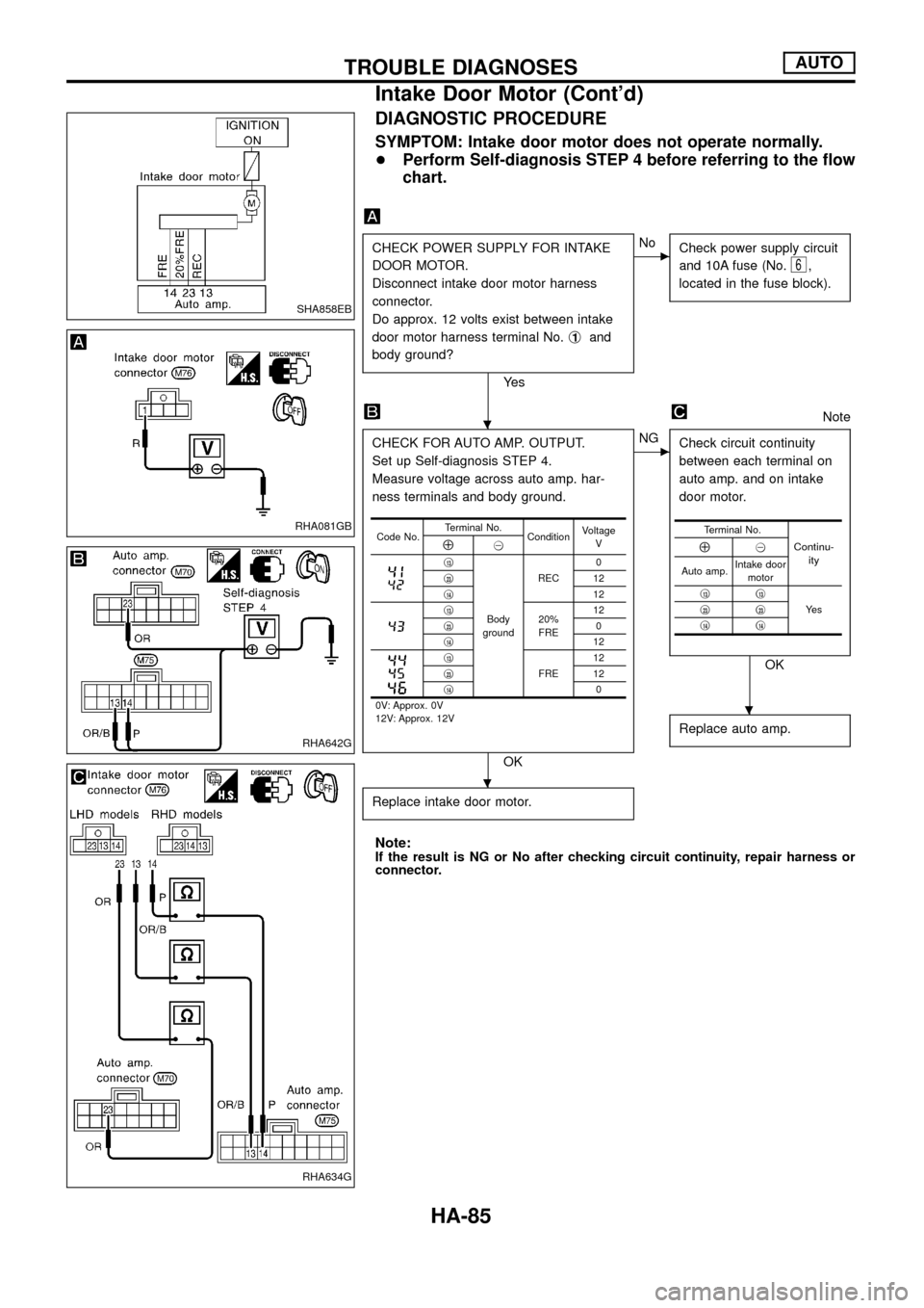
DIAGNOSTIC PROCEDURE
SYMPTOM: Intake door motor does not operate normally.
+Perform Self-diagnosis STEP 4 before referring to the ¯ow
chart.
CHECK POWER SUPPLY FOR INTAKE
DOOR MOTOR.
Disconnect intake door motor harness
connector.
Do approx. 12 volts exist between intake
door motor harness terminal No.j
1and
body ground?
Ye s
cNo
Check power supply circuit
and 10A fuse (No.
6,
located in the fuse block).
Note
CHECK FOR AUTO AMP. OUTPUT.
Set up Self-diagnosis STEP 4.
Measure voltage across auto amp. har-
ness terminals and body ground.
OK
cNG
Check circuit continuity
between each terminal on
auto amp. and on intake
door motor.
OK
Replace auto amp.
Replace intake door motor.
Note:If the result is NG or No after checking circuit continuity, repair harness or
connector.
Code No.Terminal No.
ConditionVoltage
VÅ@
j13
Body
groundREC0
j
2312
j
1412j1320%
FRE12
j230
j
1412j13
FRE12
j2312
j
140
0V: Approx. 0V
12V: Approx. 12V
Terminal No.
Continu-
ityÅ@
Auto amp.Intake door
motor
j
13j13
Ye s j23j23j14j14
SHA858EB
RHA081GB
RHA642G
RHA634G
.
.
.
TROUBLE DIAGNOSESAUTO
Intake Door Motor (Cont'd)
HA-85